
As a foundry engineer engaged in the production of complex, heavy-section components, I am consistently confronted with the challenge of manufacturing large-scale parts that meet stringent quality standards. Among these, large ductile iron castings present a unique set of considerations due to the material’s distinct solidification behavior. This article details a comprehensive approach to the process design and optimization for a substantial QT500-7 turbine volute housing, leveraging simulation to validate a novel, efficient sand casting strategy. The successful application of this methodology underscores the potential for advanced sand castings to achieve high integrity in demanding applications.
The component in question is a volute casing, a critical part in turbo machinery. Its primary function is to convert kinetic energy from the exhaust gas into pressure, requiring robust construction and pressure tightness. The challenges inherent in its production are immediately apparent from its geometry. The part is sizable, with overall envelope dimensions of 1512 mm x 1385 mm x 814 mm and a final weight approaching 2000 kg. Its internal geometry is a complex, scroll-like cavity, while externally it features several large flanges. A critical difficulty lies in the significant variation in wall thickness, ranging from a nominal 30 mm at the thinnest section of the inclined pipe to a hefty 100 mm at the large top plate. In ductile iron, such a large thermal gradient during solidification can lead to severe inhomogeneity in the graphite nodule distribution and matrix structure, potentially compromising the mechanical properties. Furthermore, the large mass and thick sections create a pronounced risk of shrinkage porosity. Traditional sand castings for such parts often rely on massive feeding risers, which drastically reduce yield and increase cleaning and machining costs. My objective was to design a sand casting process that ensured soundness, uniform microstructure, and high dimensional accuracy, while simultaneously improving material yield and simplifying molding operations.
The foundational step in any casting design is the selection of the pouring position and parting line. For this volute, two primary orientations were evaluated. The first positioned the large circular top plate at the bottom. This was quickly discounted, as it would place the critical, finely machined large-diameter bore surface at the top of the mold, making it susceptible to slag entrapment and gas defects. Furthermore, core support in this orientation would be problematic, requiring extensive use of chaplets which can lead to defects. The superior alternative, and the one I selected, positions the large top plate at the top of the mold. This crucial decision places the important bore surface downward, promoting its soundness, and allows the core to be securely anchored from above, eliminating the need for internal supports. The parting plane was logically chosen at the largest cross-section, which is a flat plane bisecting the volute’s height, simplifying pattern making and mold assembly.
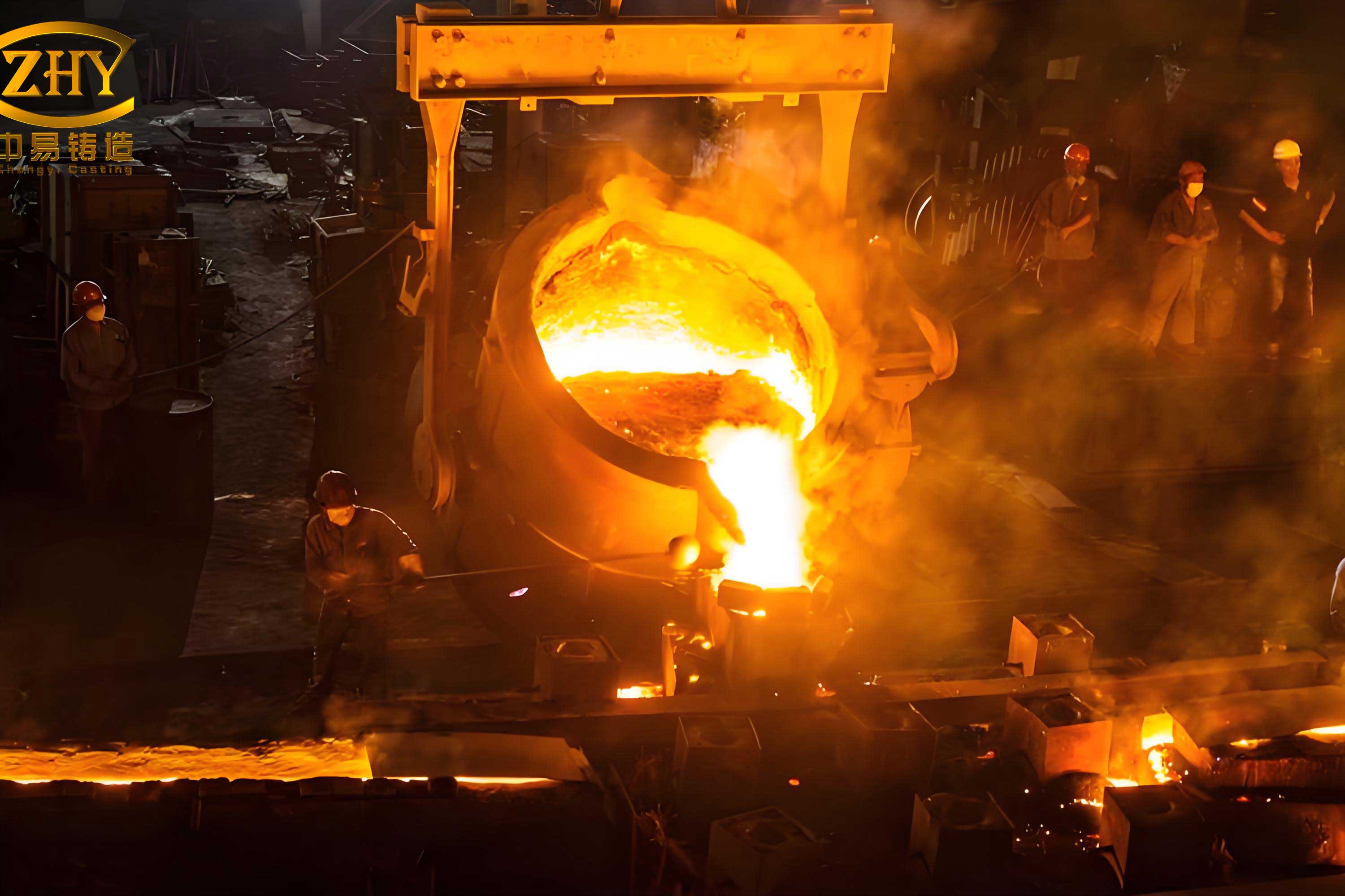
The heart of the innovation in this process lies in the gating system design and the strategic decision to pursue a riserless casting methodology. Conventional approaches for such volute sand castings often employ either peripheral gating around the scroll or bottom gating into the thick lower sections. Analysis revealed drawbacks: peripheral gating leads to long flow paths, increased risk of mold erosion (washing), and turbulent filling; bottom gating into thick sections can exacerbate thermal gradients and often necessitates complex three-part molds. I proposed a targeted gating strategy. The internal ingates were positioned symmetrically on the outer edges of the flange adjacent to the thinnest section (the inclined pipe). This location leverages the natural flow path provided by the scroll’s geometry. Metal enters here, flows into the curved base of the flange, and then smoothly fills the spiral cavity in a controlled, bottom-up manner. This design offers the shortest possible gating length, minimizing heat loss and oxidation, and promotes a uniform temperature gradient by introducing hot metal near the thinnest, fastest-cooling section. The goal is to minimize the solidification temperature difference (ΔT) across the casting, promoting more uniform graphite formation. The thermal gradient can be conceptualized by the Fourier heat conduction law, though in a complex 3D casting it is solved numerically:
$$ \nabla \cdot (k \nabla T) = \rho C_p \frac{\partial T}{\partial t} $$
where \( k \) is thermal conductivity, \( \rho \) is density, \( C_p \) is specific heat, and \( T \) is temperature.
The most significant departure from standard practice was the elimination of feed risers. For a typical gray iron or steel casting of this size and section thickness, substantial risers would be mandatory to feed solidification shrinkage. However, ductile iron undergoes a pronounced expansion during the eutectic solidification phase due to graphite precipitation, which has a lower density than the liquid austenite. This expansion can be harnessed to counteract the initial liquid contraction and the subsequent solid-state shrinkage, enabling riserless casting if certain conditions are met. The key is to create a “rigid mold wall” scenario where the expansion pressure is contained and directed inward to feed the remaining liquid. The net volume change during solidification (ΔV_net) can be expressed as:
$$ \Delta V_{net} = \Delta V_{shrinkage} + \Delta V_{graphite-expansion} $$
For successful riserless casting, the process must be designed so that \( \Delta V_{net} \geq 0 \), or practically, that the expansion compensates for the shrinkage. To achieve this, several conditions were implemented:
- High Mold Rigidity: The mold was constructed using furan resin-bonded sand for high strength and baked to enhance its rigidity. A stout flask system was employed to further resist mold wall movement.
- Early Gates Freeze-Off: The ingates were designed with a relatively small cross-section to ensure they solidify and seal before the main casting body. This isolates the casting from the liquid in the pouring basin and sprue, preventing pressure relief back through the gating system. The freezing time can be approximated using the Chvorinov’s rule, where the modulus (Volume/Surface Area) of the gate is made smaller than that of the critical casting sections it feeds.
- Controlled Pouring Temperature: A relatively low pouring temperature (1280-1290°C) was specified. This promotes rapid formation of a strong, solid skin (an “early shell”) around the casting, which is essential for containing the internal expansion pressure.
- Aided Cooling: Strategic use of insulating sleeves and chill materials was planned. External chills were placed on the thick top plate to promote directional solidification toward the thinner walls and the now-sealed ingates, while insulating material was used in the core to slow cooling in the complex internal cavity, reducing thermal stress.
The table below summarizes the key process parameters designed to enable the riserless sand casting of this large ductile iron volute:
| Process Parameter | Design Choice | Rationale & Function |
|---|---|---|
| Molding Method | Furan Resin No-Bake Sand, Flasked | Provides high strength and dimensional accuracy for large sand castings; flask resists expansion pressure. |
| Pouring Position | Large Top Plate Upwards | Puts critical bore surfaces down for quality; simplifies core support. |
| Gating Location | At thin-section flange | Minimizes thermal gradient ΔT, promotes uniform filling and microstructure. |
| Feeding Method | Riserless (Self-feeding via expansion) | Exploits graphite expansion; increases yield, reduces cleaning cost. |
| Pouring Temperature | 1280 – 1290 °C | Promotes rapid skin formation to contain expansion pressure. |
| Gating Design | Fast-filling, small modulus ingates | Ensures early freeze-off to seal casting system. |
| Auxiliary Tools | Top chills, insulating core coats | Controls solidification sequence, minimizes shrinkage risk. |
To validate this comprehensive design before committing to costly tooling and trial pours, numerical simulation was indispensable. I utilized a commercial casting simulation software (AnyCasting was referenced in the source material) to analyze the filling, solidification, and defect formation. A 3D model of the part, cores, gating, and chills was created and meshed. The key material properties for QT500-7 were input, and the process parameters were set according to the design.
The filling analysis confirmed the efficacy of the gating design. The simulation showed a smooth, progressive fill sequence. Metal entered symmetrically through the two ingates, quickly filled the annular base of the flange, and then advanced upward through the spiral cavity in a controlled, layered fashion. The total fill time was approximately 36 seconds. Crucially, no significant turbulence, air entrainment, or cold shuts were predicted. This laminar fill is highly beneficial for the quality of sand castings, as it minimizes oxide formation and mold erosion.
The solidification simulation was the critical test for the riserless concept. The results visually demonstrated the intended sequence. The thin walls and the strategically designed ingates solidified first, creating an isolated, sealed cavity. The use of chills on the thick top plate effectively promoted cooling from that top surface inward. The most important observation was the absence of isolated liquid hot spots deep within the thick sections at the end of solidification. The temperature gradient was managed effectively. The software’s shrinkage prediction module indicated a very low risk of macro-shrinkage porosity. The only regions flagged for potential micro-porosity were confined to the top of the large plate within the designated machining allowance and the inevitable junction hot spots in the gating system itself, which is inconsequential. This confirmed that the combination of controlled cooling and the utilization of graphite expansion was functioning as designed to produce sound sand castings.
The table below contrasts the key outcomes of the proposed optimized design against a conventional risered approach for such a large ductile iron sand casting:
| Aspect | Conventional Riserred Approach | Proposed Optimized Riserless Approach |
|---|---|---|
| Yield (Cast Weight / Poured Weight) | Low (~50-60%). Large risers required to feed thick sections. | High (>75%). No risers; only gating system as yield loss. |
| Filling Pattern | Potentially turbulent with long flow paths in peripheral/bottom gating. | Smooth, progressive bottom-up fill leveraging scroll geometry. |
| Thermal Gradient (ΔT) | Can be high if gating feeds thick areas, promoting microstructural variation. | Minimized by gating into thin section, promoting uniform graphite formation. |
| Post-Casting Operations | Extensive riser removal, grinding, and cleanup. | Significantly reduced cleanup; only gating removal required. |
| Mold Complexity | May require more complex cores or mold parts to accommodate risers. | Simpler mold architecture; core support is straightforward. |
| Defect Risk (Shrinkage) | Risk transferred to riser; if undersized, shrinkage moves into casting. | Risk mitigated by controlled solidification and harnessed expansion. |
In conclusion, the sand casting of large, complex ductile iron components like turbine volutes demands a holistic design philosophy that integrates material science, process engineering, and advanced simulation. By meticulously analyzing the component’s geometry and the unique solidification characteristics of ductile iron, I developed a process that challenges conventional wisdom. Positioning the pour to maximize critical surface quality and core stability, coupled with a gating system designed to balance thermal gradients, addresses the challenge of microstructural uniformity. The bold step of implementing a riserless casting strategy, backed by the rigorous conditions of high mold rigidity, early gate freeze-off, and controlled cooling, successfully harnesses the inherent graphite expansion of the material. This approach transforms a potential problem—expansion—into the primary solution for feeding. The pre-production numerical simulation provided robust validation, demonstrating smooth filling, controlled solidification, and a high probability of sound castings. This methodology results in an optimal match of casting quality, material efficiency, and reduced manufacturing cost for heavy-section ductile iron sand castings, proving that innovative process design can yield significant technical and economic advantages in modern foundry practice.