
With the advancement of steel production and processing technologies, the manufacturing technology for spheroidal graphite cast iron has seen significant improvement. Coupled with its excellent cost-performance ratio, its application scope has broadened considerably in recent years, becoming a substitute for cast steel and gray iron castings in numerous industries. However, spheroidal graphite cast iron is not without its flaws, particularly in heavy-section castings where quality issues frequently arise. In response to these problems, domestic and international researchers have begun to investigate, analyzing their causes and influencing factors. Based on an analysis of common defects in spheroidal graphite cast iron, this article conducts experimental studies on heavy-section marine castings produced by a company, discussing the factors influencing defects in large spheroidal graphite cast iron components. The aim is to provide insights and methods for improving the production technology of large marine spheroidal graphite cast iron castings.
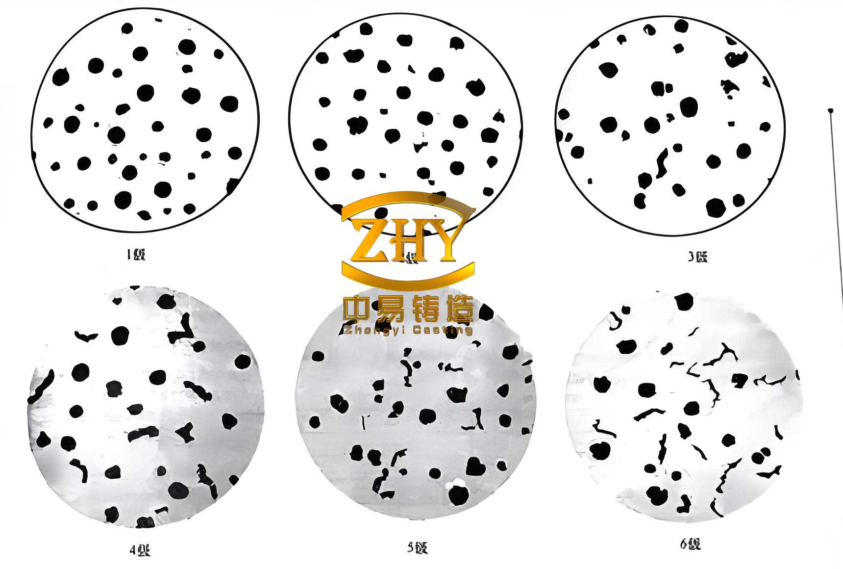
The superior properties of spheroidal graphite cast iron stem from its unique microstructure, where the graphite is present in a spherical form rather than the flakes found in gray iron. This spheroidal morphology is achieved through the inoculation of the molten iron with elements like magnesium and cerium, which alter the solidification kinetics. The resulting material offers a compelling combination of strength, ductility, and castability, making it ideal for demanding marine applications such as propeller hubs, stern frames, and large valve bodies. However, the very processes that confer these benefits also make the production of heavy-section castings susceptible to specific defects. The extended solidification time of thick sections alters the thermal and metallurgical conditions, often exacerbating issues that are minor or absent in thinner walled castings. Understanding and controlling these factors is therefore paramount for ensuring the reliability of critical marine components made from spheroidal graphite cast iron.
1. Analysis of Typical Defects
The production of large spheroidal graphite cast iron castings is a complex process where deviations in chemistry, process control, or melt treatment can lead to a range of defects that compromise mechanical integrity. The following sections detail the most prevalent issues encountered.
1.1 Nodularization Deficiency (Poor Spheroidization)
Nodularization deficiency leads to a significant degradation in the mechanical properties of the casting, markedly reducing its elongation. The characteristic feature of this defect is a fracture surface exhibiting a silver-gray color with unevenly distributed black spots. Observation under an optical microscope reveals that graphite exists primarily in a flake form within graphite aggregation zones. The few spheroidal graphite particles present are typically large (classified as size 5), and the overall nodularity rating is very low, often between grades 2 and 3.
Based on thermal analysis theory, the primary cause of poor spheroidization in castings is the influence of the residual content of elements like magnesium (Mg) and rare earths (RE, often Cerium – Ce) in the molten iron. Insufficient levels of these nodularizing agents fail to effectively suppress the formation of flake graphite. The reasons for suboptimal Mg/RE levels are multifaceted. Impurities in the charge materials and inadequate slag removal (de-slaging) during melting can lead to elevated sulfur (S) and active oxygen content in the iron melt. These elements readily react with and consume the potent nodularizing elements, reducing their effectiveness. Furthermore, during the pouring process, magnesium, being highly volatile, can be further depleted, especially if there is a long transfer time or excessive turbulence, leading to fading of the nodularizing effect and consequent poor spheroidization by the time the metal solidifies. The reaction can be conceptually represented as:
$$ \text{Mg} + \text{S} \rightarrow \text{MgS} \quad \text{(Slag)} $$
$$ \text{RE} + \text{O} \rightarrow \text{RE-oxides} \quad \text{(Slag)} $$
These reactions effectively remove the crucial nodularizing elements from the melt.
1.2 Shrinkage Porosity
Shrinkage porosity defects primarily manifest as fly-foot-like black dots or dark, loose pores, usually occurring in hot spots and often forming just beneath the casting surface. Micro-shrinkage forms during the final stages of secondary solidification, primarily due to the solidification of interdendritic or inter-eutectic cell liquid iron under negative pressure conditions. Shrinkage porosity is a characteristic and often challenging defect unique to spheroidal graphite cast iron castings, distinguishing them from other cast materials. During solidification, the unique expansion associated with graphite precipitation can, under certain conditions, create internal voids if the feeding is inadequate. This happens when the expansion pressure is insufficient to compensate for the contraction in areas that solidify last, leading to a vacuum or negative pressure zone that results in porosity upon complete solidification.
The root causes are often linked to the melt chemistry and treatment. Inadequate slag removal leads to severe oxidation of the iron, destabilizing its chemical composition. Key elements significantly impacting shrinkage include carbon equivalent (CE), sulfur (S), and phosphorus (P). A decrease in carbon equivalent reduces the amount of graphite precipitated, thereby diminishing the beneficial expansion that can counteract shrinkage, leading to increased porosity. Conversely, elevated levels of sulfur and phosphorus increase the consumption of magnesium and rare earths, hindering effective nodularization and reducing the fluidity and feeding capability of the remaining liquid, thus promoting shrinkage. The relationship between graphite expansion and shrinkage compensation is critical. The expansion volume $V_{exp}$ from graphite precipitation can be approximated as a function of the carbon content:
$$ V_{exp} \propto C_{graphite} $$
where $C_{graphite}$ is the mass of graphite formed. If the mold rigidity is insufficient to contain this expansion to aid feeding, or if the expansion occurs too early/late relative to the solidification sequence, shrinkage defects will form.
1.3 Gas Porosity (Blowholes/Pinholes)
Gas pores in castings typically form 2-3 mm beneath the surface. They can vary in shape, appearing as spherical or elongated oval cavities, sometimes distributed in a honeycomb pattern, or as smooth-walled pinholes. This defect is more common in smaller spheroidal graphite cast iron castings but can also plague heavy sections if gases are trapped. The primary cause is linked to the mushy solidification mode of spheroidal graphite cast iron. As solidification progresses, the surface tension of the liquid increases, and a solid oxide film can form on the advancing solid-liquid interface. This film can trap gases (such as hydrogen, nitrogen, or carbon monoxide) nucleated within the melt, preventing their escape. Upon complete solidification, these trapped gases remain as pores just below the surface.
Additionally, in certain casting processes like lost foam casting, gases generated from the decomposition of the EPS (Expanded Polystyrene) pattern must be efficiently evacuated. If the venting of the mold is insufficient, these gases can be forced into the solidifying metal, causing gas porosity. While more common in thin-section castings due to faster solidification rates trapping gases, in large spheroidal graphite cast iron castings, slow solidification can allow gases to coalesce into larger bubbles if not properly vented or if the melt gas content is high. The solubility of gas in liquid iron, such as hydrogen, decreases sharply upon solidification, described by Sieverts’ law:
$$ S_H = k_H \sqrt{P_{H_2}} $$
where $S_H$ is the solubility of hydrogen, $k_H$ is the equilibrium constant, and $P_{H_2}$ is the partial pressure of hydrogen. The drastic drop in solubility upon cooling forces the excess gas out of solution, potentially forming pores if nucleation sites are present and the solidification front is impermeable.
1.4 Cracking (Hot Tears and Cold Cracks)
Cracks occur when the internal stresses developed during solidification and cooling exceed the metal’s fracture strength at that temperature, representing a form of self-inflicted failure. When fracture occurs at a high temperature (above approximately 1000°C), the fracture surface appears dark brown or oxidized; this is termed hot tearing. When fracture occurs at lower temperatures (typically below 600°C), the fracture surface is brighter and less oxidized, known as cold cracking.
Analysis shows that insufficient nodularization increases the chilling tendency (formation of carbides), which reduces ductility and promotes cold cracking. Rapid cooling rates, often due to inadequate mold design or the use of excessive chills in heavy sections, can generate high thermal stresses. If these stresses combine with existing microstructure stresses (e.g., from sharp section changes), cracks can initiate at stress concentrators like edges, corners, or internal re-entrant angles. Phosphorus is a particularly detrimental element regarding cracking. When its content exceeds about 0.025-0.030% in heavy-section spheroidal graphite cast iron, it forms a low-melting-point phosphide eutectic network along grain boundaries. This brittle network severely weakens the grain boundaries at high temperatures, making the casting highly susceptible to hot tearing during the final stages of solidification when tensile stresses are developing. The susceptibility to hot tearing $S_{ht}$ can be qualitatively expressed as a function of several factors:
$$ S_{ht} \propto \frac{\sigma_t \cdot \delta}{E \cdot \epsilon_f} $$
where $\sigma_t$ is the thermal stress, $\delta$ is the solid fraction range of vulnerability, $E$ is the elastic modulus, and $\epsilon_f$ is the fracture strain of the semi-solid material. High phosphorus content drastically reduces $\epsilon_f$.
2. Experimental Methodology and Results
To systematically investigate the factors influencing defects in large marine spheroidal graphite cast iron castings, a controlled experimental study was designed and executed. The study focused on simulating the conditions of heavy-section castings and isolating key variables.
2.1 Experimental Design and Procedure
Considering the application requirements for marine-grade spheroidal graphite cast iron, castings with a range of wall thicknesses were selected for study. The experimental setup involved producing stepped plate castings, where a single casting incorporated sections of progressively increasing thickness. This design allows for the observation of defect formation across a spectrum of cooling rates within one pour, ensuring consistent base iron chemistry. The wall thicknesses chosen were 40 mm, 80 mm, 120 mm, 180 mm, and 220 mm. All sections except the thickest (220 mm) had a length of 250 mm to provide sufficient area for evaluation.
The charge materials consisted of 35% high-quality steel scrap and 65% high-purity pig iron, with supplemental carburizer added to achieve target carbon levels. Melting was conducted in a 1.5-ton medium-frequency induction furnace, with a maximum superheat temperature of 1500°C to ensure complete dissolution of charge materials and effective carburization. The melt treatment involved a two-step process: nodularization and inoculation, both performed using the sandwich method in a preheated treatment ladle. The nodularizing agent was a REMgFeSi alloy, and the inoculant was a SiBaFe alloy. Each treatment batch processed approximately 1 ton of molten iron. To study the effect of pouring temperature, four distinct pouring temperatures were established for different melts: 1310°C, 1330°C, 1350°C, and 1370°C. Thermal analysis was performed using a calibrated thermal analysis cup to record cooling curves, which provide critical information on nucleation undercooling, recalescence, and eutectic solidification characteristics. After shakeout and cleaning, all castings were subjected to visual inspection, followed by non-destructive and destructive testing at specific locations corresponding to each wall thickness.
2.2 Chemical Composition Control
Four distinct melting and treatment schemes were devised to create iron with varying carbon equivalents (CE), which is a key parameter defined as CE = %C + ⅓ %Si. The target was to produce melts with low, medium-low, medium-high, and high carbon equivalents while controlling other elements. The chemical compositions of the treated iron for the four schemes, as determined by optical emission spectrometry, are presented in Table 1. Sulfur and phosphorus were kept as low as possible, and manganese was maintained at a consistent moderate level to avoid promoting pearlite formation excessively.
| Scheme ID | Chemical Composition wB / % | CE (%) | ||||
|---|---|---|---|---|---|---|
| C | Si | S | P | Mn | ||
| Scheme 1 | 3.55 | 1.38 | 0.010 | 0.015 | 0.22 | 4.01 |
| Scheme 2 | 3.65 | 1.68 | 0.010 | 0.015 | 0.22 | 4.21 |
| Scheme 3 | 3.75 | 2.01 | 0.012 | 0.015 | 0.23 | 4.42 |
| Scheme 4 | 3.85 | 2.28 | 0.012 | 0.015 | 0.22 | 4.61 |
2.3 Summary of Defect Observations
A comprehensive evaluation of the castings produced under the four schemes revealed distinct patterns linking defect occurrence to chemical composition and casting parameters. The key defects monitored were shrinkage porosity, graphite flotation, and the formation of degenerate graphite forms like chunky graphite. The primary influencing factors identified from this analysis were Carbon Equivalent (CE), graphite morphology control, and the role of trace elements.
3. Discussion of Results and Influencing Factors
3.1 The Dual Role of Carbon Equivalent on Shrinkage and Graphite Flotation
The carbon equivalent is arguably the most critical parameter controlling the solidification behavior and soundness of spheroidal graphite cast iron. Its effect on shrinkage porosity is paradoxical. Shrinkage in spheroidal graphite cast iron occurs due to an imbalance between the contraction of the austenite dendrites and the expansion from graphite precipitation. When the carbon equivalent is stable, increasing wall thickness prolongs the solidification time. If the feeding from risers or adjacent sections is inadequate during this extended period, shrinkage porosity will likely form in the thermal centers. Conversely, for a constant wall thickness, a higher carbon equivalent generally improves inoculation effectiveness and increases the volume of graphite precipitated. The associated expansion force $F_{exp}$ can be conceptually related to the graphite volume fraction $f_g$:
$$ F_{exp} \propto f_g \approx k \cdot (\text{CE} – \text{CE}_{min}) $$
where $k$ is a constant and $\text{CE}_{min}$ is a threshold value. If the mold wall strength and rigidity are sufficient to withstand this expansion force and use it to compress and feed remaining liquid pools, shrinkage can be eliminated. Therefore, judiciously increasing the carbon equivalent can promote “self-feeding” via graphite expansion.
However, excessively increasing the carbon equivalent introduces the severe defect of graphite flotation. This occurs when graphite nodules, having a lower density than the liquid iron, float to the upper surfaces of the casting during the long liquid stage of heavy sections. The tendency for flotation increases dramatically with higher CE and higher pouring temperature. The settling (or floating) velocity $v$ of a graphite nodule can be approximated by Stokes’ law:
$$ v = \frac{2 g r^2 ( \rho_{Fe} – \rho_{gr})}{9 \eta} $$
where $g$ is gravity, $r$ is the nodule radius, $\rho_{Fe}$ and $\rho_{gr}$ are the densities of iron and graphite, and $\eta$ is the viscosity of the molten iron. Larger nodules (from high CE) and lower viscosity (from high temperature) increase $v$, promoting flotation. In the experimental conditions, a clear trade-off was observed. For a pouring temperature of 1370°C, in sections with wall thickness up to 120 mm, the carbon equivalent needed to be controlled within the range of 4.01% to 4.42% to avoid significant shrinkage while minimizing graphite flotation. Exceeding the upper limit consistently led to a layer of degenerated graphite and slag inclusions on the cope surfaces of thicker sections.
3.2 Carbon Equivalent and the Formation of Chunky Graphite
Beyond flotation, another critical degeneration phenomenon in heavy-section spheroidal graphite cast iron is the formation of chunky graphite. This appears as compact, irregularly shaped graphite aggregates in the thermal centers of very thick sections, severely reducing mechanical properties, especially ductility and impact toughness. Observations from the experimental castings confirmed a strong correlation. When the carbon equivalent exceeded approximately 4.42% and the wall thickness was greater than 120 mm, the central regions of the thick sections began to exhibit chunky graphite. The severity and extent of the chunky graphite zone increased with both increasing CE and increasing wall thickness (i.e., decreasing cooling rate). This is because slow cooling in a high-carbon environment allows for excessive diffusion of carbon and long-distance interaction between growing graphite nodules, leading to their interconnection and degeneration. The growth morphology transitions from spheroidal to an irregular, compact aggregate form. The critical cooling rate $ \dot{T}_{crit} $ to avoid chunky graphite decreases with increasing CE, forming a process window that must be navigated for producing sound heavy-section spheroidal graphite cast iron components.
3.3 The Impact of Trace Elements on Graphite Morphology
Certain trace elements, when added in minute quantities, can powerfully influence graphite morphology, particularly in suppressing degenerate forms like chunky graphite. To investigate this, a follow-up experiment was conducted based on the previous schemes. Small, controlled additions of Antimony (Sb) and Bismuth (Bi) were made to separate melts with compositions similar to Schemes 2 and 4. Furthermore, for some pours, external chills (flat iron plates) of different sizes were placed against the mold walls to locally increase the cooling rate.
The results were striking. With the addition of a small amount of Sb (on the order of 0.002-0.004%), none of the four scheme-based castings showed evidence of chunky graphite in their thermal centers, even at high CE and large wall thickness. The mechanism is believed to be that Sb segregates strongly at the growing graphite/liquid interface. This segregation layer acts as a diffusion barrier, impeding the rapid diffusion of carbon atoms to the graphite nodule. This suppression of carbon diffusion rate helps maintain a steeper concentration gradient around the nodule, stabilizing its spherical growth mode and preventing the cooperative, degenerate growth that leads to chunky graphite. The effect can be modeled as Sb increasing the interfacial energy $\gamma_{gr/liq}$ or creating a kinetic barrier, modifying the graphite growth rate $G$:
$$ G \propto D_C \cdot \nabla C \cdot f(\gamma) $$
where $D_C$ is the carbon diffusion coefficient and $\nabla C$ is the carbon concentration gradient. Sb reduces the effective $D_C$ at the interface.
Comparing castings with and without trace additions and chills revealed that combining a small Sb addition with strategically placed chills produced the most refined and spherical graphite structure. The nodule count increased significantly, and the graphite size was refined to a grade 6 or better according to ASTM A247. However, a critical limitation was identified: the Sb addition must be precisely controlled. If the Sb content exceeds approximately 0.007%, it acts as a potent pearlite stabilizer. This leads to the formation of a fully pearlitic matrix, which, while increasing strength and hardness, eliminates the desired ferritic matrix and drastically reduces the ductility and impact toughness required for many marine applications of spheroidal graphite cast iron. Thus, the beneficial effect on graphite shape has a very narrow compositional window. The effect of key parameters is summarized in Table 2 below.
| Parameter | Primary Effect | Optimal Range (Example) | Consequence of Excess | Consequence of Deficiency |
|---|---|---|---|---|
| Carbon Equivalent (CE) | Controls graphite volume, feeding expansion, and fluidity. | 4.2% – 4.5% (for ~150mm section, 1350°C pour) | Graphite flotation, Chunky Graphite. | Increased shrinkage porosity, poor inoculation. |
| Residual Mg | Ensures spheroidal graphite formation. | 0.03% – 0.06% | Carbide formation, dross defects. | Poor nodularity (flake/vermicular graphite). |
| Pouring Temperature | Affects fluidity, gas solubility, and cooling rate. | 1320°C – 1360°C | Increased gas pickup, mold erosion, severe graphite flotation. | Misruns, cold shuts, poor mold filling. |
| Trace Sb Addition | Suppresses chunky graphite formation. | < 0.007% (e.g., 0.002-0.005%) | Promotes pearlite, reduces ductility. | No suppression of chunky graphite in heavy sections. |
| Phosphorus (P) | — (Impurity to be minimized) | < 0.025% | Promotes hot tearing, reduces toughness. | — |
| Sulfur (S) | — (Impurity to be minimized) | < 0.015% pre-treatment | Consumes Mg/RE, causes nodularization failure. | — |
4. Conclusions and Recommendations for Practice
Through the analysis of typical defects and systematic experimental investigation, this study clarifies the complex interdependencies of factors affecting the quality of large, heavy-section marine spheroidal graphite cast iron castings. The production of sound components requires navigating a narrow process window defined by chemistry, thermal conditions, and melt treatment.
The primary conclusions are as follows:
- Carbon Equivalent is a Pivotal but Double-Edged Sword: Both excessively high and low carbon equivalent values detrimentally affect the integrity of spheroidal graphite cast iron castings. Low CE promotes shrinkage porosity by reducing beneficial graphite expansion. High CE, while aiding feeding, inevitably leads to graphite flotation and the formation of chunky graphite in the slow-cooling centers of heavy sections. Therefore, in practice, the carbon equivalent must be meticulously controlled based on the specific wall thickness of the marine spheroidal graphite cast iron component and the chosen pouring temperature. A lower CE is tolerable for thinner sections or lower pouring temperatures, while thicker sections require a higher CE for feeding but must contend with degeneration risks.
- Identifying a Practical CE Window: Based on the experimental conditions involving section thicknesses up to 220 mm and pouring temperatures from 1310°C to 1370°C, maintaining the carbon equivalent within the range of 4.2% to 4.5% generally provides the best compromise. This range maximizes the graphite expansion for self-feeding to counteract shrinkage while keeping the risks of severe graphite flotation and chunky graphite formation at manageable levels for most heavy-section geometries.
- Strategic Use of Trace Elements and Cooling Control: The deliberate addition of trace amounts of elements like Antimony (Sb) is highly effective in suppressing the formation of chunky graphite, a major concern in heavy-section spheroidal graphite cast iron. However, dosage control is critical; the addition must not exceed approximately 0.007% to avoid the undesirable side effect of stabilizing a pearlitic matrix. Furthermore, this microalloying approach can be effectively combined with engineered cooling using strategically sized and placed chills. Chills can locally increase the solidification rate, shifting the local thermal conditions away from the regime conducive to degenerate graphite formation. This combination provides a robust method for ensuring spherical graphite morphology throughout the entire cross-section of a large spheroidal graphite cast iron casting.
Successfully manufacturing large, defect-free marine components from spheroidal graphite cast iron therefore hinges on an integrated approach. It requires precise charge calculation and melt chemistry control, rigorous slag management and melt treatment procedures, optimized gating and risering design to promote directional solidification, and the judicious application of microalloying and cooling modifiers to control graphite morphology in slow-cooling zones. By understanding and applying the principles derived from the analysis of these influencing factors, manufacturers can significantly improve the consistency, reliability, and performance of these critical castings.