
In our manufacturing operations, we encountered a critical machining defect in a wheel hub made from QT500-7 spheroidal graphite cast iron. The hub, intended for heavy-duty equipment, had an installation hole with a specified diameter of 320 mm and depth of 20 mm that was machined oversize, rendering it unfit for assembly. Given the high cost and lead time associated with recasting the component, we opted to explore welding repair as a solution. This article details our comprehensive approach, from analyzing the structure of the wheel hub and the weldability of spheroidal graphite cast iron to implementing a tailored welding procedure that successfully restored the component to meet all performance requirements.
The wheel hub in question is a critical load-bearing component, and its integrity is paramount. The defect was localized to the installation hole, which is relatively shallow, making it amenable to weld repair. However, the challenge lay in ensuring that the welding process did not induce distortions or alter the dimensions of other machined features, as the hub needed to be re-clamped and re-machined based on original datums. We began by thoroughly examining the hub’s geometry and material properties.
The base material, QT500-7 spheroidal graphite cast iron, is characterized by its graphite nodules embedded in a ferritic-pearlitic matrix, providing a combination of strength and ductility. Its nominal mechanical properties are summarized in Table 1.
| Property | Value | Notes |
|---|---|---|
| Tensile Strength | ≥ 500 MPa | Minimum requirement |
| Yield Strength | ≥ 320 MPa | Minimum requirement |
| Elongation | ≥ 7 % | Minimum requirement |
| Hardness | 170–230 HBW | Typical range |
| Primary Matrix | Ferrite + Pearlite | Microstructure |
Understanding the weldability of spheroidal graphite cast iron is crucial for a successful repair. The high carbon content (typically 3.2–4.1 wt%) in spheroidal graphite cast iron poses significant challenges during welding. The primary issues are the formation of white iron (cementite) and hard brittle phases like martensite in the heat-affected zone (HAZ) and fusion zone, as well as the propensity for cold and hot cracking.
The rapid cooling inherent in welding processes can suppress the stable transformation of austenite to ferrite and graphite, leading to the precipitation of metastable cementite (Fe3C). This phenomenon, known as white iron formation, results in extreme hardness and brittleness. The cooling rate, $ \dot{T} $, is a key factor and can be approximated for a thin-section weld as:
$$ \dot{T} = \frac{2 \pi k (T – T_0)^2}{Q} $$
where $ k $ is the thermal conductivity, $ T $ is the temperature, $ T_0 $ is the ambient temperature, and $ Q $ is the heat input per unit length. For spheroidal graphite cast iron, a high $ \dot{T} $ promotes carbide formation. Furthermore, carbon migration from the base metal into the weld pool can elevate the carbon equivalent (CE) of the fusion zone. The carbon equivalent for cast iron is often expressed as:
$$ \text{CE} = \%\text{C} + \frac{\%\text{Si} + \%\text{P}}{3} $$
A high CE increases the hardenability, leading to martensitic transformation upon fast cooling. The hardness of martensite, $ H_v $, can be related to carbon content $ C $ (in wt%) by empirical relations such as:
$$ H_v \approx 1667C – 926C^2 + 150 $$
This underscores the risk of creating a hard, crack-sensitive region. Cracking mechanisms are twofold. Cold cracks, or hydrogen-induced cracks, can occur in the HAZ or weld metal when susceptible microstructures like martensite are present under tensile stress. The stress intensity is influenced by thermal contraction. Hot cracks, or solidification cracks, arise from low-melting eutectics (e.g., iron-sulfide or nickel-sulfide phases) segregating at grain boundaries during the final stages of solidification. The susceptibility increases with impurities like sulfur and phosphorus.
To mitigate these issues, the selection of appropriate filler metal and stringent control of welding parameters are essential. For repair of spheroidal graphite cast iron components requiring machinability and strength matching the base metal, nickel-based electrodes are often preferred. We selected a nickel-iron electrode conforming to AWS ENiFe-CI (commonly designated as Z408). Its mechanical properties are listed in Table 2.
| Property | Value | Notes |
|---|---|---|
| Tensile Strength | ≥ 490 MPa | As deposited |
| Yield Strength | ≥ 385 MPa | As deposited |
| Elongation | ≥ 14 % | As deposited |
The nickel content (approx. 55% Ni, 45% Fe) promotes a ductile austenitic matrix that can absorb carbon without forming brittle carbides, thereby reducing the hardness gradient. The yield strength is comparable to QT500-7 spheroidal graphite cast iron, while the higher elongation provides superior crack resistance through stress relaxation. This constitutes an overmatching in ductility and under matching in strength, which is beneficial for weld repair of spheroidal graphite cast iron.
Our welding methodology employed shielded metal arc welding (SMAW), or stick welding, due to its flexibility and low heat input capability. The core principle was “cold welding” with strict thermal management to minimize the heat-affected zone and residual stresses. The procedure was as follows:
- Preparation: The weld area and surrounding 200 mm were meticulously cleaned of oil, moisture, and contaminants using lint-free cloths and then heated with an oxy-acetylene torch to approximately 150–200°C to drive off any absorbed hydrogen and volatiles. The component was allowed to cool to below 60°C before welding commenced.
- Welding Parameters: We used 3.2 mm diameter Z408 electrodes with a direct current electrode positive (DCEP) polarity. The current was set between 80–120 A, optimized through test runs to achieve stable arc and minimal dilution. The heat input, $ H $, for each short segment was kept low:
$$ H = \frac{60 \cdot V \cdot I}{1000 \cdot S} $$
where $ H $ is in kJ/mm, $ V $ is arc voltage (approx. 22–24 V), $ I $ is current in amperes, and $ S $ is travel speed in mm/min. For our parameters, $ H $ was maintained below 0.8 kJ/mm.
- Welding Technique – Staggered Segmenting and Peening: The circumferential weld was divided into 30 segments, each not exceeding 40 mm in length. Welding was performed in a staggered, skip-sequence pattern to distribute heat. The hub was positioned with the weld axis vertical. We initiated welding on three consecutive segments, then rotated the hub 180° to weld the opposite side, followed by 90° rotations to address intermediate sections. This pattern ensured symmetrical heat distribution. Crucially, after depositing each short segment, we immediately peened the weld bead using a round-nose hammer while the metal was still above approximately 400°C. Peening induces plastic deformation, which counteracts tensile shrinkage stresses and reduces the risk of cold cracking. The interpass temperature was rigorously controlled not to exceed 60°C, measured with a contact pyrometer.
- Post-Weld Handling: Upon completion, the component was allowed to cool slowly in still air to room temperature. No post-weld heat treatment was applied to avoid distorting the existing machined dimensions. The welded area was then machined back to the specified 320 mm diameter, achieving the required surface finish and dimensional tolerance.
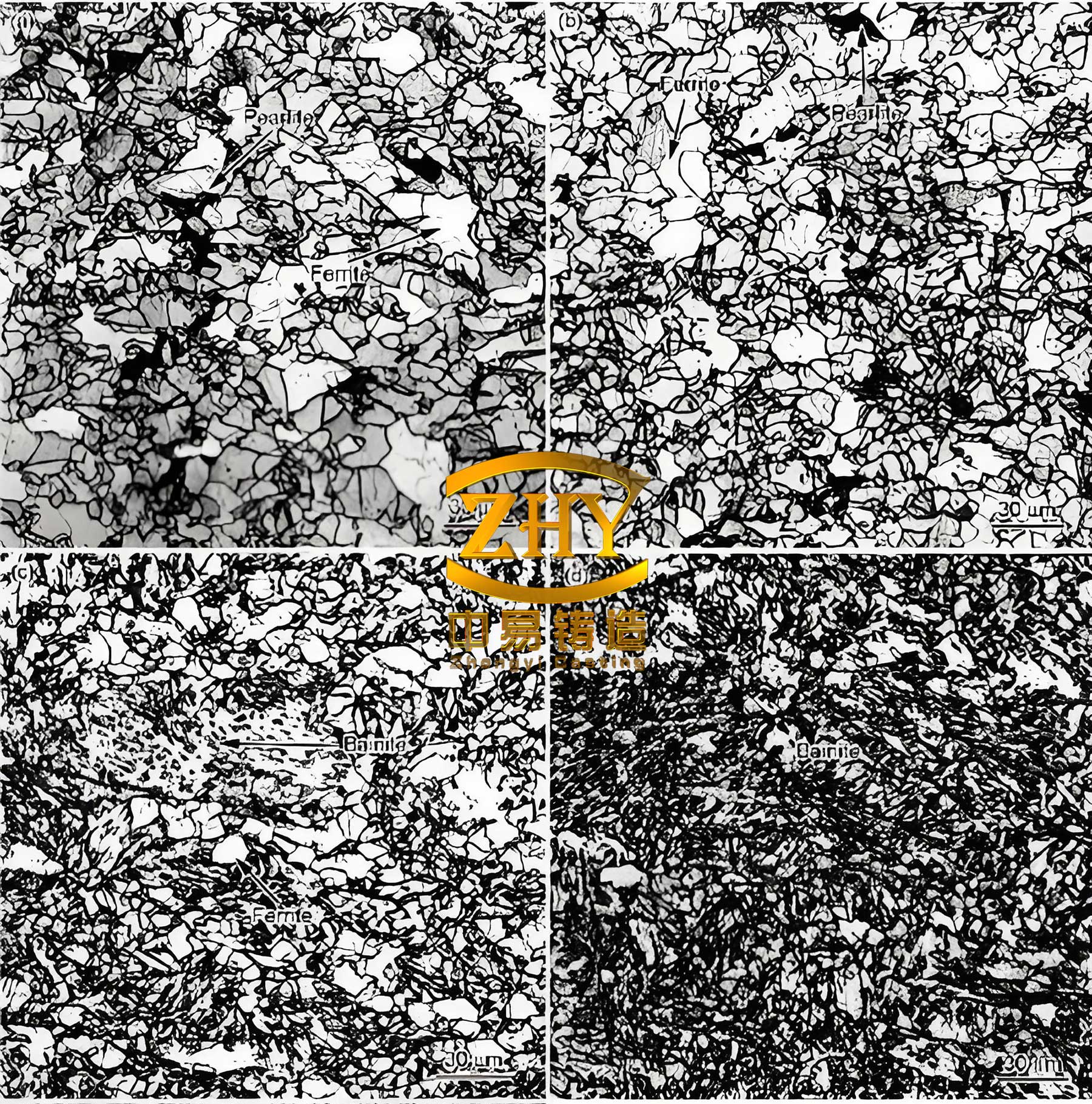
The microstructure of spheroidal graphite cast iron is pivotal in determining its response to welding. The image above illustrates the typical nodular graphite structure, which is essential for the material’s ductility. During welding, the heat cycle can alter this morphology in the HAZ. To quantify the thermal cycle, we consider the temperature field around a moving point heat source. For a quasi-steady state, the temperature distribution $ T(r,t) $ can be modeled with Rosenthal’s equation for a thick plate:
$$ T – T_0 = \frac{Q}{2 \pi k r} \exp\left(-\frac{v(r+x)}{2\alpha}\right) $$
where $ r $ is the radial distance from the heat source, $ v $ is the travel speed, $ \alpha $ is the thermal diffusivity, and $ x $ is the coordinate in the travel direction. This model helps estimate the time-temperature profile in the HAZ, which governs phase transformations. For spheroidal graphite cast iron, avoiding the critical cooling rate that leads to cementite formation is key. The critical cooling rate $ \dot{T}_\text{crit} $ between 800°C and 500°C can be empirically derived for spheroidal graphite cast iron compositions.
Our process successfully controlled this cooling rate through low heat input and intermittent welding. The weld metal chemistry, dominated by nickel, suppressed carbon migration and carbide precipitation. The dilution of base metal into the weld pool was minimized by technique. We can express dilution $ D $ as:
$$ D = \frac{A_b}{A_b + A_f} \times 100\% $$
where $ A_b $ is the cross-sectional area of fused base metal and $ A_f $ is the area of filler metal. By using stringer beads with minimal oscillation, we kept $ D $ below 30%, limiting the carbon pickup in the weld metal.
The effectiveness of the repair was validated through non-destructive testing and subsequent machining. Dye penetrant inspection revealed no surface cracks. The machined surface in the repaired zone exhibited uniform hardness, measured to be 180–210 HBW, consistent with the base spheroidal graphite cast iron. The final assembly confirmed proper fit and function, meeting all operational loads. This case underscores that with meticulous procedure design, welding can be a viable repair method for spheroidal graphite cast iron components, even those with stringent dimensional constraints.
In conclusion, the weld repair of the QT500-7 spheroidal graphite cast iron wheel hub was a success, achieved through a deep understanding of the material’s weldability challenges and the application of a disciplined cold welding technique. The selection of a nickel-iron electrode provided the necessary ductility and strength, while the segmented welding with interpass peening managed thermal stresses and prevented white iron formation and cracking. This approach not only salvaged an expensive component but also demonstrated the feasibility of repairing complex spheroidal graphite cast iron parts in a production environment. Future work could involve finite element simulation of the thermal stresses and optimized welding sequences for larger spheroidal graphite cast iron structures.