
In my years of experience specializing in the production of heavy-section castings, few challenges are as demanding as the manufacturing of large, complex cylinder castings from ductile cast iron. These components, critical for power generation equipment like steam turbines, are subjected to extreme operational stresses and require impeccable internal integrity. The journey from molten metal to a sound casting is fraught with potential defects, and the design of the pouring system is arguably the most decisive factor in this journey. This article details a systematic, calculation-driven methodology I have developed and refined for designing reliable gating systems, specifically for large ductile cast iron inner cylinder castings, focusing on a differential pouring technique to ensure superior quality.
The Critical Challenge of Large Ductile Cast Iron Castings
The unique properties of ductile cast iron – its excellent strength-to-weight ratio, good machinability, and damping capacity – make it the material of choice for these components. However, its casting process introduces specific hurdles. Following spheroidization and inoculation treatments, the temperature of the ductile cast iron melt drops significantly, increasing its viscosity and the risk of premature solidification in thin sections or long flow paths. More critically, the treated melt is highly prone to oxidation, leading to the formation of secondary dross and slag inclusions if the flow is turbulent.
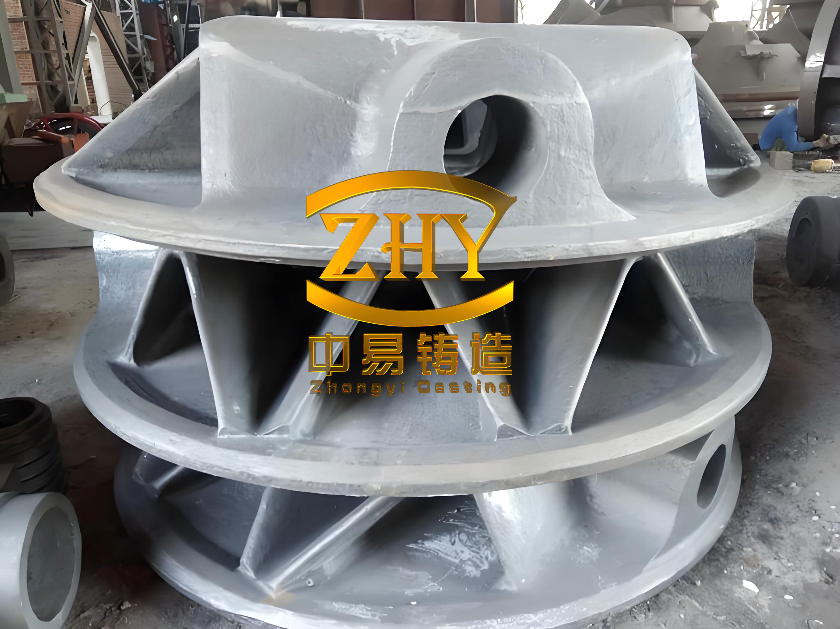
For a large inner cylinder casting, which can weigh over 40 tons and feature extensive surface areas, complex internal geometries, and numerous chilling inserts for directional solidification, the consequences of poor gating are severe. The final product must undergo and pass rigorous 100% non-destructive testing, including Magnetic Particle (MT) and Ultrasonic Testing (UT) to Level 2 standards. Defects like shrinkage porosity, slag inclusions, sand erosion, and cold shuts are unacceptable. Therefore, the primary objective of the gating system is no longer just to fill the mold but to do so in a calm, controlled, and predictable manner that minimizes turbulence, oxidation, and temperature gradients.
Evolution Beyond Empirical Design
Traditionally, the design of gating systems for such castings was heavily reliant on empirical rules and iterative correction. Initial parameters for sprue, runner, and ingate dimensions were chosen based on past experience or handbook ratios. A prototype would be poured, cut, and inspected, and the gating would be adjusted based on the defects found. This trial-and-error approach is not only time-consuming and costly but also lacks consistency. Slight variations in patternmaking, molding, or melting can lead to different outcomes with the same nominal gating design.
Driven by the need for higher reliability and first-pass success, I developed a physics and calculation-based approach. This method integrates fundamental hydraulic principles, thermal calculations, and modern 3D simulation tools to define the gating system parameters *before* the first mold is made, with the specific goal of eliminating turbulence-related and shrinkage defects in ductile cast iron.
Foundations of the Pouring System Design
System Type Selection
The choice of gating system type is the first critical decision. For large, quality-critical ductile cast iron castings, a bottom-gating, open-type system is non-negotiable. The reasons are clear:
- Minimized Turbulence: Filling the mold from the bottom allows the metal to rise calmly, preventing splashing and aspiration of air and mold gases.
- Reduced Oxidation: Low entry velocity from the ingates minimizes re-oxidation of the already-treated ductile cast iron melt.
- Favorable Temperature Gradient: The first metal to enter the mold cavity, which is cooler, resides at the bottom, while hotter metal from later in the pour remains higher up, promoting directional solidification from the bottom (feeding zone) to the top (risers).
The main drawback of a bottom-gating system is its poor slag-trapping capability, as any slag entering the system flows directly into the cavity. This necessitates the incorporation of effective slag filtration within the runner system.
Structural Configuration: The Multi-Sprue Differential Concept
For a massive cylinder casting weighing approximately 49 tons, relying on a single sprue is impractical. It would require an impractically large cross-section and result in excessive pouring times, leading to severe temperature loss. The solution is a multi-sprue system. However, simply having multiple sprues open simultaneously can cause confluence turbulence in the cavity. To solve this, I employ a Differential Pouring strategy using a multi-tiered sprue arrangement.
The system is conceptually divided into two tiers:
Tier 1 (Primary): A central sprue that begins filling the mold cavity.
Tier 2 (Secondary): Two or more auxiliary sprues that are opened after a precisely calculated time delay.
The goal is to synchronize the metal flow fronts from all sprues so they meet and merge without one stream overriding another, which would cause cold shuts and oxide laps. The key innovation is using the casting’s 3D geometry to calculate the exact timing for this synchronization.
The Calculation-Driven Design Methodology
Let’s walk through the design process for a representative 49-ton ductile cast iron inner cylinder with a nominal wall thickness of 45 mm.
Step 1: Determining the Optimal Pouring Time
The total pouring time must be balanced. Too fast, and turbulence increases; too slow, and the metal temperature drops excessively, risking mistuns and poor feeding. An empirical formula suitable for large castings provides a starting point:
$$ t_{opt} = f \cdot \sqrt[3]{G_{casting}} \cdot \sqrt{\delta} \cdot \frac{1}{\sqrt[3]{n}} $$
Where:
$t_{opt}$ = Optimal pouring time (s)
$f$ = Material factor (for ductile cast iron, typically 1.0-1.2; we use 1.0)
$G_{casting}$ = Casting weight (kg) = 49,000 kg
$\delta$ = Characteristic wall thickness (mm) = 45 mm
$n$ = Number of functional sprue units (max 3)
Applying these values:
$$ t_{opt} = 1.0 \cdot \sqrt[3]{49000} \cdot \sqrt{45} \cdot \frac{1}{\sqrt[3]{3}} \approx 132 \text{ seconds} $$
Thus, our total system should be designed to fill the mold in approximately 132 seconds.
Step 2: Sizing the Sprue and Ingate Networks
We now use 3D modeling software to analyze the casting’s geometry. The mass distribution reveals that the central, lower portion of the casting fed primarily by the Tier 1 sprue weighs about 12 tons. The remaining ~37 tons of metal will be divided between the two Tier 2 sprues (approximately 18.5 tons each).
The next step is to determine the sprue diameters. This is based on the flow rate characteristics of stopper-rod controlled pouring ladles (or pouring basins). The relationship between sprue diameter ($S_{sprue}$), pouring head height, and flow time for a given weight is established through fluid mechanics:
$$ Q = C_d \cdot A \cdot \sqrt{2gh} $$
Where $Q$ is the volumetric flow rate, $C_d$ is the discharge coefficient, $A$ is the sprue cross-sectional area, $g$ is gravity, and $h$ is the metallostatic head. For practical foundry use, this is simplified into empirical tables or formulas derived for standard ladle sizes (e.g., 12-ton, 18-ton ladles).
To achieve the target pouring time of ~132s for the Tier 1 section, a sprue diameter of 90 mm is selected from the ladle performance charts, giving a calculated fill time of 128 seconds. For the larger Tier 2 sprues (each handling ~18.5 tons), a diameter of 110 mm yields a fill time of 115 seconds, which is also acceptable.
The ingate area must be larger than the sprue area to maintain an open (non-pressurized) system that reduces velocity. For Tier 1, we use 6 ingates, each 60 mm in diameter. For each Tier 2 sprue, we use 12 ingates of the same diameter. The area ratios are:
- Tier 1: Sprue Area : Total Ingate Area = 1 : 2.7
- Tier 2: Sprue Area : Total Ingate Area = 1 : 3.6
These ratios ensure a calm, laminar flow of ductile cast iron into the mold cavity.
Step 3: The Core Innovation – Calculating the Differential Pouring Delay
This is the most critical calculation to prevent back-flow and confluence turbulence. The objective is to have the metal fronts from all sprues meet at a predetermined “confluence line” within the casting cavity simultaneously.
- Using the 3D CAD model, we define the theoretical flow path and calculate the volume (and thus mass) of the casting cavity that would naturally be filled by the Tier 1 sprue before the metal reaches the height where the Tier 2 ingates are located. This region is identified.
- We then calculate the mass of metal below this confluence line that is intended to be supplied by each Tier 2 sprue.
- From the ladle flow-rate data, we determine two key times:
- $t_1$: The time for the Tier 1 sprue to pour the mass of metal required to reach the confluence line.
- $t_2$: The time for a single Tier 2 sprue to pour the mass of metal it contributes below the confluence line.
The differential delay time $T_{delay}$ is then:
$$ T_{delay} = t_1 – t_2 $$
For our example cylinder:
Mass contributed by Tier 1 sprue to confluence line, $G_{1\_contributed}$ = 5.2 tons.
Mass contributed by one Tier 2 sprue below confluence line, $G_{2\_contributed}$ = 4.2 tons.
From flow charts: $t_1 \approx 30$ seconds and $t_2 \approx 15$ seconds.
Therefore:
$$ T_{delay} = 30s – 15s = 15 \text{ seconds} $$
This means the stopper for the Tier 1 sprue is opened first. After a delay of 15 seconds, the stoppers for the two Tier 2 sprues are opened. This timing ensures the metal fronts coalesce smoothly, drastically reducing the risk of oxide formation at the merge point.
Step 4: Integrating Slag Filtration
To compensate for the weak slag-trapping of a bottom-gate system, ceramic foam filters are placed in the horizontal runners. The number of filters is determined by their rated throughput. Assuming a standard filter plate (e.g., 300x150x40 mm) can handle a maximum of 2.2 tons of ductile cast iron:
For Tier 1 system (12 tons): $N_{filters\_T1} = 12 / 2.2 \approx 5.45 \rightarrow$ Use 6 filters.
For each Tier 2 system (18.5 tons): $N_{filters\_T2} = 18.5 / 2.2 \approx 8.4 \rightarrow$ Use 9 or 10 filters per system.
This ensures the molten ductile cast iron is effectively cleaned before entering the casting cavity.
| System Tier | Function | Metal Weight (tons) | Sprue Diameter (mm) | Number & Diameter of Ingates | Area Ratio (Sprue:Ingates) | Calculated Fill Time (s) | Number of Filters | Pouring Delay (s) |
|---|---|---|---|---|---|---|---|---|
| Tier 1 | Primary Fill | 12 | 90 | 6 x Ø60 mm | 1 : 2.7 | 128 | 6 | 0 (Starts first) |
| Tier 2 | Secondary Fill | 18.5 (each) | 110 | 12 x Ø60 mm | 1 : 3.6 | 115 (each) | 10 (each) | +15 (After Tier 1) |
Virtual Validation and Production Results
Before committing to expensive tooling and melt, the entire system is modeled and simulated using dedicated casting simulation software like MAGMAsoft or ProCAST. The simulation includes the full gating, filters, casting, feeders, and chills. The software predicts:
- Fill Pattern: Verifies the smooth, bottom-up fill and the synchronized merging of metal fronts from the different sprues.
- Temperature Distribution: Assesses the thermal gradient at the end of filling to ensure it supports directional solidification towards the risers.
- Shrinkage Porosity Risk: Identifies potential isolated hot spots where shrinkage could occur, allowing for adjustments in chill placement or riser size.
In the simulation for this design, the predicted fill was exceptionally calm, and the solidification pattern showed a clear progression from the thick sections (fed by chills and ingates) towards the top risers. The areas of predicted porosity risk were minimal and confined to non-critical zones or were eliminated by minor chill adjustments.
The ultimate validation comes from production. Castings produced using this calculated differential pouring system have consistently shown a dramatic improvement in internal quality. The controlled fill minimizes slag and dross formation. The optimized thermal gradients reduce shrinkage defects. Post-casting, the components undergo full-body NDT inspection. The results have been excellent, with the castings reliably meeting the stringent Level 2 MT and UT acceptance criteria. The occurrence of rejectable defects related to the pouring process has been reduced to a negligible level.
Broader Implications and Conclusion
This calculation-based methodology for designing gating systems, particularly the differential pouring technique, represents a significant advancement over traditional empirical approaches for large, high-integrity ductile cast iron castings. Its benefits are manifold:
- Predictability and First-Pass Success: By defining parameters through physics and geometry, the process becomes reproducible and less dependent on individual craft, reducing costly and time-consuming trial runs.
- Quantifiable Design: Every aspect – pouring time, sprue size, delay timing, filter count – is backed by a calculation, providing a clear rationale for the design choices.
- Optimized Material Properties: A calm fill and controlled solidification preserve the metallurgical quality of the ductile cast iron, ensuring the graphite nodule structure and matrix are not compromised by turbulence or shrinkage.
- Wide Applicability: While detailed for a cylinder, the principles are directly applicable to other large, complex castings in ductile cast iron, such as valve bodies, machine tool beds, and wind turbine hubs.
The future of heavy casting lies in this fusion of fundamental engineering principles, advanced 3D modeling, and sophisticated simulation. For ductile cast iron, a material whose potential is only fully realized through flawless processing, such a disciplined approach to gating system design is not just beneficial – it is essential for achieving the reliability and performance demanded by modern industry.