
In the realm of metal casting, sand casting remains a predominant and versatile method for producing complex components, especially for non-ferrous alloys like aluminum. The ability to create intricate shapes with relatively low tooling cost makes it ideal for both batch and mass production. This article details a comprehensive study on the process design and numerical simulation for the sand casting of a medium-sized, thick-walled aluminum alloy gear box body, a critical component in mechanical transmission systems. The focus is on developing a robust casting process to minimize defects common in sand casting products, such as shrinkage porosity, cold shuts, and gas entrapment. Through meticulous design and advanced simulation, we aim to establish a reliable manufacturing protocol for high-quality sand casting products.
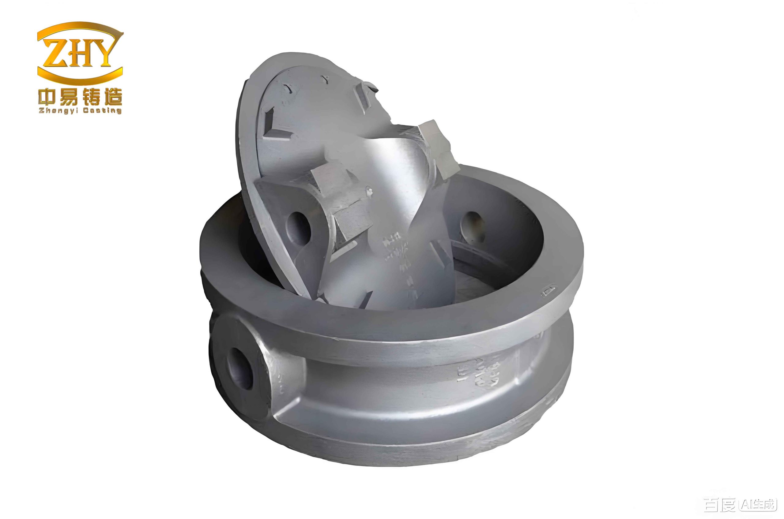
The gear box body in question is fabricated from AlSi7Mg0.3 aluminum alloy, known for its good castability, strength, and weight-saving properties. The part’s irregular external geometry, varying wall thickness (primarily 10-12 mm), internal cavities, ribs, and bosses present significant challenges for achieving sound casting. The overall envelope dimensions are 751 mm × 400 mm × 291 mm, classifying it as a medium-sized casting. The production volume was specified as batch production, necessitating a process that balances quality with efficiency. Our objective was to design a sand casting process that ensures dimensional accuracy and mechanical integrity while being economically viable for repeated runs.
We initiated the project by creating a detailed three-dimensional digital model of the gear box body. Utilizing Siemens NX (UG) software, we constructed the model from the ground up. The process began with sketching the primary external contours in the sketch module. These profiles were then extruded, revolved, and drafted to form the solid external shape. The complex internal cavity, comprising several curved surfaces, was modeled using the ‘curve through mesh’ and surface modeling tools to ensure an accurate representation of the core print regions. This digital twin, as shown conceptually in the figure below, served as the foundation for all subsequent process design and simulation activities. Accurate 3D modeling is paramount for simulating the behavior of molten metal and for designing the tooling required for sand casting products.
The foundation of any successful casting lies in its process design. After a thorough analysis of the component’s geometry and technical requirements, we selected green sand molding as the primary method. However, to achieve higher dimensional accuracy and surface finish suitable for batch production, we opted for a precision core assembly approach using no-bake resin sand. Alkaline phenolic resin-bonded sand was chosen for its excellent collapsibility and dimensional stability. The process flowchart encompasses key stages: pattern making, sand preparation and mixing, molding, core making, mold assembly, melting, pouring, shakeout, cleaning, and final inspection. For the mold and core surfaces, we specified an alcohol-based refractory coating to seal surface porosity and create a thermal barrier, thereby improving the surface quality of the final sand casting products. Any minor cracks or imperfections in the molds or cores were repaired with specialized patching compounds.
A critical decision was the molding method. Given the part’s external ribs and bosses with varying orientations, a conventional two-part flask mold would be difficult to draw. Therefore, we adopted a cold-box, precision core assembly technique. This method involves creating the entire mold cavity from multiple interlocking sand cores, eliminating the need for a traditional flask. It significantly reduces sand waste, improves dimensional consistency, and lowers machining allowances for sand casting products. The parting line was strategically placed on the upper surface of a central rib on the front side of the box, dividing the mold into an upper and a lower section. Additionally, a side core was designed to form the intricate ribs on the left side, and a large internal core was created to define the complex central cavity. The assembly sequence was established as: lower mold section -> internal core -> side core -> upper mold section. This core assembly strategy is highly effective for producing complex sand casting products.
The design of the gating and risering system is crucial for defect-free castings, especially for aluminum alloys which have high shrinkage propensity and are prone to oxidation. The gating system must ensure a tranquil, non-turbulent fill to minimize slag and gas entrainment. We designed a stepped runner system located at the parting plane for ease of molding. The system comprised one sprue, one horizontal runner, and two ingates. Ceramic foam filters were placed at two critical junctions: between the pouring cup and the sprue, and between the sprue and the runner. These filters effectively trap non-metallic inclusions, a common issue in sand casting products. The ingates were positioned on machinable surfaces of the casting for easy removal post-casting. A slag trap was incorporated near the ingates to further improve metal cleanliness.
The sizing of the gating system channels is based on hydraulic principles. The smallest cross-sectional area in the system controls the pouring rate and is typically at the sprue base. We used the following empirical formula to calculate the minimum required area, $A_{smin}$:
$$A_{smin} = \frac{G_L}{K t \sqrt{H_P}}$$
where $G_L$ is the total poured weight of metal (approximately 45 kg for this casting including the gating system), $K$ is a fluidity factor for aluminum alloy (taken as 0.9), $t$ is the pouring time in seconds, and $H_P$ is the mean metallostatic pressure head in cm. The pouring time was estimated using another empirical relation for medium steel castings, adapted for aluminum:
$$ \tau = B \delta \sqrt[P]{m_n} $$
Here, $m_n$ is the casting mass, $\delta$ is the characteristic wall thickness, and $B$ and $P$ are coefficients derived from experience. For our aluminum casting, a pouring time of 16-18 seconds was calculated, resulting in a metal rise velocity of about 33 mm/s within the mold cavity. Using these values in the first formula yielded an $A_{smin}$ of approximately 4.1 cm². We selected a standard sprue with a bottom diameter of 25 mm, giving an area of 4.9 cm². Following recommended gating ratios for aluminum sand casting products (Sprue : Runner : Ingate = 1 : 2 : 2), we determined the dimensions: total runner cross-section = 9.8 cm², and each ingate cross-section = 4.9 cm². The lengths were derived from the mold layout: ingate length = 223 mm, runner length = 382 mm, sprue height = 270 mm.
To compensate for solidification shrinkage, risers are essential. We placed three cylindrical risers on top of the casting at locations identified as thermal centers (hot spots) based on geometric analysis. Furthermore, in areas where riser placement was impractical, such as isolated thick sections and junction points of ribs, we planned to use external chills. Chills are metallic inserts that accelerate localized cooling, promoting directional solidification towards the risers. The table below summarizes the key gating and risering parameters.
| Parameter | Value | Description/Calculation Basis |
|---|---|---|
| Pouring Temperature | 700 – 720 °C | Optimal range for AlSi7Mg0.3 to minimize gas pick-up and oxidation. |
| Estimated Pouring Time ($t$) | 16-18 s | Calculated from empirical formula $\tau = B \delta \sqrt[P]{m_n}$. |
| Metal Rise Velocity | ~33 mm/s | Derived from casting height and pouring time. |
| Minimum Choke Area ($A_{smin}$) | 4.1 cm² | Calculated using $A_{smin} = G_L / (K t \sqrt{H_P})$. |
| Sprue Bottom Diameter | 25 mm | Chosen standard size, area = 4.9 cm² > $A_{smin}$. |
| Gating Ratio (S:R:I) | 1 : 2 : 2 | Standard for aluminum sand casting products. |
| Runner Cross-sectional Area | 9.8 cm² | 2 × Sprue area. |
| Each Ingate Cross-sectional Area | 4.9 cm² | Equal to sprue area. |
| Number of Risers | 3 | Placed on top thermal centers. |
| Chill Usage | Yes | At isolated thick sections and junctions. |
To validate our process design and predict potential defects, we employed numerical simulation using AnyCasting software. This powerful tool allows us to visualize the filling and solidification processes, identifying regions susceptible to shrinkage, porosity, and cold shuts before any physical tooling is made. The 3D CAD model was imported, and the simulation domain was set up including all molds, cores, the gating system, risers, and chills. The material properties for AlSi7Mg0.3 were assigned from the software’s database, including thermal conductivity, specific heat, latent heat of fusion, and solid fraction characteristics. The initial conditions were set with a pouring temperature of 710°C and a mold initial temperature of 25°C. The boundary conditions accounted for heat transfer at the mold-metal and core-metal interfaces.
The filling simulation confirmed that our gating design provided a smooth, progressive fill without excessive turbulence or air entrapment. The metal front advanced steadily, and the runners and filters effectively distributed the flow. The final areas to fill were the risers, which is desirable as it concentrates any last-stage slag or oxide films there, away from the casting itself—a critical quality aspect for sand casting products.
The core of the analysis was the solidification simulation. The temperature distribution at various time steps revealed the solidification pattern. As expected, the thinner external walls solidified first, followed by thicker sections and the internal core regions. The thermal gradient showed that the last points to solidify were located within the complex internal cavity of the gear box body, specifically at the junctions of walls and ribs. The total simulated solidification time was approximately 48 minutes (2880 seconds). The software’s defect prediction module, based on the Niyama criterion (a function of thermal gradient $G$ and cooling rate $R$), flagged these last-to-solidify zones as high-probability locations for shrinkage porosity. The Niyama criterion $N_y$ is given by:
$$ N_y = \frac{G}{\sqrt{\dot{T}}} $$
where $\dot{T}$ is the cooling rate. Regions with $N_y$ below a critical threshold are prone to microporosity.
The initial simulation run, performed without the planned chills, clearly predicted shrinkage defects in the internal cavities. This aligned with our theoretical analysis. To mitigate this, we modified the simulation model by adding steel chills at the identified hot spots on the external surfaces adjacent to the problem areas. Re-running the simulation demonstrated a significant improvement. The chills acted as heat sinks, altering the solidification sequence. They created steeper thermal gradients, directing solidification fronts more effectively toward the risers. The revised defect prediction plot showed a marked reduction in the size and probability of shrinkage cavities in the internal sections. The table below contrasts key solidification parameters between the two scenarios.
| Parameter / Observation | Scenario A: Without Chills | Scenario B: With Chills |
|---|---|---|
| Last Solidification Time | ~2613 s | ~2450 s |
| Primary Defect Location | Internal cavity junctions, thick ribs | Greatly reduced in internal cavities; minor risk at riser necks |
| Predicted Defect Severity (Niyama Criterion) | High in core regions (Low $N_y$ values) | Low in casting body; acceptable $N_y$ values in most areas |
| Thermal Gradient at Hot Spots | Relatively flat | Steepened due to directional cooling from chills |
| Riser Efficiency | Moderate; risers could not feed deep internal hot spots | Improved; solidification path better directed towards risers |
To quantify the thermal behavior, we can analyze the heat transfer. The fundamental equation governing heat conduction during solidification is the Fourier equation with a source term for latent heat release:
$$ \rho c_p \frac{\partial T}{\partial t} = \nabla \cdot (k \nabla T) + \rho L \frac{\partial f_s}{\partial t} $$
where $\rho$ is density, $c_p$ is specific heat, $k$ is thermal conductivity, $T$ is temperature, $t$ is time, $L$ is latent heat, and $f_s$ is solid fraction. The addition of chills modifies the boundary condition at the chill-casting interface, significantly increasing the heat flux $q”$ from that localized area:
$$ q” = h_{interface} (T_{casting} – T_{chill}) $$
where $h_{interface}$ is the interfacial heat transfer coefficient, which is much higher for a metal-chill contact than for a metal-sand contact. This enhanced extraction is what accelerates solidification at targeted spots.
The simulation provided not just a binary pass/fail result but a detailed map of solidification sequences, temperature gradients, and cooling rates. This data is invaluable for optimizing the process for sand casting products. For instance, we could adjust the size or placement of risers based on the feeding distance revealed by the simulation. The feeding distance $FD$ for a plate-like section can be estimated as:
$$ FD = C \cdot \sqrt{V/A} $$
where $V$ is volume, $A$ is surface area, and $C$ is a material constant. Our simulation helped verify that our riser placements were within effective feeding ranges after chill application.
Based on the simulation-validated design, we finalized the complete casting process specifications. The key elements are: Material: AlSi7Mg0.3; Process: No-bake resin sand, cold-box core assembly; Gating: Filtered stepped runner with two ingates; Risering: Three top risers; Auxiliary Cooling: Strategic placement of external steel chills; Pouring Temperature: 710°C ±10°C. This integrated approach ensures the production of sound sand casting products with minimal internal defects.
This case study underscores the critical role of integrated process design and simulation in modern foundry practice, especially for complex sand casting products. The sequential approach—3D modeling, empirical design, and then rigorous numerical simulation—forms a virtuous cycle for optimization. The simulation acted as a virtual prototyping tool, saving significant time and cost that would have been spent on trial-and-error physical castings. It allowed us to proactively identify and solve the problem of internal shrinkage in the gear box body by incorporating chills. The final process is robust, repeatable, and suitable for batch production, yielding high-quality aluminum alloy sand casting products with reliable mechanical properties. Future work could involve further optimization of the chill design (size, material) and investigation of the effects of different sand binder systems on the dimensional accuracy and surface finish of such sand casting products. The methodology presented here is widely applicable to the development of manufacturing processes for a vast array of intricate sand casting products across automotive, aerospace, and machinery sectors.