
In the traditional realm of sand casting for steel and iron castings, the use of resin-bonded sand with wooden patterns in molding boxes to form the product cavity is standard practice. After pouring molten metal, a rough casting is obtained. Traditionally, the molding boxes (flasks) are standard right-angled quadrilaterals or other regular shapes, while the castings produced within them can be of nearly any contour. During molding, the entire volume between the pattern and the flask walls is filled with resin sand. This filled resin sand constitutes one of the primary raw material costs in the sand casting process. This article aims to present the development and application of a flexible, dismountable, and reusable modular tooling system. This system is designed to occupy the space between the casting pattern and the flask, thereby dramatically reducing the consumption of fresh resin sand and lowering production costs for large sand casting products.
1. Challenges in Conventional Sand Casting Practice
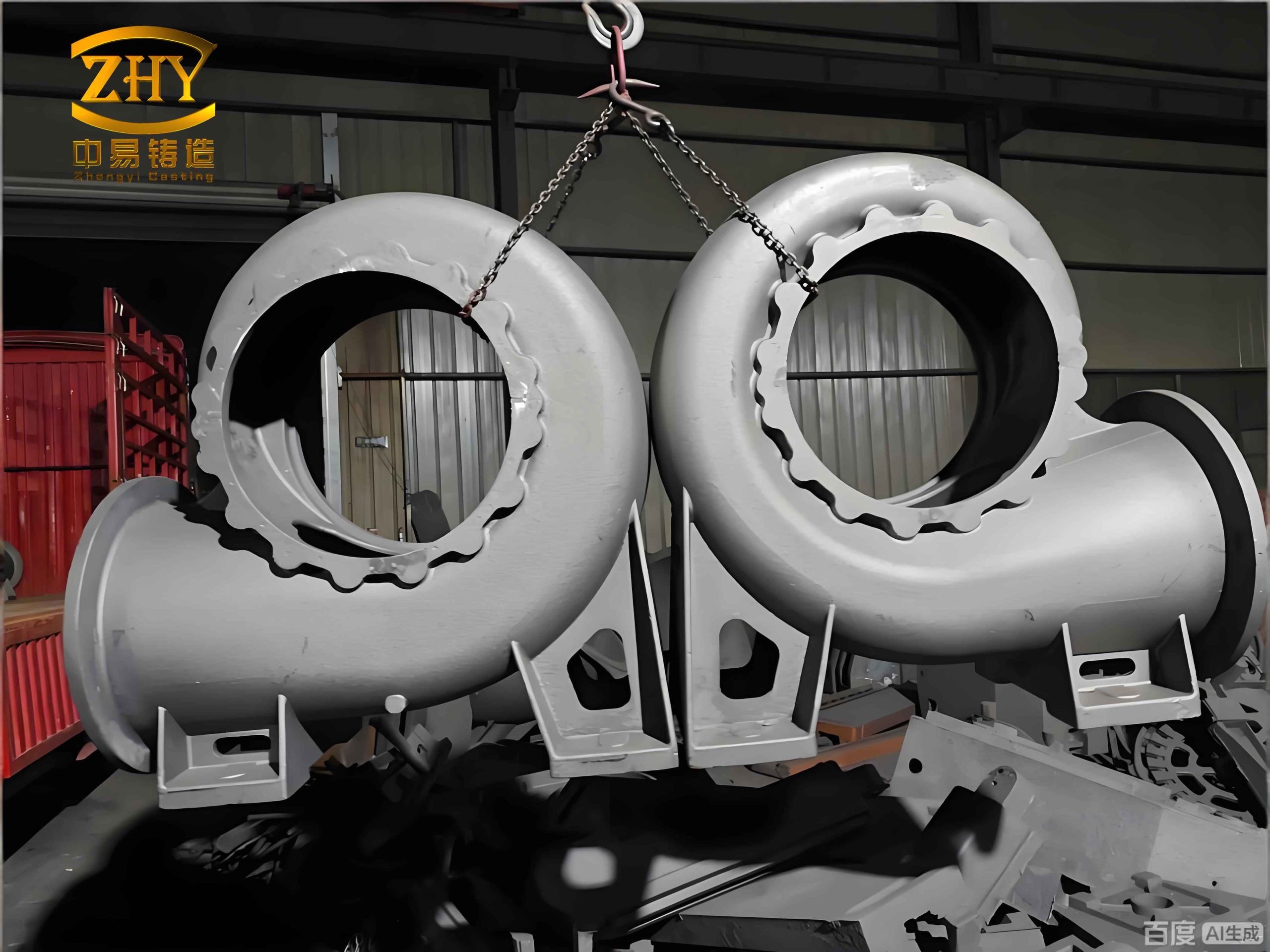
The limitations of the traditional method become acutely apparent with large, thin-walled sand casting products. Let us consider a typical hydroelectric power station runner ring as an example. Such a product may have major contour dimensions of φ4,600 mm × 1,100 mm. These components are characterized by their enormous structural envelope and relatively small wall thickness.
In conventional practice, to accommodate the large external contour of such a casting, the entire volume, both internally and externally around the pattern, is rammed with resin-bonded sand to create the required mold cavity. A schematic representation of this approach is shown below, illustrating the massive volume of sand employed.
This method leads to two significant drawbacks for these sand casting products:
- Prohibitively High Sand Consumption and Cost: The weight of resin sand used (both internal and external) often exceeds 13 times the weight of the final metal casting itself. Since this sand is a consumable, single-use item in the process, it represents a non-recoverable cost. In many cases, the cost of resin sand can account for up to 20% of the total production cost of the casting, severely eroding profit margins. The key metric here is the Sand-to-Metal Ratio (STR), defined as:
$$ STR = \frac{M_s}{M_c} $$
where $M_s$ is the mass of sand used and $M_c$ is the mass of the finished casting. For traditional large ring casting methods, STR values of 13 or higher are common. - Increased Risk of Casting Defects: The excessive thickness of the sand mold, particularly in large sections, impedes the escape of gases generated during the pouring process as the resin binder pyrolyzes. This difficulty in venting can lead to gas porosity and slag inclusions in the final casting, compromising its integrity and increasing scrap rates.
Therefore, there is a compelling need for a reusable, universal tooling solution designed specifically for large steel castings. The primary objectives are to drastically reduce resin sand consumption, lower the overall cost of sand casting products, and improve casting quality by facilitating better gas escape.
2. Design and Fabrication of the Modular Tooling System
Our approach centers on creating a system of standardized, interlocking blocks that can be assembled into various polygonal shapes to closely fit the internal or external contours of a pattern, replacing a large volume of sand.
2.1 Standard Block Design
The fundamental unit of the system is a standard block. Its design specifications are as follows:
- Material: Plain carbon steel plate.
- Plate Thickness: 10 mm.
- Block Height (H): 500 mm, designed to match the height of a standard molding flask layer.
- Block Width (L): Two standard widths are manufactured: 800 mm and 1,000 mm, providing flexibility for different cavity sizes.
- Reinforcement: 20 mm × 20 mm steel bars are welded to the plate as stiffening ribs to ensure structural rigidity during sand ramming and metal pouring.
- Connection System: Short lengths of steel pipe (e.g., outer diameter 50 mm, inner diameter 40 mm) are welded to the vertical edges of the block. These serve as sockets for connecting pins.
- Handling Feature: An Ø80 mm hole is cut near the top of the plate to allow for easy lifting and positioning using an overhead crane.
The design of a single standard block can be summarized by the following schematic parameters. The connection pipes are symmetrically placed to allow assembly from both sides.
$$ \text{Block Volume}_{(empty)} = L \times H \times t_{\text{plate}} + V_{\text{stiffeners}} + V_{\text{pipes}} $$
Where $t_{\text{plate}}$ is the plate thickness. The actual volume displaced in the mold is the envelope volume $L \times H \times D$, where $D$ is the block’s depth (not solely the plate thickness, as it includes pipes and ribs).
2.2 Connection Pin Design
To assemble blocks, solid round steel pins are used. A typical pin is made from Ø30 mm round bar, with one end shaped for easier driving and extraction (tapered or chamfered), and the main body providing a snug fit within the connecting pipes of adjacent blocks.
The pin acts as a shear key, transferring loads between blocks. The required pin diameter $d_{pin}$ can be estimated based on the shear stress $\tau$ from the lateral pressure of the rammed sand $P_{sand}$ over the block area $A_{block}$:
$$ d_{pin} \geq \sqrt{ \frac{4 \cdot P_{sand} \cdot A_{block}}{n \cdot \pi \cdot \tau_{allowable}} } $$
where $n$ is the number of pins per connection. For a 1,000 mm wide, 500 mm high block, this calculation ensures sufficient strength.
2.3 Assembly into Polygonal Structures
The core innovation lies in the blocks’ ability to form closed polygons. By connecting multiple blocks end-to-end via their pins and pipe sockets, various shapes can be created. The geometry is straightforward: for a regular polygon with $n$ sides, each internal angle $\theta$ is:
$$ \theta = \frac{180(n-2)}{n} $$
When two blocks are connected, their plates form this interior angle. The connection system must allow for this angular flexibility, which is achieved by the clearance between the pin and pipe.
For example:
- A hexagonal assembly ($n=6, \theta=120^\circ$) requires 6 blocks.
- An octagonal assembly ($n=8, \theta=135^\circ$) requires 8 blocks of the appropriate width.
The perimeter $P$ of the assembled polygon should approximate the circumference of the casting cavity $C_{cavity}$:
$$ P = n \cdot L \approx C_{cavity} = \pi \cdot D_{cavity} $$
This allows us to select the block width $L$ and number $n$ to best fit a given cavity diameter $D_{cavity}$.
| Block Width (L) | Block Height (H) | Typical Polygon | Number of Blocks (n) | Approx. Internal Dia. (mm) |
|---|---|---|---|---|
| 1000 mm | 500 mm | Octagon | 8 | ~4000 |
| 800 mm | 500 mm | Decagon | 10 | ~2550 |
| 1000 mm | 500 mm | Hexagon | 6 | ~1900 |
3. Application Methodology and Quantitative Benefits
The implementation of this modular tooling system transforms the molding process for large, ring-shaped sand casting products.
3.1 Step-by-Step Molding Process
- Pattern and Flask Placement: The wooden pattern for the ring casting is positioned on the molding floor. The outer molding flask is placed around it.
- Layered Assembly and Sand Ramming: The process proceeds in layers corresponding to the block height (500 mm).
- For the first layer, the appropriate polygon (e.g., an octagon for a ~Ø4000 mm cavity) is assembled from standard blocks and placed inside the pattern’s cavity.
- The annular space between the outer surface of the pattern and the flask is rammed with resin sand and compacted.
- The space inside the assembled polygon block structure is not filled with resin sand. Instead, it may be filled with dry, un-bonded sand (which is cheap and recyclable) or supported with internal steel bracing. This is the critical area of sand saving.
- Repetition for Subsequent Layers: Once the first layer is complete, the next flask section is placed on top. A new layer of the modular polygon is assembled on top of the first, and the ramming process is repeated. This continues until the full mold height is achieved.
- Reclamation and Reuse: After pouring, cooling, and shakeout, the modular blocks are recovered undamaged. The connecting pins are removed, and the blocks are cleaned for reuse in the next casting job. The dry sand inside the assembly is also recovered by the standard sand reclamation system.
3.2 Economic and Technical Analysis
The benefits are quantified using the example of the Ø4,600 mm x 1,100 mm hydroelectric ring. Let’s define the following variables for analysis:
- $V_{total}$: Total mold cavity volume between pattern and flask.
- $V_{pattern}$: Volume of the pattern (approximating casting volume).
- $V_{sand\_old}$: Volume of resin sand used in the old method ≈ $V_{total} – V_{pattern}$.
- $V_{tooling}$: Volume occupied by the modular tooling assembly.
- $V_{sand\_new}$: Volume of resin sand used in the new method ≈ $V_{total} – V_{pattern} – V_{tooling}$.
The volume displaced by the tooling for an $n$-sided polygon of $k$ layers is:
$$ V_{tooling} = k \cdot n \cdot (L \cdot H \cdot D_{eff}) $$
where $D_{eff}$ is the effective depth of the block assembly.
The mass of sand saved $\Delta M_s$ is:
$$ \Delta M_s = \rho_{sand} \cdot (V_{sand\_old} – V_{sand\_new}) = \rho_{sand} \cdot V_{tooling} $$
where $\rho_{sand}$ is the bulk density of rammed resin sand.
| Parameter | Traditional Method | Modular Tooling Method | Unit |
|---|---|---|---|
| Casting Weight (Mc) | ~16,500 | ~16,500 | kg |
| Resin Sand Weight (Ms) | >214,500 (STR >13) | ~181,500 | kg |
| Sand-to-Metal Ratio (STR) | ~13.0 | ~11.0 | – |
| Sand Saved per Casting | 0 | ~33,000 | kg |
| Effective Tooling Volume (V_tooling) | 0 | ~18.3 | m³ |
| Estimated Resin Binder Saved* | 0 | ~495 – 825 | kg |
*Assuming resin binder addition is 1.5% – 2.5% of sand mass.
The new, improved Sand-to-Metal Ratio is calculated as:
$$ STR_{new} = \frac{M_s – \Delta M_s}{M_c} = STR_{old} – \frac{\rho_{sand} \cdot V_{tooling}}{M_c} $$
For our case: $$ STR_{new} \approx 13.0 – \frac{( \sim 1.6 \, g/cm^3 ) \cdot (18.3 \times 10^6 \, cm^3)}{16.5 \times 10^6 \, g} \approx 13.0 – 1.8 \approx 11.2 $$
The financial saving is direct. Furthermore, the quality of sand casting products is enhanced because the reduced, more uniform sand wall thickness around the metal improves gas permeability and venting, leading to a lower probability of gas-related defects.
4. Conclusions and Advantages
The implementation of this modular, reusable tooling system presents a paradigm shift for producing large, bulky sand casting products. The advantages are multifaceted:
- Significant Cost Reduction: It directly targets and reduces one of the largest variable costs in sand casting—the consumption of resin-bonded sand—by physically replacing it with permanent, reusable tooling. The reduction in STR from >13 to ~11 represents substantial savings per casting.
- Enhanced Process Flexibility and Universality: The standardized, block-based design allows for rapid configuration into various polygons to suit different product diameters and shapes. This is particularly valuable for jobbing foundries and low-volume, high-mix production environments.
- Improved Casting Quality: By creating a more favorable mold geometry with thinner sand sections, the system promotes better degassing during pour, reducing the incidence of porosity and slag inclusions in the final product.
- Operational Efficiency: The blocks are designed for easy handling (via crane lifts) and simple pin-and-socket assembly. Reclamation and reuse are straightforward, minimizing downtime between casts.
- Sustainable Practice: Reducing resin sand consumption also reduces the volume of waste sand for disposal and the demand for new binder materials, aligning with more sustainable foundry operations.
Future development could focus on optimizing block geometries for even better packing efficiency, using lighter materials (e.g., aluminum alloys) for easier handling, and integrating the design with digital tools for automatic assembly configuration based on 3D pattern data. This modular tooling approach stands as a highly effective solution for improving the economics and quality of large-scale sand casting products.