
The manufacturing of intricate, high-performance components remains a cornerstone of advanced mechanical engineering. Among these, the centrifugal fan impeller, particularly the forward-curved, multi-blade enclosed type, presents a formidable challenge for traditional production methods. For years, the standard approach involved fabricating the front shroud, backplate, blades, and hub separately before joining them via riveting or welding. While functional, this method introduces inherent weaknesses: stress concentrations at joints, potential for imbalance, and long-term risks of fatigue failure, bolt loosening, and structural deformation under cyclic loading. These limitations directly compromise the reliability, aerodynamic efficiency, and acoustic performance of the final assembly. Driven by the need for superior, monolithic components, my team and I embarked on developing a novel, integrated sand casting process. This methodology successfully produces a one-piece, aluminum alloy multi-blade enclosed impeller, transforming a fabricated assembly into a robust, high-precision sand casting part. The journey from concept to viable production involved overcoming significant technical hurdles in mold design and core making, which are central to the art and science of creating complex sand casting parts.
The target impeller’s geometry is the primary source of manufacturing complexity. It features between 9 to 12 aerodynamically optimized, forward-curved blades with a thin profile of only 2 mm. These blades are arranged in a tightly spaced configuration around a central hub, enclosed by a hollow annular front shroud, also merely 3 mm thick. The flow channels formed between adjacent blades are narrow, long, and curved, making access and demolding from a traditional pattern virtually impossible. This enclosed, multi-cavity structure is precisely the type of component where monolithic casting offers immense benefits—eliminating joints, improving stress distribution, and enhancing dimensional integrity—if the molding barrier can be overcome. The quest was to create this sophisticated geometry as a single, net-shape or near-net-shape sand casting part.
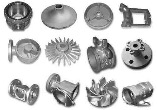
The core technical problem was unequivocal: how to create a sand mold that accurately defines the impeller’s external contours *and* its intricate internal blade passages, and then successfully remove the pattern or core boxes without destroying the fragile sand geometry. A conventional two-part mold was impossible because the undercut created by the enclosed front shroud and the blade curvature locks the pattern in place. After extensive experimentation, we devised and validated a strategy we term the “Open-Core, Closed-Mold” or “Split-Core, Monolithic-Casting” approach. This strategy deconstructs the problem by separating the molding of the internal blade-backplate assembly from the molding of the external shroud contour.
The process hinges on the creation of two primary tooling sets: the Blade-Backplate Core Box Assembly and the External Shroud Mold. The Blade-Backplate Core Box is a master pattern, typically machined from steel via CNC to achieve aerodynamic tolerances for blade profile (≤ 0.1 mm deviation) and blade exit angle (±0.5°). This assembly patterns the concave side of the blades and the entire backplate surface, including the hub. Critically, to solve the demolding issue, we introduced an innovative “Blade Stabilization Baseplate.” This component, with a clearance fit of less than 0.1 mm with the core box, supports the fragile sand during the crucial pattern withdrawal phase. The sequence involves placing this baseplate inside the core box, packing it with resin-bonded sand reinforced with a three-layer internal骨架 (chassis), and then carefully extracting the master steel pattern. The stabilizer plate holds the sand blades firmly in position, preventing collapse, drag, or scabbing. The resulting cured sand assembly is a precise, positive replica of the impeller’s internal passages—a complex core package that is itself a critical intermediary sand casting part in the process.
The external mold is comparatively straightforward. Using a separate pattern for the impeller’s outer silhouette (front shroud profile and outer diameter), a conventional two-part green sand mold (cope and drag) is prepared. The key assembly step then follows: the meticulously crafted internal sand core package is carefully lowered and positioned into the cavity of the external drag mold. The cope is then placed on top, completing the integrated mold assembly. This combination of a resin sand core and a green sand mold is a powerful hybrid approach for producing detailed sand casting parts. The complete mold ready for pouring now contains the precise negative space for the entire monolithic impeller.
| Component Name | Material / Type | Primary Function | Key Feature / Challenge Addressed |
|---|---|---|---|
| Blade-Backplate Core Box | CNC-machined Steel (Pattern) | To form the internal sand core defining blades and backplate. | High-precision aerodynamic surfaces. Must allow demolding of thin, curved blades. |
| Blade Stabilization Baseplate | Precision-machined Steel | To support sand blades during pattern withdrawal from core box. | ~0.1 mm clearance fit. Prevents core damage during demolding, enabling high yield. |
| Internal Sand Core | Resin-Bonded Sand (KJN-III binder) | Positive replica of impeller’s internal passages. Forms the casting’s interior geometry. | Reinforced with骨架. High dimensional stability and strength for handling. |
| External Shroud Pattern | Machined Metal or Plastic | To form the cope and drag mold defining the external contours. | Relatively simple geometry compared to the internal core. |
| Complete Mold Assembly | Hybrid (Resin Core + Green Sand Mold) | Integrated cavity for the final monolithic casting. | Combines precision of resin cores with economic & permeable green sand mold. |
The choice of sand and binder systems is critical for success. For the internal core, which must withstand handling and the metallostatic pressure of molten metal while preserving fine details, a cold-box resin sand system is ideal. We utilized a furan resin (KJN-III type) with a sulfuric acid ester catalyst. The core sand mixture’s strength can be modeled considering the binder bridge strength between sand grains. The tensile strength of the cured core $\sigma_c$ can be approximated as a function of binder properties and grain contact area:
$$ \sigma_c \propto \frac{A_b \cdot \sigma_b}{V_{total}} $$
where $A_b$ is the total cross-sectional area of binder bridges in the failure plane, $\sigma_b$ is the intrinsic tensile strength of the cured binder, and $V_{total}$ is the total volume under stress. Achieving a uniform distribution of high-strength binder bridges is paramount for cores defining thin sections like our 2 mm blades. For the external mold, a standard green sand mixture suffices, prioritizing permeability and collapsibility. A typical composition might be 80% reclaimed sand, 20% new silica sand (AFS 100/200), 5-6.5% moisture, and clay. Its properties are characterized by green compressive strength (e.g., 4.0 × 10⁴ Pa) and permeability number (>30).
With the mold assembled, the focus shifts to metallurgy and pouring. We selected ZL104 (A413.0 equivalent) aluminum alloy for its excellent castability, good strength, and corrosion resistance. The pouring temperature is tightly controlled between 760°C and 800°C. To ensure sound feeding and minimize defects in the thick hub section (which includes a cast-in steel sleeve for the shaft), a bottom-gating system is employed. This design ensures the hottest metal rises to feed the heavy section last, reducing shrinkage porosity. The steel sleeve is pre-heated to ~800°C, chemically cleaned, and features mechanical interlocks (grooves, knurls) to ensure perfect metallurgical and mechanical bonding within the aluminum sand casting part. The filling process is dynamic: initial fast pour to rapidly fill the thin blade sections and avoid mistruns, followed by a slower fill and possible supplementation to feed solidification shrinkage in the hub.
The solidification process is the final act of definition for the sand casting part. Understanding the thermal dynamics is key. The thin blades and shroud will solidify almost instantaneously upon contact with the sand, while the massive hub section will remain liquid much longer. Chills or controlled mold heating could be used to manipulate this gradient, but in our process, the thermal design of the mold and the gating suffice. The solidification time $t_s$ for a simple shape can be estimated using Chvorinov’s rule:
$$ t_s = B \cdot \left( \frac{V}{A} \right)^n $$
where $V$ is the volume of the casting section, $A$ is its surface area, $n$ is an exponent (often ~2), and $B$ is the mold constant dependent on mold material, metal properties, and superheat. For our impeller, the modulus $(V/A)$ is very small for the blades, leading to rapid solidification, and large for the hub, leading to prolonged solidification that must be fed.
| Parameter Category | Specification / Value | Rationale & Impact |
|---|---|---|
| Alloy | ZL104 (A413.0) | Excellent fluidity, good mechanical properties, suitable for complex thin-wall sand casting parts. |
| Pouring Temperature | 760 – 800 °C | Balances fluidity for filling thin sections with minimized gas pickup and shrinkage. |
| Mold Type (Core) | Cold-box Resin Sand | High strength & dimensional accuracy for intricate internal geometry. |
| Mold Type (External) | Green Sand (Clay-bonded) | Good permeability, cost-effective, and allows easy shakeout. |
| Gating System | Bottom Gating | Promotes directional solidification towards the heavy hub, aiding feeding. |
| Steel Sleeve Prep | Pre-heat to ~800°C | Prevents chilling of surrounding aluminum, ensures good bonding, reduces stress. |
Post-casting, the component undergoes standard foundry procedures: cooling, shakeout to remove the sand mold (the external green sand crumbles easily, while the internal resin core is mechanically removed), cutting of gates, and initial inspection. The cast impeller is then subjected to non-destructive testing (NDT), such as dye penetrant inspection, focusing on the blade roots and junction with the shroud—areas prone to potential shrinkage or hot tearing. Any minor imperfections are repaired using qualified welding procedures. Finally, the casting moves to machining: turning the outer diameter and front/rear faces, finish-boring the steel sleeve, and polishing the blade flow passages to achieve the desired surface finish (e.g., Ra 6.3). This transforms the raw sand casting part into a finished, precision component.
The effectiveness of this process is not merely theoretical. Implementation in batch production has yielded a consistent first-pass quality rate exceeding 78%. The monolithic construction delivers tangible benefits: significantly reduced vibration and noise compared to riveted counterparts due to better balance and damping, and superior structural integrity proven under rigorous environmental testing (vibration, shock, tilt). Furthermore, the tooling design allows for “one pattern, two orientations” use: by flipping the hub insert in the core box, both left-hand and right-hand rotation impellers can be produced from the same master tooling, enhancing flexibility and reducing tooling cost per piece for these specialized sand casting parts.
The principles established here extend far beyond this specific impeller geometry. The “Open-Core, Closed-Mold” philosophy is a powerful generic solution for a wide array of complex, enclosed castings. Components with internal grids, cooling channels, or multi-vane structures—common in pumps, turbines, compressors, and advanced heat exchangers—can be addressed with this methodology. The choice between using the sand core to define the internal passages (as we did) or the external features can be adapted based on the geometry. The process scalability is also noteworthy. While we focused on aluminum for its light weight and castability, the same sand molding principles apply to ductile iron, steel, copper alloys, and other metals, adjusting binder systems and pouring parameters accordingly. The fundamental challenge of molding an undercut, enclosed shape is solved by the strategic decomposition of the mold into manufacturable and demoldable sand components.
In conclusion, the development of this integrated sand casting process marks a significant advancement in the manufacture of highly complex, performance-critical components. By innovating at the mold-making stage—specifically through the “Open-Core” approach utilizing a stabilized resin sand core—we have successfully transitioned a traditionally fabricated multi-part assembly into a superior, monolithic sand casting part. This results in a component with enhanced dimensional accuracy, improved structural integrity, better dynamic performance, and ultimately, greater reliability. The process is robust, scalable, and broadly applicable, offering a viable and efficient pathway for the production of intricate enclosed geometries across various industries, solidifying the role of advanced sand casting as a vital technology for modern engineering.