
In the manufacturing industry, sand casting remains a pivotal method for producing complex metal components, especially for steel parts where cost-effectiveness and adaptability are paramount. As a researcher focused on enhancing the quality of sand casting parts, I have encountered numerous challenges related to defects such as porosity, inclusions, insufficient pouring, shrinkage cavities, and micro-shrinkage. These issues often lead to reduced qualification rates and increased production costs. To address this, I embarked on a study to optimize the sand casting process for a cast steel shell part using numerical simulation techniques. This approach allows for virtual experimentation, reducing trial-and-error cycles and providing insights into the effects of key parameters like pouring temperature and velocity. The goal is to minimize defects in sand casting parts and improve overall efficiency, which is crucial for applications in mining machinery, transportation, and heavy equipment.
Sand casting parts, particularly those made from steel, are widely used due to their superior mechanical properties and ability to withstand high loads. However, the process is prone to defects if not properly controlled. In this study, I focus on a ZG270-500 cast steel shell, which is a hollow component with intricate geometry and stringent internal surface requirements. The part has a mass of 392.93 kg and dimensions of 812 mm × 525 mm × 356 mm, with an average wall thickness of 8 mm. Such sand casting parts often exhibit localized thick sections that can lead to solidification-related defects. To optimize the process, I designed three different gating system schemes and employed ProCAST simulation software to analyze the filling and solidification behaviors. The primary variables investigated were pouring temperature and pouring velocity, as they significantly influence the formation of porosity and shrinkage in sand casting parts.
The chemical composition of the ZG270-500 steel used for the shell is critical for its performance. This medium-carbon steel offers a balance of strength, plasticity, and toughness, with a microstructure of austenite and ferrite. The composition is summarized in Table 1, which highlights the key elements that contribute to the material’s properties in sand casting parts.
| Element | Content (wt.%) |
|---|---|
| C | 0.4–0.5 |
| Mn | 0.7–0.8 |
| P | ≤ 0.04 |
| S | ≤ 0.05 |
| Fe | Balance |
In sand casting parts, the gating system design is essential to ensure smooth metal flow and minimize turbulence. Based on the parting plane selection principles, I initially devised two casting schemes. Scheme 1 involved placing the ingates at the base of the shell, while Scheme 2 positioned them at the cylindrical section. Both schemes utilized an open gating system to promote平稳 filling and reduce oxidation. For pouring, a bottom-pour ladle with a nozzle diameter of 40 mm was employed, with an average flow rate of 27 kg/s. The pouring time and rise velocity were calculated using fundamental formulas to validate the design. The pouring time \( t \) is given by:
$$ t = \frac{G_L}{N n q} $$
where \( G_L \) is the mass of molten steel in the mold (450 kg), \( N \) is the number of ladles (1), \( n \) is the number of nozzles per ladle (1), and \( q \) is the average pouring rate (27 kg/s). Substituting the values yields \( t = 16.7 \) s. The rise velocity \( v \) is then calculated as:
$$ v = \frac{C}{t} $$
where \( C \) is the height of the casting in the mold (356 mm). This results in \( v = 21.3 \) mm/s, which is within an acceptable range for sand casting parts to avoid defects. The gating system area ratios were set according to standard practices for steel castings: \( \sum A_{\text{choke}} : \sum A_{\text{sprue}} : \sum A_{\text{runner}} : \sum A_{\text{ingate}} = 1 : (1.8–2.0) : (1.8–2.0) : (2.0–2.5) \). With a nozzle diameter of 40 mm, the calculated areas were \( \sum A_{\text{choke}} = 1256 \, \text{mm}^2 \), \( \sum A_{\text{ingate}} = 2763 \, \text{mm}^2 \), and \( \sum A_{\text{sprue}} = 2386 \, \text{mm}^2 \) (corresponding to a sprue diameter of 55 mm).
Numerical simulation plays a crucial role in optimizing sand casting parts by predicting potential defects before physical production. I used ProCAST software to simulate the filling and solidification processes for each scheme. The pre-processing steps involved importing the 3D model of the shell and gating system, followed by mesh generation. The mesh size was set to 30 mm, resulting in 12,722 surface elements and 45,906 volume elements. After checking for issues like cracks and overlaps, I assigned material properties: the casting material was Medium-Carbon AISI 1040 (equivalent to ZG270-500), and the mold and cores were made of silica sand bonded with resin. The initial mold temperature was set to 25°C, with a heat transfer coefficient of 1000 W/(m²·K) at the metal-mold interface. Boundary conditions, gravity, and cooling methods were configured to replicate real-world conditions for sand casting parts.
The simulation results for Schemes 1 and 2 revealed significant defects. In Scheme 1, insufficient pouring occurred at the top of the cylindrical section, leading to incomplete filling. Similarly, Scheme 2 exhibited浇不足 defects in the same region. Moreover, both schemes showed substantial shrinkage porosity and cavities, with Scheme 1 having a porosity volume of 28.23 cm³ and Scheme 2 at 50.58 cm³. These defects rendered the sand casting parts unacceptable for use. The temperature fields indicated uneven cooling, with hotter spots in the thicker sections promoting shrinkage. To address these issues, I designed Scheme 3, which incorporated modifications to the gating system and added four open risers. Two risers had a diameter of 110 mm and height of 350 mm, while the other two were stepped with a lower diameter of 200 mm (height 32.5 mm) and upper diameter of 135 mm (height 330 mm). This design aimed to improve feeding and reduce defects in sand casting parts.
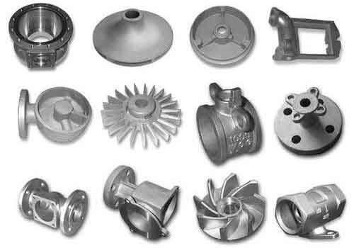
In sand casting parts, the filling process is critical for defect formation. For Scheme 3, the simulation showed that molten metal entered the mold cavity through the ingates, flowing downward and sideways before filling upward. This bottom-up filling helped vent gases and reduce air entrapment. The temperature distribution during filling indicated that the base regions cooled faster, while the cylindrical sections remained hotter, with temperatures dropping from an initial 1560°C to around 1100°C at the end of filling. The solidification process was slower, with the thin-walled base solidifying first and the thicker sections later, aided by the risers for补缩. The overall solidification time was longer than the filling time, but the optimized design minimized defects. The porosity volume in Scheme 3 was significantly reduced compared to the previous schemes, highlighting the importance of proper gating and riser placement in sand casting parts.
To further optimize Scheme 3, I conducted an orthogonal experiment to analyze the effects of pouring temperature and pouring velocity on porosity volume. These parameters are key factors in sand casting parts, as they influence fluidity, solidification rates, and defect formation. The factors and levels are presented in Table 2, with three levels for each factor to capture nonlinear effects.
| Level | Pouring Temperature (°C) | Pouring Velocity (m/s) |
|---|---|---|
| 1 | 1530 | 1.3 |
| 2 | 1560 | 1.6 |
| 3 | 1590 | 1.9 |
The orthogonal array comprised nine experimental runs, with porosity volume as the response variable. The results are summarized in Table 3, including the calculated K and R values for range analysis. The porosity volume was determined through ProCAST simulations for each combination, focusing on shrinkage cavities and micro-shrinkage in the sand casting parts.
| Run No. | Pouring Temperature (°C) | Pouring Velocity (m/s) | Porosity Volume (cm³) |
|---|---|---|---|
| 1 | 1530 | 1.3 | 2.368 |
| 2 | 1530 | 1.6 | 2.201 |
| 3 | 1530 | 1.9 | 2.503 |
| 4 | 1560 | 1.3 | 1.553 |
| 5 | 1560 | 1.6 | 1.416 |
| 6 | 1560 | 1.9 | 1.818 |
| 7 | 1590 | 1.3 | 1.984 |
| 8 | 1590 | 1.6 | 2.066 |
| 9 | 1590 | 1.9 | 2.206 |
In the range analysis, \( K_i \) represents the sum of porosity volumes for each level, and \( R \) is the range between the maximum and minimum \( K_i \) values. For pouring temperature, the \( K \) values were \( K_1 = 7.072 \), \( K_2 = 4.782 \), and \( K_3 = 6.256 \), giving \( R = 2.290 \). For pouring velocity, \( K_1 = 5.905 \), \( K_2 = 5.683 \), \( K_3 = 6.527 \), with \( R = 0.844 \). The larger \( R \) value for pouring temperature indicates it has a more significant influence on porosity volume in sand casting parts compared to pouring velocity. The optimal combination was determined as pouring temperature of 1560°C and pouring velocity of 1.6 m/s, which yielded the lowest porosity volume of 1.416 cm³. This aligns with the goal of minimizing defects in sand casting parts through parameter optimization.
The mechanism behind these results can be explained by the effects of temperature and velocity on molten metal behavior. Pouring temperature affects the fluidity and solidification time. Higher temperatures improve fluidity but can increase shrinkage due to greater thermal contraction, while lower temperatures may lead to premature solidification and insufficient filling. For sand casting parts, an optimal temperature balances these factors. Pouring velocity influences the turbulence and air entrapment; too high velocity can cause erosion and gas defects, whereas too low velocity may result in cold shuts. The orthogonal experiment revealed that a moderate velocity of 1.6 m/s combined with 1560°C provided the best outcome for reducing porosity in sand casting parts.
To validate the simulation findings, I considered practical implications for sand casting parts production. Using the optimized parameters from Scheme 3, the qualification rate of the cast steel shell increased from 81% to 96%, with a process yield of 66%. This demonstrates the efficacy of numerical simulation in enhancing the quality of sand casting parts. The microstructure and mechanical properties of the castings also met the required standards, confirming that the optimized process does not compromise material integrity. In sand casting parts, such improvements translate to reduced scrap, lower costs, and higher reliability in service.
Further analysis of the solidification process in sand casting parts can be supported by mathematical models. The solidification time \( t_s \) for a casting can be estimated using Chvorinov’s rule:
$$ t_s = k \left( \frac{V}{A} \right)^n $$
where \( V \) is the volume, \( A \) is the surface area, \( k \) is a constant dependent on mold material and casting conditions, and \( n \) is an exponent typically around 2. For sand casting parts, this rule helps identify hot spots prone to shrinkage. In Scheme 3, the risers were placed at locations with high \( V/A \) ratios to ensure directional solidification toward the feeders. Additionally, the heat transfer during solidification can be described by Fourier’s law, which governs thermal gradients critical for defect formation in sand casting parts.
The role of risers in sand casting parts is to compensate for volumetric shrinkage during solidification. The required riser volume \( V_r \) can be approximated as:
$$ V_r = \frac{V_c \cdot \beta}{\eta} $$
where \( V_c \) is the casting volume, \( \beta \) is the shrinkage rate (typically 4–6% for steel), and \( \eta \) is the riser efficiency. For the shell casting, with \( V_c \approx 0.05 \, \text{m}^3 \) and \( \beta = 0.05 \), assuming \( \eta = 0.2 \), \( V_r \approx 0.0125 \, \text{m}^3 \). The designed risers in Scheme 3 met this requirement, ensuring adequate补缩 for sand casting parts.
In terms of economic impact, optimizing sand casting parts through simulation reduces trial production cycles and material waste. Traditional methods rely on physical prototypes, which are time-consuming and expensive. Numerical simulation allows for rapid iteration of designs and parameters, leading to faster time-to-market. For industries relying on sand casting parts, such as automotive and machinery, this translates to significant cost savings and competitive advantage. Moreover, the environmental benefits include lower energy consumption and reduced scrap, aligning with sustainable manufacturing practices for sand casting parts.
The limitations of this study include the assumptions in simulation models, such as uniform mold properties and simplified boundary conditions. In actual sand casting parts production, factors like coating layers on mold surfaces can affect heat transfer and fluid flow. Future work could incorporate more detailed models for coatings and investigate residual stresses in sand casting parts. Additionally, the study focused on a specific steel alloy; exploring other materials for sand casting parts could broaden the applicability of the findings.
In conclusion, numerical simulation is a powerful tool for optimizing the sand casting process for steel shell parts. Through this study, I demonstrated that Scheme 3 with modified gating and riser design, combined with optimal pouring temperature and velocity, significantly reduces defects in sand casting parts. The orthogonal experiment highlighted pouring temperature as the dominant factor affecting porosity volume. The recommended parameters of 1560°C and 1.6 m/s resulted in a porosity volume of 1.416 cm³ and a qualification rate of 96%. These insights contribute to the advancement of sand casting technology, enabling the production of high-quality sand casting parts with improved efficiency and reduced costs. As the demand for reliable metal components grows, such optimization approaches will continue to play a crucial role in the foundry industry for sand casting parts.