
As a casting engineer with extensive experience in producing aluminum components, I have often encountered challenges in manufacturing large, complex sand casting parts. One notable project involved the development of a sand casting process for an aluminum fan used in locomotives. This fan, with a material specification of ZL101 aluminum alloy, presented significant difficulties due to its center-symmetric structure, large contour dimensions of approximately 1600 mm in diameter and 180 mm in height, and a weight of around 130 kg per piece. Initially, production using resin sand molds resulted in defects such as gas holes, inclusions, and shrinkage concavities, which compromised the integrity of these critical sand casting parts. Through systematic experimentation and analysis, I successfully refined the casting工艺 to achieve a 100% yield rate. In this article, I will share the detailed journey of optimizing the sand casting process for these aluminum fan parts, emphasizing the importance of gating system design, chill placement, and排气 considerations for high-quality sand casting parts.
The fan’s structure is inherently center-symmetric, featuring eight blades and eight rib plates arranged alternately around a central hub. This design leads to localized hot spots at the junctions where blade roots meet the hub and rib plates, as well as at the intersection of the hub and the fan’s web plate. These areas are critical for mechanical strength during operation, necessitating dense, defect-free microstructure in the final sand casting parts. To address this, the initial approach involved placing the web plate at the bottom using a吊芯 structure, with随型chills added at thick sections and risers positioned above blade roots for feeding. However, this setup proved insufficient, highlighting the complexities inherent in producing large sand casting parts.
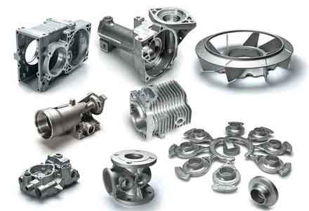
In sand casting, the selection of molding materials is crucial for achieving dimensional accuracy and surface finish in sand casting parts. For this project, resin sand was chosen due to its good collapsibility and ability to produce complex shapes. A胎模was created based on a physical sample, accounting for shrinkage allowances, and used to form a水泥随型底板 for consistency in molding these large sand casting parts. The gating system initially employed a top-pouring design with the sprue at the fan’s rotational center. This system included a pouring cup, straight sprue, horizontal runners, and ingates aligned parallel to the blades, connecting to the hub. Open risers were placed above each blade root to aid feeding. The rationale was to utilize the symmetry for uniform filling, but实践 revealed several issues.
The primary defects observed in the initial sand casting parts included severe gas holes and inclusions on the web plate surface, small slag eyes at blade roots, and shrinkage concavities on the outer sides of blade root chills. These defects are detrimental to the performance and longevity of sand casting parts, especially in dynamic applications like locomotive fans. Analysis indicated that the top-pouring system caused turbulent metal flow, leading to excessive oxidation and slag entrapment. The aluminum melt entered the mold cavity from the hub, resulting in splashing and dispersed flow that increased oxidation surface area. This generated大量氧化夹渣, which accumulated on the web plate. Additionally,排气 was inadequate: gases in the web plate cavity had to escape upward and downward, but the bottom was blocked by a solid chill, and the top was surrounded by the gating system and cavity, trapping gas and forming holes. Slag eyes at blade roots occurred because slag particles上升to the risers were counteracted by incoming metal flow from the ingates, causing旋转and trapping at chill surfaces. Shrinkage concavities arose due to excessive chilling at blade roots, which prematurely solidified feeding channels, preventing adequate补缩to outer blade sections.
To overcome these challenges, I redesigned the工艺 with a focus on stabilizing metal flow, enhancing排气, and optimizing chill effectiveness for these sand casting parts. The key modification was switching from a top-pouring to a bottom-pouring gating system, while maintaining riser locations. The sprue was introduced at the fan’s rotational center through a core assembly, with runners formed between cores and ingates positioned near the center of the web plate. This半封闭式system promoted laminar flow, reducing oxidation and slag formation. The chill design was also revised: the large single chill under the web plate was replaced with six smaller chills drilled with排气 holes to facilitate gas escape. At blade roots, the upper chills were removed, retaining only the lower ones to moderate chilling and maintain feeding paths. These adjustments were critical for improving the quality of sand casting parts.
The effectiveness of these changes can be quantified through various casting parameters. For instance, the filling time \( t_f \) for a sand casting part can be estimated using the equation:
$$ t_f = \frac{V}{Q} $$
where \( V \) is the volume of the mold cavity and \( Q \) is the volumetric flow rate of the aluminum melt. In the original top-pouring system, \( Q \) was highly variable due to turbulence, leading to prolonged \( t_f \) and increased oxidation. The bottom-pouring system stabilized \( Q \), reducing \( t_f \) and minimizing exposure. Additionally, the thermal dynamics at hot spots can be modeled using the Chvorinov’s rule for solidification time \( t_s \):
$$ t_s = k \left( \frac{V}{A} \right)^2 $$
where \( k \) is a mold constant, \( V \) is the volume of the section, and \( A \) is its surface area. For thick sections like blade roots, \( t_s \) is longer, necessitating chills to accelerate cooling. The revised chill design balanced this by adjusting the chill面积 \( A_c \) to control the heat extraction rate \( \dot{Q}_c \):
$$ \dot{Q}_c = h \cdot A_c \cdot (T_m – T_c) $$
where \( h \) is the heat transfer coefficient, \( T_m \) is the melt temperature, and \( T_c \) is the chill temperature. By reducing \( A_c \) at blade roots and adding排气 holes in web chills, both cooling and gas venting were optimized for these sand casting parts.
To summarize the工艺 parameters before and after optimization, I have compiled the following tables. These data highlight the critical factors influencing the quality of sand casting parts.
| Parameter | Value | Description |
|---|---|---|
| Material | ZL101 Al-Alloy | Common casting alloy with good fluidity and mechanical properties |
| Contour Dimensions | Ø1600 mm × 180 mm | Large, center-symmetric structure |
| Weight | ~130 kg | Substantial mass requiring careful feeding |
| Structure | 8 blades, 8 rib plates, hub, web | Multiple hot spots at junctions |
| Casting Method | Resin Sand Mold | Used for flexibility and detail in sand casting parts |
| Aspect | Original Design (Top-Pouring) | Improved Design (Bottom-Pouring) |
|---|---|---|
| Sprue Location | At rotational center, top | At rotational center, through core |
| Ingate Position | At hub, parallel to blades | Near web plate center |
| Flow Character | Turbulent, dispersed | Laminar, directional |
| Oxidation Risk | High due to splashing | Reduced due to stable flow |
| Slag Entrapment | Likely at web and blade roots | Minimized through controlled filling |
| 排气 Alignment | Poor; gases trapped | Good; gases escape with flow |
| Location | Original Chill Design | Improved Chill Design | Impact on Sand Casting Parts |
|---|---|---|---|
| Web Plate Bottom | One large solid chill | Six small chills with排气 holes | Enhanced gas escape; reduced thermal stress |
| Blade Roots | Upper and lower chills | Lower chill only | Balanced cooling; prevented shrinkage concavities |
| Rib Plate Junctions | Chills at intersections | Retained with optimized size | Controlled hot spot solidification |
| Preheating Temperature | Not specified | 100 ± 10 °C | Reduced thermal shock in molds for sand casting parts |
The improved工艺 was implemented with additional considerations to further enhance the reliability of sand casting parts. Riser were kept as open type to aid排气 and increase filling pressure. Multiple排气 holes were pre-set in the cores and mold to ensure gas evacuation. Before mold assembly, chills were preheated to 100 ± 10 °C to avoid rapid cooling and potential cracking in the sand casting parts. Pouring temperature was lowered to 720 ± 10 °C to reduce shrinkage and gas solubility. During pouring, a large initial flow was used to fill the pouring cup quickly, followed by a slower rate to facilitate slag skimming—a practice essential for clean sand casting parts.
The results were显著: over 30 fan castings were produced without any of the previous defects, achieving a 100% yield rate. Surface quality also improved, demonstrating that the optimization effectively addressed the core issues. This success underscores the importance of tailoring the sand casting process to the specific geometry of sand casting parts. For center-symmetric components like this fan, introducing the gating system from the rotational center ensures uniform filling. Moreover, aligning排气 directions with metal flow paths is crucial to prevent gas entrapment. Chill design must account for both cooling efficiency and gas permeability, as seen in the use of drilled chills. These principles are broadly applicable to other large, complex sand casting parts.
To delve deeper into the science behind these improvements, let’s consider some mathematical models that govern sand casting processes. The flow of aluminum melt in gating systems can be described by Bernoulli’s equation for incompressible fluids:
$$ P + \frac{1}{2} \rho v^2 + \rho g h = \text{constant} $$
where \( P \) is pressure, \( \rho \) is density, \( v \) is velocity, \( g \) is gravity, and \( h \) is height. In the original top-pouring system, high \( v \) at the sprue exit caused turbulence, whereas the bottom-pouring system reduced \( v \) by spreading flow through runners, minimizing kinetic energy losses and oxidation. For slag removal, Stokes’ law can be applied to estimate the上升 velocity \( u_s \) of slag particles:
$$ u_s = \frac{2 g r^2 (\rho_p – \rho_m)}{9 \eta} $$
where \( r \) is particle radius, \( \rho_p \) is slag density, \( \rho_m \) is melt density, and \( \eta \) is dynamic viscosity. By stabilizing flow, the improved system allowed slag particles to rise smoothly to risers without interference, reducing inclusions in sand casting parts.
Furthermore, the solidification feeding requirements for sand casting parts can be assessed using the modulus method. The modulus \( M \) of a section is defined as:
$$ M = \frac{V}{A} $$
Sections with higher \( M \) solidify slower and require feeding. For the fan, blade roots and web-hub junctions had high \( M \), necessitating risers and chills. The revised chill layout adjusted the effective modulus \( M_{\text{eff}} \) by increasing surface area through segmentation, thereby accelerating solidification and reducing shrinkage defects in these sand casting parts.
| Parameter | Optimal Range | Rationale |
|---|---|---|
| Pouring Temperature | 720 ± 10 °C | Balances fluidity and shrinkage for aluminum sand casting parts |
| Chill Preheating | 100 ± 10 °C | Prevents thermal shock and improves metal-chill contact |
| Gating System Type | Bottom-pouring, semi-closed | Ensures laminar flow and reduces oxidation in sand casting parts |
| 排气 Hole Diameter | 3-5 mm (in chills) | Allows gas escape without metal penetration |
| Riser Size | Based on modulus calculations | Provides adequate feeding for thick sections in sand casting parts |
| Mold Material | Resin sand | Offers good collapsibility and detail for complex sand casting parts |
In practice, the production of sand casting parts involves iterative testing to fine-tune these parameters. For this fan, several trial casts were conducted to validate the改进工艺. Data from these trials can be analyzed statistically to ensure consistency. For example, the defect rate \( D \) as a function of pouring temperature \( T_p \) and chill preheating \( T_c \) can be modeled empirically:
$$ D = \alpha (T_p – T_{p0})^2 + \beta (T_c – T_{c0})^2 + \gamma $$
where \( \alpha, \beta, \gamma \) are constants determined from experiments, and \( T_{p0}, T_{c0} \) are optimal temperatures. By minimizing \( D \), we achieve robust process windows for sand casting parts. In this case, the optimal conditions were as noted earlier, leading to defect-free sand casting parts.
Beyond this specific application, the lessons learned are valuable for a wide range of sand casting parts. Center-symmetric geometries, common in wheels, gears, and impellers, benefit from radial gating systems that promote even filling. The integration of排气 features into chills is a novel approach that can be adopted for other thick-walled sand casting parts where gas entrapment is a concern. Additionally, the use of modular chills—small, reusable pieces—enhances flexibility and reduces costs in sand casting production. These strategies contribute to the overall goal of producing high-integrity sand casting parts for demanding applications.
In conclusion, the optimization of the sand casting process for aluminum fan parts demonstrates the critical interplay between gating design, chill placement, and排气 management. By switching to a bottom-pouring system, revising chill configurations, and ensuring proper venting, I eliminated defects and achieved consistent quality in these large sand casting parts. The key takeaways are: first, for center-symmetric sand casting parts, the gating system should be introduced from the rotational center to ensure uniform filling; second,排气 directions must align with metal flow to prevent gas holes; third, chills should be designed to balance cooling with gas escape, avoiding over-chilling that leads to shrinkage issues. These principles, supported by mathematical models and empirical data, provide a framework for improving the manufacture of complex sand casting parts. As casting technologies evolve, such insights will continue to enhance the reliability and performance of sand casting parts across industries.
To further illustrate the importance of these factors, consider the general equation for casting yield \( Y \) in sand casting parts production:
$$ Y = \frac{W_{\text{casting}}}{W_{\text{total}}} \times 100\% $$
where \( W_{\text{casting}} \) is the weight of the usable casting and \( W_{\text{total}} \) is the total weight of metal poured. In the original process, low yield due to defects reduced efficiency, whereas the improved process maximized \( Y \) by minimizing scrap. This economic aspect is vital for the sustainable production of sand casting parts. Additionally, the mechanical properties of sand casting parts, such as tensile strength \( \sigma_t \) and elongation \( \epsilon \), can be correlated with process parameters via equations like:
$$ \sigma_t = \sigma_0 + k_1 \cdot \Delta T + k_2 \cdot t_s $$
where \( \sigma_0 \) is a base strength, \( \Delta T \) is undercooling, and \( k_1, k_2 \) are constants. By optimizing cooling rates through chills, we enhance the microstructure and performance of sand casting parts.
In summary, the successful refinement of this sand casting process underscores the value of a systematic, analytical approach in foundry practice. Whether for locomotive fans or other components, attention to detail in gating, chilling, and venting can transform challenging sand casting parts into reliable products. I hope this detailed account provides useful insights for engineers and practitioners working on similar sand casting projects.