
This document details a comprehensive investigation and process development initiative undertaken to successfully produce a complex, high-integrity aluminum alloy housing via sand casting. The component in question is a critical coupling shell for a hydraulic torque converter, a key part of the transmission system in mining conveyor belts. These sand casting parts operate under severe conditions and are subject to frequent failure, necessitating reliable and economical reproduction for repair purposes. The primary challenge was to achieve the required metallurgical soundness to withstand a post-machining hydrostatic pressure test of 8 atmospheres without leakage, a performance level traditionally associated with more expensive permanent mold or low-pressure casting processes for such components.
The initial production attempts using conventional green sand casting techniques consistently resulted in rejection. After machining, the castings would fail the pressure test, exhibiting leakage primarily from several isolated, thickened sections—or hot spots—within the structure. These areas, corresponding to future drill sites for oil passages, pressure relief valves, and balancing pads, as well as internal fillets, are inherent to the part’s design. The geometry of these sand casting parts creates natural thermal centers that solidify last, making them highly susceptible to shrinkage porosity in a slow-cooling sand mold. This porosity manifests as interconnected micro-channels, leading to leakage under pressure.
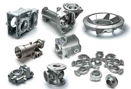
The core scientific problem revolves around solidification control in sand molds. The sequential freezing of a casting dictates its soundness. Areas that solidify last require a feed of liquid metal to compensate for the volumetric shrinkage associated with the liquid-to-solid phase change (approximately 6-7% for many Al alloys). If this feed path is interrupted or the isolated hot spot has no feeding source, shrinkage porosity forms. The governing relationship for solidification time, according to Chvorinov’s Rule, is:
$$ t = B \left( \frac{V}{A} \right)^n $$
where \( t \) is the solidification time, \( V \) is the volume of the casting section, \( A \) is its surface area, \( n \) is an exponent typically around 2, and \( B \) is a mold constant. For sand molds, \( B \) is relatively large, leading to longer solidification times and broader mushy zones compared to metal molds. This exacerbates feeding difficulties and promotes dendritic growth that can block interdendritic feeding, leading to micro-porosity. The problem in these specific sand casting parts was that the critical hot spots had high \( V/A \) ratios and were thermally isolated, making \( t \) for these zones significantly longer than for the surrounding walls.
The initial process setup is summarized below. While logically sound for moldability, it lacked the specific controls needed to ensure soundness at the critical locations.
| Process Parameter | Initial Configuration |
|---|---|
| Parting Line & Pouring Position | Horizontal split through the part’s central axis. |
| Gating System | Central downsprue with four radial ingates at the base. |
| Feeding Strategy | No dedicated risers; gating system acted primarily as a filling conduit. |
| Cooling Aids | None employed. |
| Thermal Modifications | None. |
The systematic solution was built on three interconnected pillars: 1) Accelerating solidification at hot spots, 2) Enhancing feeding where possible, and 3) Redesigning geometry to minimize thermal mass. A multi-faceted experimental approach was designed and implemented.
1. Enhanced Feeding via the Gating System
The central gating system was reconceptualized from a mere filling channel into a functional feeding riser. The cross-sectional areas of the sprue and ingates were substantially increased. This modification served a dual purpose: it promoted the flow of hotter metal into the mold cavity during filling (favorable thermal gradient), and more importantly, it provided a large reservoir of liquid metal that remained molten longer than the central hub of the casting (Hot Spot A). According to the feeding distance concepts, effective feeding requires a gradient where \( T_{riser} > T_{casting} \) and that the riser solidifies last. The enlarged gating system was designed to meet these criteria for the central region. The design change is quantified below:
| Gating Element | Initial Diameter/Area | Modified Diameter/Area | Function |
|---|---|---|---|
| Downsprue | Small | Significantly Enlarged | Provides feeding metal volume. |
| Ingates (each) | Small cross-section | Enlarged cross-section | Maintains open feeding path longer. |
2. Application of Chills for Localized Solidification Control
To address the isolated hot spots (B, C, D) which could not be fed by a riser, the strategic use of chills was implemented. Chills are materials of high thermal conductivity (like steel) placed in the mold to extract heat rapidly from specific areas, effectively reducing the local solidification time \( t \) by altering the effective mold constant \( B \) in that region.
- Internal Chills (for Hot Spots B & C): Steel (for C) and aluminum (for B) rods were placed within the mold cavity at the locations of future drilled holes. These become part of the final casting and are later machined out. They act as massive heat sinks, initiating rapid solidification from the inside of the hot spot. The effectiveness of an internal chill can be modeled by considering the heat balance between the molten metal and the chill mass. The chill’s ability to absorb heat \( Q \) is given by:
$$ Q = m_{chill} \cdot c_{chill} \cdot \Delta T_{chill} + m_{chill} \cdot L_{f,chill} $$
(if the chill melts partially). By rapidly absorbing heat, they promote directional solidification towards themselves, reducing the size of the mushy zone and encouraging more planar growth, which minimizes porosity. - External Chills (for Hot Spot A – tested): A thick steel external chill was also trialed on the outer surface of the central hub. However, its effectiveness was found to be limited due to direct impingement and heating by the incoming metal stream, which raised its initial temperature and diminished its chilling power. This observation underscores the importance of chill placement relative to fluid flow dynamics in the mold.
3. Geometrical Modification for Improved Castability
For Hot Spot D, which was a deliberately thickened pad for balancing, the most effective solution was to reduce its thermal mass within the constraints of its functional requirement. By slightly tapering or reducing its cross-sectional thickness, its \( V/A \) ratio was decreased, bringing its solidification time closer to that of the adjoining walls. This simple redesign eliminated the thermal isolation and made the area less prone to shrinkage. This principle is fundamental to designing castings, especially for sand casting parts where heat extraction is slow: uniform wall thickness is paramount.
4. Complementary Process Optimizations
To support the primary mechanical interventions, key foundry process parameters were tightened:
- Melt Treatment: Rigorous degassing (e.g., using rotary inert gas injection) was employed to minimize dissolved hydrogen content. Hydrogen precipitation during solidification can significantly enlarge any micro-porosity formed by shrinkage. The reduced gas content helps keep pores small and isolated, improving pressure tightness.
- Pouring Temperature: The pouring temperature was carefully lowered to near the alloy’s liquidus point, while ensuring complete mold filling. This reduces the total liquid contraction volume \( \Delta V_{liq} \) that must be fed and decreases the temperature gradient, promoting more simultaneous solidification which can be beneficial when combined with chilling. The superheat \( \Delta T \) is a critical control variable:
$$ \Delta T = T_{pour} – T_{liquidus} $$
A lower \( \Delta T \) was targeted.
The consolidated strategy for producing these high-integrity sand casting parts is summarized in the following table, contrasting the initial and final optimized approaches for each hot spot.
| Hot Spot / Zone | Initial Problem & Solution | Optimized Strategy | Governing Principle |
|---|---|---|---|
| A (Central Hub) | Microporosity from insufficient feeding. | Enlarge gating system to act as a feeding riser. External chill found ineffective. | Extend effective feeding distance; ensure thermal gradient towards riser. |
| B & C (Future Drill Sites) | Isolated thermal centers causing shrinkage. | Placement of internal chills (steel/Al). Chill is later machined out. | Force directional solidification via internal heat sink; drastically reduce local solidification time \( t \). |
| D (Balancing Pad) | Thick section solidifying last. | Redesign to reduce section thickness where functionally allowable. | Minimize \( V/A \) ratio to promote uniform cooling. |
| Overall Process | Conventional sand practice. | Strict melt degassing and controlled low pouring temperature. | Minimize shrinkage and gas porosity synergies. |
Theoretical Analysis and Results
The success of the modified process can be analyzed through solidification modeling. The key was to manipulate the temperature field \( T(x,y,z,t) \) within the mold. The heat transfer is governed by the Fourier equation:
$$ \frac{\partial T}{\partial t} = \alpha \left( \frac{\partial^2 T}{\partial x^2} + \frac{\partial^2 T}{\partial y^2} + \frac{\partial^2 T}{\partial z^2} \right) $$
where \( \alpha \) is the thermal diffusivity. The chills effectively introduced a boundary condition of very high heat flux at specific locations, creating steep thermal gradients \( \nabla T \) away from the chill surface. This gradient is the driving force for directional solidification.
For the internal chills, the solidification front velocity \( v \) at the chill/metal interface is initially very high, promoting a stable planar interface and dense structure. The Niyama criterion, often used to predict shrinkage porosity, relates the local thermal gradient \( G \) and the solidification rate \( R \):
$$ Niyama = \frac{G}{\sqrt{R}} $$
A higher Niyama value indicates a lower risk of shrinkage. The chills act to significantly increase \( G \) in their vicinity, thereby raising the Niyama value and improving soundness for these critical sand casting parts.
The experimental batches produced with the integrated optimized process yielded definitive results. Initial trials with only enlarged gating (and ineffective external chills) still showed leakage, proving that feeding alone was insufficient for the most isolated hot spots. However, subsequent batches incorporating internal chills and the geometric modification achieved 100% success in the 8-atmosphere hydrostatic test. The pressurized water equation:
$$ P = \rho g h $$
where \( P \) is the pressure (80 m of water column head), \( \rho \) is density, and \( g \) is gravity, represents a stringent test for the interconnectedness of any porosity. The fact that the castings withstood this pressure confirmed the discontinuity and minimal size of any remaining micro-porosity.
| Batch | Key Modifications Applied | Hydrostatic Test Result (8 atm) | Conclusion |
|---|---|---|---|
| Initial Production | None (baseline process). | Failed – Leakage at multiple hot spots. | Conventional sand casting insufficient. |
| Trial 1 | Enlarged gating only (+ external chill on A). | Failed – Leakage at B, C, D. | Feeding helps A, but isolated hot spots remain problematic. |
| Trial 2 & 3 | Full suite: Enlarged gating + Internal chills (B,C) + Geometry mod (D) + Process controls. | Passed – No leakage observed. | Integrated approach achieves required soundness for sand casting parts. |
Conclusion and Broader Implications
This study conclusively demonstrates that through a scientifically-guided, integrated approach, sand casting is fully capable of producing high-integrity, pressure-tight aluminum alloy components that must withstand significant service loads. The limitations of the process related to slow cooling and shrinkage formation can be systematically overcome by:
- Designing the gating system for feeding, not just filling.
- Employing strategic chilling (particularly internal chills) to radically alter the solidification sequence at isolated hot spots.
- Collaborating on part design to improve castability through uniform wall sections.
- Implementing rigorous process controls for melt quality and pouring temperature.
The success hinges on understanding and manipulating the fundamental principles of heat transfer and solidification. This case study provides a validated methodological framework for producing other complex, high-performance sand casting parts where the economics of permanent tooling are not justified. It elevates sand casting from a process for simple shapes to a viable option for critical components, expanding its application potential in repair, low-volume, and high-mix manufacturing scenarios. The ability to produce such sound sand casting parts reliably offers a significant economic advantage, preserving the inherent flexibility of sand molds while meeting stringent mechanical property requirements.