
As an engineer deeply involved in foundry operations, I view sand casting as a fundamental and versatile metal forming process. The principle involves pouring molten metal into a mold cavity formed in sand, allowing it to solidify, and subsequently extracting a part of the desired shape. This method remains the most widely used casting process globally. The sand casting industry is a cornerstone of modern manufacturing, and its technological level is a significant indicator of a nation’s industrial capability. Its status is irreplaceable in both developing and developed economies.
Within the manufacturing ecosystem, the automotive industry stands as the largest consumer of sand casting parts. It serves as the primary driving force behind innovations and demands in the foundry sector. In an average automobile, castings account for approximately 20% of the total vehicle weight, making them the second most used material after various forms of steel. The heart of the automobile, the engine, dictates the vehicle’s overall performance and longevity. Critically, key engine components such as cylinder blocks, cylinder heads, intake and exhaust manifolds, crankshafts, and exhaust pipes are predominantly manufactured as sand casting parts. Therefore, the evolution of the automotive industry, with its continuous demands for lighter, stronger, and more complex components, directly shapes the future of sand casting. This symbiotic relationship underscores the immense importance of casting process design for automotive components.
This discussion focuses on the process design for a specific automotive component: a turbocharger rear exhaust pipe. This part functions as the connecting pipe between the turbocharger and the muffler. During operation, it must withstand the hot, pulsating exhaust gases expelled from the engine cylinders. Consequently, it demands high resistance to thermal fatigue (heat checking), wear, thermal shock, and must maintain excellent gas tightness. This particular sand casting part is traditionally produced using green sand molding techniques.
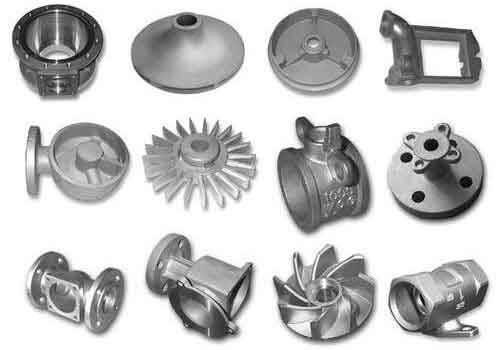
Fundamentals of Sand Casting
Sand casting utilizes a refractory aggregate (sand) bonded with a binder to create a mold. The molten metal fills this mold under gravitational force. The mold is typically an assembly of a cope and drag, often incorporating separate sand cores to define internal features. The two most basic raw materials are foundry sand (usually silica-based) and a binding agent. The advantages of sand casting are numerous: the molding materials are inexpensive and readily available, mold production is relatively straightforward, and the process offers exceptional flexibility, suitable for both low-volume jobbing and high-volume mass production. It is the most traditional yet adaptable casting method, renowned for its cost-effectiveness and short lead times. The generalized process flow is as follows: Pattern Making -> Core Making -> Molding -> Mold Assembly -> Melting & Pouring -> Cooling -> Shakeout -> Cleaning & Finishing -> Inspection.
Process Design for a Turbocharger Exhaust Pipe Sand Casting
The quality of sand casting parts is profoundly influenced by the design of the gating system, risers, and the application of chills. A systematic design approach is crucial to prevent defects.
Gating System Design
The cross-sectional areas of the gating channels are critical. An undersized system leads to prolonged filling time, risking defects like cold shuts and mistruns. An oversized system causes excessively high flow velocities, leading to mold erosion (washing) and dross entrainment. Therefore, determining the optimal gating dimensions is essential for controlled mold filling.
1. Selection of Gating System Type:
For the thin-walled, complex structure of the exhaust pipe, a partially pressurized (or choke-controlled) gating system with a side gate (middle injection) is preferable. This design offers a slower initial filling velocity compared to a fully pressurized system, provides some slag-trapping capability in the runner, and ensures relatively tranquil mold filling, making it widely suitable for small gray iron castings.
2. Design and Calculation of the Gating System:
The pouring time, representing the filling speed, is paramount. An optimal time exists for any casting. For gray iron sand casting parts weighing less than 450 kg and with complex, thin walls, the pouring time (t) can be estimated using an empirical formula:
$$ t = S_1 \sqrt{G_L} $$
Where:
• \( t \) = Pouring time (seconds)
• \( G_L \) = Total poured weight, including castings and gating/risers (kg)
• \( S_1 \) = Coefficient dependent on casting wall thickness
The value of \( S_1 \) is selected from the following table based on the dominant wall thickness of the sand casting parts:
| Casting Wall Thickness (mm) | 2.5 – 3.5 | 3.5 – 8.0 | 8.0 – 15 |
|---|---|---|---|
| Coefficient \( S_1 \) | 1.63 | 1.85 | 2.2 |
For our exhaust pipe with a wall thickness of ~5mm, \( S_1 = 1.63 \). Assuming \( G_L = 6.5 \) kg, the calculated pouring time is:
$$ t = 1.63 \times \sqrt{6.5} \approx 4.2 \text{ seconds} $$
Determination of Average Static Pressure Head (\(H_p\)):
For a side-gated system (middle injection), the effective metal pressure head is calculated as:
$$ H_p = H_0 – \frac{h_c}{8} $$
Where:
• \( H_0 \) = Height from the pouring cup top to the parting line (620 mm)
• \( h_c \) = Total height of the casting in the mold (336 mm)
Thus:
$$ H_p = 620 – \frac{336}{8} = 620 – 42 = 578 \text{ mm} $$
Calculation of Minimum Ingate Area (\(A_g\)):
The minimum required cross-sectional area for the ingate(s) for gray iron sand casting parts is given by:
$$ A_g = \frac{G_L}{0.31 \mu t \sqrt{H_p}} $$
Where \( \mu \) is the friction factor (loss coefficient) of the gating system. Typical values for iron castings are:
| Mold Type | High Resistance | Medium Resistance | Low Resistance |
|---|---|---|---|
| Green Sand | 0.35 | 0.42 | 0.50 |
| Dry Sand | 0.41 | 0.48 | 0.60 |
Selecting \( \mu = 0.42 \) for a green sand mold with medium resistance, we calculate \(A_g\):
$$ A_g = \frac{6.5}{0.31 \times 0.42 \times 4.2 \times \sqrt{578}} \approx \frac{6.5}{0.31 \times 0.42 \times 4.2 \times 24.04} \approx \frac{6.5}{13.15} \approx 0.494 \text{ cm}^2 = 49.4 \text{ mm}^2 $$
This is the theoretical minimum. For a partially pressurized system in small castings, common area ratios are used:
• Sprue base / Runner / Ingate ratio ≈ 1.15 : 1.4 : 1.0
Therefore, scaling up:
$$ A_g(\text{design}) = 49.4 \times (1.15 \approx 1.4?) \text{ Let’s define clearly:} $$
For a robust system, a larger \(A_g\) is often chosen. If we design based on a chosen \(A_g\) of 156 mm² for instance, then:
$$ A_{\text{sprue}} = 1.15 \times A_g = 1.15 \times 156 = 179.4 \text{ mm}^2 $$
$$ A_{\text{runner}} = 1.4 \times A_g = 1.4 \times 156 = 218.4 \text{ mm}^2 $$
Based on the actual geometry of the exhaust pipe sand casting part, final dimensions might be adjusted to: Ingate = 178 mm², Runner = 375 mm², Sprue = 314 mm² to ensure proper flow and feeding.
Riser and Chill Design
Defects like leakage (from shrinkage porosity) and fracture (from mistruns and macro-shrinkage) in sand casting parts are often mitigated by strategic use of risers and chills.
1. Riser Design:
A riser is a reservoir of molten metal that feeds the casting during solidification to compensate for volumetric shrinkage. Its design aims to solidify after the casting section it feeds. For gray iron sand casting parts, which experience graphitic expansion, risers are primarily used for feeding heavy sections or isolated thermal centers. The riser should be placed at the hottest spot, typically the thickest section or the top of the casting. A cylindrical riser shape is often chosen for its favorable surface-area-to-volume ratio, which delays solidification. For this pipe fitting, risers are positioned on the top flange areas. The feeding distance for gray iron is approximately 10 to 17 times the section thickness. For a 5mm wall, a feeding distance of 50mm is appropriate.
2. Chill Design:
Chills are metal inserts placed in the mold to locally increase the cooling rate. They help establish directional solidification towards a riser or simply accelerate cooling in an isolated hot spot to prevent shrinkage porosity. For the exhaust pipe, simulation or empirical data indicated a risk of shrinkage at the lower pipe bend. Placing external chills in that region of the mold helps promote faster solidification, eliminating the isolated thermal center and preventing the defect in the final sand casting parts.
Core Design
The production of hollow sand casting parts like pipes necessitates the use of cores. Cores are pre-formed sand shapes inserted into the mold to create internal cavities. The exhaust pipe’s internal passage is entirely formed by a core.
1. Core Sand Material Selection:
Cores must possess higher strength than the main mold sand because they are often surrounded by molten metal and have limited support points. They require good collapsibility after casting to allow for removal. In modern practice, resin-bonded sands are dominant for core-making. Among them, coated sand (or “shell sand”) is exceptionally popular. It consists of sand grains pre-coated with a phenolic resin. This material flows freely at room temperature, offers excellent dimensional accuracy, high strength, and good breakdown properties. Its widespread use in automotive castings—for engine blocks, heads, and manifold cores—makes it the ideal choice for producing the complex cores required for exhaust pipe sand casting parts.
2. Core Making Process:
The standard equipment for producing cores from coated sand is a shell core shooting machine. The process is highly automated:
1. The sand magazine opens, filling the shooting chamber with resin-coated sand.
2. The magazine closes, sealing the chamber.
3. A core box, heated to around 250-300°C, is clamped in position.
4. The shooting head presses against the core box.
5. Compressed air propels the sand into the heated cavity.
6. The heat melts the resin on the sand grains in contact with the hot core box, forming a rigid shell of a specific thickness.
7. After a dwell time, the excess sand is dumped back (inverted), leaving the hollow shell core.
8. The core undergoes further curing in the hot box before being ejected.
A well-made core for sand casting parts will have a uniform brownish-yellow color on the surface, indicating proper curing. Under-cured cores appear pale yellow or white, while over-cured cores turn dark brown or black. The core must be geometrically accurate, with smooth surfaces to ensure the quality of the cast internal passage.
Validation and Summary
The designed sand casting process—encompassing the gating, risering, chilling, and core-making—must be validated. Today, this is efficiently done using casting simulation software. Numerical modeling allows us to visualize the fill pattern, track solidification progression, and predict the location of potential defects like shrinkage porosity or cold shuts before any metal is poured. For the turbocharger exhaust pipe, simulation would typically reveal areas at risk in the initial design. The iterative process involves modifying riser placement and size, adjusting chill locations, and potentially tweaking the gating until the simulation shows a sound casting free of major defects in the part itself. It is acceptable for minor shrinkage to be transferred into the gating system or risers, as these are removed during cleaning.
In summary, the production of high-integrity sand casting parts for demanding automotive applications like exhaust components requires a meticulous, science-driven approach to process design. By carefully calculating gating dimensions based on fluid flow and thermal principles, strategically implementing risers and chills to control solidification, and selecting advanced core-making technologies for dimensional fidelity, foundries can consistently produce qualified castings. The sand casting process, with its enduring flexibility and continuous technological evolution, remains perfectly capable of meeting the stringent quality challenges presented by modern automotive sand casting parts. The successful production of a leak-proof, durable turbocharger exhaust pipe validates the effectiveness of this comprehensive design methodology.