
The manufacturing of molds for sand casting parts presents a distinct set of challenges that differ significantly from those encountered in injection or die-casting mold production. While the latter prioritize high precision and mass production for net-shape components, sand casting molds are designed to produce rough castings—the sand casting parts—which subsequently undergo machining to achieve final dimensional and surface finish requirements. The core objective shifts from final product geometry to creating a mold that faithfully incorporates all necessary allowances for shrinkage, machining stock, draft angles, and fillets essential for the casting process itself. This fundamental difference dictates a unique approach to Computer-Aided Manufacturing (CAM) programming and process planning. In this detailed account, I will share the comprehensive optimization strategy developed for the CNC machining of a complex timing gear chamber sand casting mold, focusing on how systematic path planning and parameter selection drastically improved efficiency and tool life.
The journey begins with the digital definition of the sand casting part. Using 3D CAD software, the rough casting model is constructed based on the finished product drawing, meticulously adding all required machining allowances and draft. For the timing gear chamber, this resulted in a complex, thin-walled geometry with numerous ribs and deep pockets. The subsequent mold design involves splitting this model along a carefully planned parting line to create the two cavity halves: the drag (lower) and cope (upper) molds. The resulting mold inserts, which will be machined from solid blocks of material like QT600 ductile iron, possess negative impressions of the final sand casting part. Their geometry is characterized by deep, narrow ribs and high, slender core features, which immediately flag potential machining difficulties.
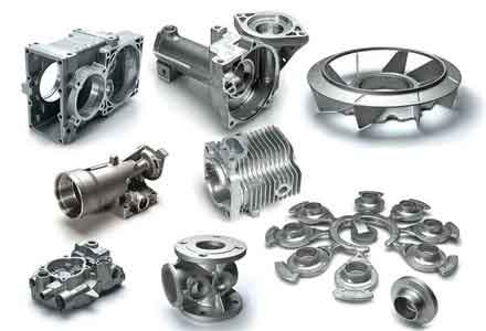
The primary challenge in machining these molds lies in the aspect ratio of the features. Deep, narrow cavities in the drag mold and tall, thin walls in the cope mold necessitate the use of long-reach, small-diameter tools for finishing and clearing corners. This dramatically increases the risk of tool deflection, vibration, and catastrophic breakage—events that are costly in terms of tooling, machine time, and potential workpiece damage. Therefore, the overarching philosophy of the optimization was to minimize the load and engagement on these fragile tools through intelligent sequencing and strategic roughing.
The foundational step for successful CNC machining is establishing a reliable and repeatable workpiece coordinate system (WCS). After squaring the raw casting block on a planer mill to create initial datum faces, the WCS for programming is defined digitally within the CAM system. For the drag mold, the parting plane is set as Z-zero. For the cope mold, Z-zero is set at the highest point of the core projection. Crucially, this digital WCS must be perfectly aligned with the physical setup on the machining center. This is achieved by first finish-machining the entire parting plane on the CNC machine, then using this pristine surface as the primary datum to accurately locate and indicate the positions for mold alignment features like dowel pin holes. Only after these alignment features are machined and the workpiece is securely re-clamped in its final orientation using them as reference, do we proceed with the intricate cavity machining. This rigorous approach ensures that all subsequent toolpaths are aligned with the physical part, eliminating errors from setup inconsistencies.
The heart of the optimization lies in the CAM programming strategy, which can be broken down into distinct, optimized phases. The goal is to leave as little material as possible for the small-diameter, long-reach tools to remove.
Phase 1: Volumetric Roughing with Large Tools
The first operation is aggressive material removal using the largest possible tool that can access the major volumes of the cavity. A Ø20mm flat-end mill is employed for a series of pocketing operations. Instead of generating a single, monolithic toolpath for the entire complex cavity—which would involve excessive air-cutting and non-productive time—the geometry is intelligently segmented into distinct machining regions. For the drag mold, this meant creating three separate, optimized pocketing paths. This regional roughing strategy significantly reduces overall cycle time. The primary objective here is not to achieve a fine finish or reach into fine details, but to efficiently evacuate the bulk of the material, leaving a uniform stock allowance for semi-finishing. The result after this stage is a shape that approximates the final form, but with all narrow ribs, deep corners, and fine details remaining as un-machined solid blocks of material.
Phase 2: Semi-Finishing and Localized Roughing
This phase is critical for protecting the subsequent finishing tools. The remaining material in the hard-to-reach areas must be removed with progressively smaller tools, but their engagement must be carefully controlled. We employ a strategy of “rest machining,” where the CAM software calculates the remaining stock left by the previous, larger tool. First, a Ø8mm flat-end mill is used to target areas inaccessible to the Ø20mm tool. The cutting parameters are meticulously tuned for this more fragile tool.
| Tool Parameter | Ø8mm Flat End Mill | Ø4mm Flat End Mill | Rationale |
|---|---|---|---|
| Cutting Diameter | 8 mm | 4 mm | Access to narrow ribs and pockets. |
| Flute Length | >65 mm | >65 mm | Must reach full cavity depth (~61.8mm). |
| Tool Material | Micro-grain Carbide | Micro-grain Carbide | High rigidity and wear resistance. |
| Helix Angle | 45° | 45° | Promotes smooth chip evacuation and reduces cutting forces. |
The machining parameters are equally vital. A key optimization is the use of helical or ramp entry motions instead of direct vertical plunging, which can shock and chip the cutting edges. The depth of cut and stepover are reduced relative to the larger tool.
| Cutting Parameter | Ø8mm Flat End Mill | Ø4mm Flat End Mill |
|---|---|---|
| Spindle Speed (S) | 3500 RPM | 4500 RPM |
| Feed Rate (F) | 800 mm/min | 600 mm/min |
| Plunge/Helical Feed Rate | 200 mm/min | 150 mm/min |
| Axial Depth of Cut (Ap) | 0.5 – 1.0 mm | 0.3 – 0.5 mm |
| Radial Stepover (Ae) | 30% of D (2.4mm) | 25% of D (1.0mm) |
| Stock to Leave | 0.2 mm | 0.15 mm |
The relationship between tool diameter (D), depth of cut (Ap), and safe material removal rate is paramount. A conservative rule of thumb for long-reach tools in hard materials is to limit the product of these forces. We can express a safety factor (SF) constraint for tool deflection as:
$$ SF \propto \frac{D^3}{L^4 \cdot (A_p \cdot A_e)} $$
where \( L \) is the tool overhang. To maintain a high SF and avoid breakage, reductions in \( D \) must be accompanied by disproportionate reductions in \( A_p \) and \( A_e \), which our parameter tables reflect.
Furthermore, for the Ø4mm tool attacking the deepest and most restricted areas, the machining zone (Z-range) for each operation is carefully bounded. Programming the tool to machine only within 5-10mm depth increments in these critical areas, rather than following the full cavity depth in one pass, prevents the tool from engaging with excessive side-wall material left from the previous step. This stepwise, depth-bound roughing is a cornerstone of the optimization, effectively preventing tool failure.
Phase 3: High-Quality Finishing
With a uniform and minimal stock allowance left, the final contour surfaces are generated using ball-nose end mills. The goal is to achieve the required surface finish for the sand casting parts, which directly affects the ease of sand mold stripping and the surface quality of the final casting. A Ø6mm ball mill is used for the majority of the 3D contour parallel or scallop finishing. The stepover is drastically reduced to create a smooth cusp height.
The maximum allowable scallop height (h) for a desired surface finish determines the stepover (s) for a ball mill of radius (R). The relationship is given by:
$$ s = 2 \sqrt{2 R h – h^2} $$
For a required finish on these critical sand casting parts, targeting a cusp height of h ≤ 0.01mm with an R=3mm tool gives a stepover s ≈ 0.49mm. In practice, we used a more conservative stepover of 0.12mm in the CAM software to ensure exceptional quality.
| Strategy | Tool Used | Path Pattern | Advantage for Sand Casting Mold | Disadvantage |
|---|---|---|---|---|
| Parallel Finishing | Ø6mm Ball | Linear, parallel passes | Fast, consistent finish on flat areas. | Poor finish on steep walls. |
| 3D Scallop/Contour | Ø6mm Ball | Constant stepover on 3D surface | Uniform finish on all geometries, ideal for complex sand casting part shapes. | Longer calculation and machining time. |
| Pencil Tracing | Ø4mm Ball | Follows sharp corners | Cleans out fillets and corners inaccessible to larger tools. | Very slow, light cuts. |
The finishing parameters prioritize surface integrity over speed. For the Ø6mm ball mill: S=4000 RPM, F=1200 mm/min, with a stepover of 0.12mm. For final detailing in tight corners with the Ø4mm ball mill, the parameters are further derated: S=5000 RPM, F=800 mm/min, stepover of 0.1mm. The use of high spindle speeds helps maintain adequate cutting speed at the small diameter of the ball, ensuring a clean shear cut rather than rubbing, which is essential for mold steel.
Phase 4: Drilling and Boring for Alignment
The final machining step involves creating the precision dowel pin holes for mold alignment. This is a sequential process designed to ensure hole straightness and diameter accuracy in the tough material. The process is a clear application of fundamental machining principles, optimized for this specific workpiece:
1. Center Drill: Creates a conical starter for accurate drill positioning.
2. Peck Drill with Ø16mm: Creates the pilot hole, using peck cycles to break chips.
3. Peck Drill with Ø27mm: Opens up the hole, reducing load on the final boring tool.
4. Boring with Ø33.5mm: Brings the hole to a precise size and excellent finish, just under the final dimension.
5. Reaming with Ø35mm: Achieves the final, high-tolerance diameter and surface finish for the press-fit dowel pins.
The feed (F) and speed (S) for drilling are calculated based on the tool diameter (D) and a material-specific constant (Cs for speed, Cf for feed per revolution). A simplified model for the initial drilling stage is:
$$ S = \frac{C_s \cdot 1000}{\pi D} \quad \text{(RPM)} $$
$$ F = f_r \cdot S \quad \text{(mm/min)} $$
Where \( f_r \) is the feed per revolution. For ductile iron, \( C_s \) is relatively low, and \( f_r \) is moderate to account for material toughness.
The implementation of this optimized programming strategy yielded significant and measurable benefits. Most notably, the incidence of tool breakage, particularly for the vulnerable Ø4mm and Ø8mm long-reach tools, was reduced to virtually zero. This eliminated unplanned stoppages for tool changeover, re-zeroing, and workpiece inspection, leading to a predictable and uninterrupted machining cycle. The regional roughing and depth-limited semi-finishing strategies directly reduced air-cutting time and machine idle periods, compressing the total machining time on the expensive CNC center. While the programming phase required more upfront engineering time—segmenting models, calculating rest material, and fine-tuning parameters for each tool—this investment was repaid multifold during production through reduced cycle times, eliminated scrapped workpieces from tool crashes, and lower tooling consumption. The reliable production of these high-quality molds ensures that the subsequent sand casting process yields consistent, dimensionally accurate rough sand casting parts, minimizing downstream machining issues.
In conclusion, the efficient machining of molds for complex sand casting parts is not merely a function of powerful CAM software but of a deeply reasoned and optimized process strategy. It requires a holistic understanding that bridges mold design for casting, metallurgy of the mold stock, mechanics of chip formation, and the dynamic limitations of cutting tools. The key takeaways are the critical importance of WCS alignment through machined datums, the strategic segmentation of toolpaths to minimize waste motion, the calculated, stepwise reduction of tool diameters with correspondingly conservative cutting parameters governed by deflection constraints, and the final application of high-quality finishing paths tuned for surface finish. By adhering to this philosophy, manufacturing engineers can reliably transform digital models of sand casting parts into robust, precision molds, driving down costs and increasing the reliability of the entire sand casting production chain.