
The relentless advancement of the power transmission industry has created a significant demand for large, high-integrity aluminum castings. Key among these are the thin-walled pressure vessels, or shells, used in high-voltage electrical equipment such as Gas-Insulated Switchgear (GIS) and instrument transformers. These sand casting parts present a formidable manufacturing challenge: they feature large geometries, complex shapes with numerous flanges, drastic variations in wall thickness (from 6-15mm on the body to 50-80mm on flanges), and must exhibit exceptional pressure tightness to contain insulating SF6 gas with annual leakage rates below 1%. Traditionally fabricated from welded steel or aluminum plate, modern designs are monolithic sand casting parts requiring zero leakage over a decade of service. This article details the first-person development and application of a robust Low-Pressure Sand Casting (LPSC) technology specifically engineered to produce these critical, high-performance components reliably and cost-effectively.
The core challenge lies in achieving simultaneously high mechanical strength, excellent electrical conductivity, and perfect soundness in a single casting process. Our approach integrates several innovative pillars: the formulation and purification of a superior Al-Si-Mg alloy; a novel mold positioning system using chills; a self-developed, crucible-sealed low-pressure casting machine for large molds; and advanced core-making techniques. This integrated system has been validated over more than a decade, producing thousands of sand casting parts that meet stringent international standards.
I. Foundational Metallurgy: Optimizing Alloy Composition and Melt Quality
The selection and control of the base alloy are paramount. The target alloy is based on the AlSi7Mg system (equivalent to A356, ZL101A). However, standard specifications are too broad for optimal performance in electrical applications. Our optimization focuses on the delicate balance between mechanical properties, castability, and crucially, electrical conductivity.
1.1 Strategic Elemental Control
Silicon (Si) content is critical. While it improves fluidity, essential for thin-walled sand casting parts, it severely degrades electrical conductivity. The relationship can be approximated by a linear reduction in conductivity with increasing Si. Therefore, we narrow the Si range significantly compared to standard specs:
$$ \text{Conductivity} \propto -\alpha[Si] $$
where $\alpha$ is a positive constant. Magnesium (Mg) forms the strengthening phase Mg$_2$Si. Its content directly influences tensile strength ($\sigma_b$) and elongation ($\delta$), but also affects conductivity. Through extensive experimentation, we determined the optimal window for Mg to be 0.3-0.5%, maximizing the property synergy for electrical housings.
| Element | Standard Range (Typical) | Optimized Range (This Work) | Primary Effect |
|---|---|---|---|
| Si | 6.5 – 7.5% | 6.8 – 7.2% | Fluidity ↗, Conductivity ↘ |
| Mg | 0.25 – 0.45% | 0.30 – 0.50% | Strength ↗ (via Mg$_2$Si), Conductivity ↘ |
| Fe | < 0.20% | < 0.15% | Elongation, Corrosion Resistance ↘ |
| P | Often not specified | < 0.001% | Coarsens Si, degrades Mech. & Elec. Prop. |
| Ca | Often not specified | < 0.002% | Increases melt oxidation, causes surface defects |
1.2 The Role of Trace Additions: Ti, B, Zr, and RE
Titanium (Ti) is a potent grain refiner via the formation of Al$_3$Ti particles, which act as heterogeneous nucleation sites. The nucleation potency increases dramatically above ~0.15% Ti. Beyond grain refinement, Ti can also getter hydrogen. We employ a “secondary Ti addition” technique, introducing a Ti-B-Zr-based salt compound (0.1 wt.% of melt) just before casting. This generates a fine dispersion of “active” Al$_3$Ti, TiB$_2$, and Al$_3$Zr nuclei, providing superior grain refinement compared to conventional Al-Ti master alloys where particles coarsen during remelting.
Boron (B) and Zirconium (Zr) further enhance grain refinement and contribute to hydrogen removal. Rare Earth (RE) elements like Ce and La modify the eutectic silicon morphology and, importantly, react with residual hydrogen to form stable hydrides (e.g., CeH$_3$), effectively suppressing the formation of gas porosity during solidification:
$$ [H] + \frac{1}{3}[Ce] \rightarrow \frac{1}{3}CeH_3(s) $$
This reaction lowers the hydrogen activity in the melt, directly combating a major source of leakage in pressure-tight sand casting parts.
1.3 Impurity Elimination: The Critical Case of Phosphorus (P)
A often-overlooked but crucial aspect is the control of Phosphorus. It originates primarily from the metallurgical-grade silicon used for alloying. P forms AlP compounds, which act as nucleation sites for primary silicon, leading to coarse, plate-like eutectic Si that severely degrades mechanical properties and conductivity. Using high-purity silicon to keep P below 10 ppm results in a naturally finer eutectic structure even before modification, significantly enhancing the performance of the final sand casting parts.
1.4 Advanced Melt Purification
Achieving a clean, gas-free melt is non-negotiable for leak-proof castings. Hydrogen is the main dissolved gas, and its solubility drops sharply upon solidification ($\Delta S_H$), leading to porosity:
$$ C_H^{liquid} \gg C_H^{solid} \Rightarrow H_{2}(g) \uparrow $$
We employ a multi-stage purification approach:
- Integrated Flux Treatment: A proprietary flux combining refining, modification, and slag-removal functions is introduced at 720°C. It generates inert gas bubbles that strip hydrogen and entrain oxide inclusions (mainly Al$_2$O$_3$). The reaction products are non-wetting and easily removed.
- Rotary Degassing: For central melting units, we utilize a rotary impeller degasser with pulsed argon injection. Pulsation creates finer bubbles, increasing the surface area-to-volume ratio for more efficient hydrogen removal according to the principles of mass transfer.
The efficiency of hydrogen removal ($\eta_H$) can be related to bubble size ($d_b$), gas flow rate ($Q_g$), and treatment time ($t$):
$$ \eta_H \propto \frac{Q_g \cdot t}{d_b} $$
Finer bubbles ($d_b \downarrow$) significantly increase efficiency ($\eta_H \uparrow$).
II. Precision Sand Molding and Low-Pressure Casting Process
The casting process must translate high-quality metal into a sound, dimensionally accurate component. Our LPSC process for large sand casting parts incorporates key innovations in mold design and metal delivery.
2.1 Chill Design, Treatment, and the Precision Positioning System
Thick flange sections are prone to shrinkage porosity, which manifests as micro-leakage paths on sealing surfaces. The strategic use of chills is essential. However, conventional chill practice is inadequate. We have developed a standardized protocol:
- Material: Ductile iron is used for its good thermal conductivity and resistance to thermal cracking.
- Surface Engineering: Chills are machined, sandblasted, and undergo salt bath nitriding. This creates a dense, oxidation-resistant layer (Fe$_3$N, Fe$_4$N). An untreated steel chill rusts; the porous rust (Fe$_3$O$_4$·xH$_2$O) releases moisture upon contact with molten aluminum, leading to hydrogen pickup and subsequent pinholing: $$ 2Al + 3H_2O \rightarrow Al_2O_3 + 6[H] $$
- Venting: Machined grooves (20mm apart) on the chill face prevent air entrapment.
The most significant innovation uses these precision-machined chills as part of the mold alignment system. In traditional sand casting for such parts, the core prints (locators) are made of sand, leading to clearances of 1.0-1.5mm and wall thickness variations ($\Delta t$) of 2-3mm. Our method replaces the sand core print with a machined metal plate attached to the core. This metal “print” fits into a socket formed by the ring of chills placed around the flange, creating a near-metal-die alignment with a clearance of only ~0.5mm.
| Feature | Traditional Method | Improved Method |
|---|---|---|
| Core Print Material | Sand | Machined Ductile Iron |
| Core Seat/Socket | Sand Mold | Ring of Machined Chills |
| Typical Clearance | 1.0 – 1.5 mm | ~0.5 mm |
| Wall Thickness Variation ($\Delta t$) | 2 – 3 mm | < 1 mm |
| Primary Function | Basic Location | Precision Location + Improved Cooling |
This system dramatically improves the dimensional accuracy of large, complex sand casting parts.
2.2 The Low-Pressure Sand Casting Process & Equipment
For large, thin-walled pressure vessels, gravity sand casting is problematic: turbulent metal entry causes oxide entrapment, and horizontal pouring impedes effective feeding of thick sections. Low-Pressure Casting is the optimal solution. It offers a laminar, bottom-up fill through a riser tube, eliminating turbulence. More importantly, it applies a sustained pressure (typically 0.5-0.8 bar) during solidification, dramatically improving feeding efficiency and reducing shrinkage porosity.
The pressure profile is critical. After mold filling, pressure is increased and held according to a defined curve $P(t)$ until the casting gate solidifies. The solidification time $t_s$ for a section of modulus $M$ can be estimated by Chvorinov’s rule:
$$ t_s = k \cdot M^n $$
where $k$ is the mold constant. The applied pressure $P$ helps overcome the pressure drop $\Delta P_{feeding}$ in the mushy zone to suppress microporosity formation.
Standard commercial low-pressure machines use a “furnace-sealed” design, where the mold sits on top of the furnace shell, which bears the entire weight. This is unsuitable for our massive sand molds, which can weigh over 13 tons with dimensions up to 3m. We therefore developed a proprietary crucible-sealed system. In this design, the mold’s weight is transferred directly to the foundation via a robust support structure. The pressure vessel is the refractory crucible itself, made from a specially formulated high-temperature alloy. This design offers several advantages:
- Handles extreme mold weights and sizes.
- Eliminates pressure fluctuations common in large furnace-sealed systems.
- Extends furnace lining life as it bears no load.
- The crucible, despite enduring pressure at high temperature, achieves a service life exceeding 150 heats due to optimized material and casting process.
This custom LPSC equipment is the enabling hardware for producing these mammoth, high-quality sand casting parts.
III. Enabling Technologies: Core Making and Process Simulation
3.1 High-Precision, High-Finish Core Making
Some components, like certain connector housings, have small, inaccessible internal passages that require an as-cast smooth surface to prevent electrical corona discharge. Producing such cores with traditional methods is impossible. We developed a “Negative Pattern by Positive Model” technique. A precise, machined metal positive model of the desired internal cavity is first created. A non-shrink silicone rubber is then cast around it to create a perfect negative cavity. A modified, highly collapsible sodium silicate sand (with proprietary additives for improved breakdown) is then rammed into this rubber mold. The resulting sand core is an exact replica of the original metal model, offering exceptional surface finish and dimensional accuracy. After casting, the sand core collapses easily under vibration, leaving a clean, smooth internal surface that requires no machining.
3.2 Process Simulation and CAD
Trial-and-error for multi-ton sand castings is prohibitively expensive. We employ full 3D CAD modeling and solidification simulation (using Finite Difference/Volume methods) during process design. The energy conservation equation governing solidification is solved:
$$ \rho c_p \frac{\partial T}{\partial t} = \nabla \cdot (k \nabla T) + \rho L \frac{\partial f_s}{\partial t} $$
where $\rho$ is density, $c_p$ is specific heat, $k$ is thermal conductivity, $L$ is latent heat, and $f_s$ is solid fraction. This allows us to predict shrinkage and potential defect locations in virtual prototypes, optimizing feeder and chill placement before any metal is poured, drastically reducing development time and cost for new sand casting parts.
IV. Application Spectrum and Production Validation
This integrated Low-Pressure Sand Casting technology has been in production for over fifteen years. It initially targeted high-voltage electrical equipment but has since expanded to other demanding sectors. The process is versatile, working successfully with various sand systems: traditional dry clay sand, furan resin sand, and eco-friendly water-glass sand.
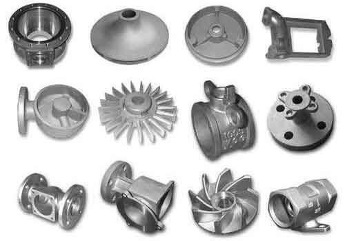
The portfolio of produced sand casting parts is extensive:
- Electrical Industry: 500kV GIS shells (ø1280mm x 1480mm, 420kg), 345kV circuit breaker tanks (ø870mm x 2350mm, 620kg), instrument transformer housings, and interrupters.
- Transportation: Large diesel engine blocks, crankcases for heavy-duty trucks and special vehicles, and turbocharger housings.
- Specialized Equipment: Housings for CT and MRI medical scanners.
Cumulatively, over 200 different part designs and more than 50,000 castings have been manufactured. The technology has enabled foundries to become qualified suppliers to global leaders like ABB, Siemens, and Alstom. The castings consistently pass stringent hydrostatic tests and helium leak detection, meeting the critical <1% annual SF6 leakage rate. The optimized alloy ensures tensile strength ($\sigma_b$) > 230 MPa, elongation ($\delta$) > 5%, and electrical conductivity > 40% IACS, fulfilling all functional requirements for high-voltage application sand casting parts.
V. Summary of Key Advantages
| Aspect | Technology/Feature | Benefit for Large Sand Casting Parts |
|---|---|---|
| Metallurgy | Optimized AlSi7Mg with RE/B/Zr; P control; Secondary Ti addition; Integrated flux refining. | Superior strength-ductility-conductivity balance; Fine, sound microstructure; Low gas content. |
| Mold & Core | Machined chills (nitrided) as alignment seats; Metal core prints; “Negative by Positive” core making. | Wall thickness variation <1mm; Eliminates sealing face porosity; Excellent internal surface finish. |
| Casting Process | Low-Pressure Sand Casting with crucible-sealed, self-designed equipment. | Laminar fill; Effective pressurized feeding; Capable of handling molds >13 tons. |
| Process Design | 3D CAD and Solidification Simulation. | Rapid development; High first-pass yield; Optimized feeding/chilling. |
In conclusion, the development of this comprehensive Low-Pressure Sand Casting technology provides a reliable, scalable, and high-quality manufacturing route for large, thin-walled, and complex aluminum castings. By synergistically advancing alloy science, precision mold engineering, and robust process equipment, it solves the critical challenges of leakage, dimensional accuracy, and property consistency. This makes it an indispensable solution for producing the demanding, high-integrity sand casting parts required by modern high-voltage electrical and heavy engineering industries.