
In the realm of sand casting, the production of high-quality sand casting parts often hinges on the efficiency and precision of pattern extraction. As an engineer specializing in foundry equipment, I have extensively studied and designed universal pattern stripping machines, commonly known as漏模机, which play a pivotal role in中小型铸造 enterprises. These machines enable the removal of patterns from sand molds without flipping the mold box, crucial for complex sand casting parts with minimal draft angles and significant heights. With the market demand shifting towards small-batch, multi-variety production, optimizing these machines for通用性 and rapid design has become imperative. In this analysis, I will delve into the working principles, structural design, classifications, and传动 mechanisms, emphasizing how they enhance the manufacturing of diverse sand casting parts.
The core function of a universal pattern stripping machine is to facilitate the stripping of patterns from compacted sand molds, ensuring dimensional accuracy and reducing修型 time. This process is vital for producing intricate sand casting parts, such as engine blocks or pump housings, where traditional hand molding falls short. The machine typically consists of several key components: a传动机构 for motion transfer, a导向机构 for precise alignment, an起模机构 for pattern extraction, and a机架 for structural support. By托住 the sand mold via a漏板框, the pattern can be漏出 or顶出, minimizing damage to the mold cavity. This mechanism is particularly beneficial for sand casting parts that require tight tolerances and smooth surfaces.
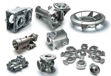
From a design perspective, the working principle revolves around controlled vertical movement. In顶箱漏模机, the sand box is lifted by顶杆 while the pattern remains on the worktable; in落模漏模机, the pattern is lowered through a漏模板. The gap between the pattern and the漏板框 is critical, typically ranging from 0.5 to 1.5 mm, to prevent sand tear and ensure clean extraction for sand casting parts. I often calculate the required stripping force using the formula: $$ F_s = \mu \cdot P_c \cdot A_p $$ where \( F_s \) is the stripping force, \( \mu \) is the friction coefficient between sand and pattern (usually 0.2–0.4 for clay-bonded sand), \( P_c \) is the compaction pressure of the sand mold (in MPa), and \( A_p \) is the contact area between the pattern and sand (in mm²). For instance, for a medium-sized sand casting part like a gear housing, with \( A_p = 5000 \, \text{mm}^2 \), \( P_c = 0.5 \, \text{MPa} \), and \( \mu = 0.3 \), the stripping force would be: $$ F_s = 0.3 \times 0.5 \times 5000 = 750 \, \text{N} $$ This force dictates the design of the传动机构 to ensure smooth operation.
The structural design can be broken down into detailed subsystems. Below is a table summarizing the main components and their functions:
| Component | Function | Design Considerations |
|---|---|---|
| Transmission Mechanism | Converts manual input into vertical motion for pattern stripping. | Must provide sufficient torque and speed;常见 types include gear-rack and lever systems. |
| Guidance Mechanism | Ensures straight-line movement of the pattern or sand box during stripping. | Precision is key to avoid tilting; options include sleeve-type or guide-rod configurations. |
| Pattern Stripping Mechanism | Directly engages with the pattern to lift or lower it relative to the sand mold. | Designed to handle varying pattern heights and weights for different sand casting parts. |
| Frame | Provides structural integrity and houses all components. | Should be rigid yet lightweight; often made from steel or cast iron for stability. |
| Pre-positioning机构 | Locks the pattern or sand box at a specific height during operation. | Enables quick adjustments and enhances safety during the stripping of sand casting parts. |
In terms of classification, pattern stripping machines are primarily divided into two types based on their operation mode.顶箱漏模机, also known as top-box stripping machines, use顶杆 to lift the sand box, leaving the pattern behind. This is ideal for sand casting parts with deep pockets or undercuts.落模漏模机, or drop-pattern stripping machines, involve lowering the pattern through a fixed漏模板, suitable for patterns with minimal draft. The choice depends on the geometry of the sand casting parts being produced. I have compiled a comparison table to highlight the differences:
| Type | Operation | Advantages | Limitations | Typical Application for Sand Casting Parts |
|---|---|---|---|---|
| 顶箱漏模机 (Top-Box) | Sand box is lifted vertically via顶杆. | Reduces sand fall-in; good for complex patterns. | Requires precise alignment; higher machine height. | Engine blocks, valve bodies. |
| 落模漏模机 (Drop-Pattern) | Pattern is lowered through a漏模板. | Simpler structure; faster for shallow patterns. | Risk of sand damage if间隙 is too large. | Gears, brackets, flat plates. |
The传动方式 is another critical aspect, especially in manual machines common in中小型 enterprises. These include凸轮式 (cam-driven),偏心式 (eccentric-driven),杠杆式 (lever-driven), and齿条式 (rack-and-pinion driven). Each has distinct characteristics in terms of stroke length and ease of fabrication. For sand casting parts requiring varied stripping heights, the齿条式 system is often preferred due to its adjustability. The stroke length \( H \) can be calculated as: $$ H = n \cdot p $$ where \( n \) is the number of teeth engaged on the rack, and \( p \) is the pitch of the teeth (in mm). For example, with \( p = 5 \, \text{mm} \) and \( n = 20 \), the stroke is \( H = 100 \, \text{mm} \), sufficient for most medium-sized sand casting parts. Below is a table detailing the传动方式:
| 传动方式 | Mechanism | Stroke Range (mm) | Advantages | Common Use in Sand Casting Parts |
|---|---|---|---|---|
| Cam-driven | Uses a rotating cam to convert rotary motion to linear motion. | 10–50 | Simple construction; quick action. | Small, simple patterns like washers or fittings. |
| Eccentric-driven | Employs an eccentric shaft for oscillating motion. | 20–80 | High force transmission; durable. | Medium-weight parts like flanges or hubs. |
| Lever-driven | Utilizes levers to amplify manual force. | 15–60 | Ergonomic; low cost. | Low-volume production of intricate sand casting parts. |
| Rack-and-pinion | Features a gear meshing with a齿条 for precise control. | 50–200 | Adjustable stroke; suitable for varied pattern heights. | Large or complex parts like pump casings or machinery bases. |
Guidance mechanisms are essential for maintaining accuracy during stripping. I categorize them into three types:导套式 (guide sleeve type),套筒式 (sleeve type), and顶杆配短导套式 (guide rod with short sleeve type). The choice impacts the precision of sand casting parts. For instance,套筒式 offers high定位精度 but is harder to manufacture, making it ideal for落模漏模机 where sand tear must be minimized. The allowable misalignment \( \delta \) can be derived from: $$ \delta = \frac{H_g}{L_g} \cdot d $$ where \( H_g \) is the guidance height, \( L_g \) is the length of the guide, and \( d \) is the clearance. For sand casting parts with tight tolerances, \( \delta \) should be less than 0.1 mm to prevent错箱 issues.
When designing these machines, I prioritize通用性 to accommodate diverse sand casting parts. Key considerations include: light weight and simplicity for ease of移动, economic viability through standardization of components, and safety features to prevent operator injury. For example, the机架 height should not exceed 1200 mm to ensure ergonomic access, and防尘 measures are crucial to handle sand ingress, which can affect the dimensional accuracy of sand casting parts. The template and sand box定位 design also plays a vital role; I often use止口定位 for round boxes and销边销定位 for rectangular ones, ensuring错箱量 within 0.5–1.0 mm for high-precision sand casting parts.
To illustrate the structural details, let’s examine two common configurations: the齿条式顶箱漏模机 and齿条式落模漏模机. In the顶箱 version, the传动机构 includes a手柄,传动轴,齿轮, and齿条式升降导柱. When the手柄 is actuated, motion transfers through the齿轮 to the齿条, lifting the升降托板 and顶杆, which in turn raise the sand box. A预定位机构 locks the box at the desired height, allowing the pattern to be stripped cleanly for sand casting parts. The force equilibrium during lifting can be expressed as: $$ T \cdot r = F_s \cdot h $$ where \( T \) is the torque applied via the手柄, \( r \) is the gear radius, and \( h \) is the effective lever arm. This ensures that the manual effort is optimized for stripping various sand casting parts.
In the落模 version, the pattern is attached to a模样定位板 that moves vertically along齿条式导柱. Upon operating the手柄, the pattern descends through the漏模板, leaving the sand mold intact. This setup is excellent for sand casting parts with vertical sides, as it reduces修型 time. The stripping speed \( v \) can be controlled by the齿轮 ratio: $$ v = \omega \cdot r_p $$ where \( \omega \) is the angular velocity of the手柄, and \( r_p \) is the pitch radius of the pinion. For consistent production of sand casting parts, \( v \) should be maintained at 0.1–0.3 m/s to avoid sudden movements that might damage the mold.
Advantages of universal pattern stripping machines are manifold. They are structurally simple, require no external power source, and are easily fabricated with standard materials. Their通用性 allows one machine to handle multiple patterns for different sand casting parts, reducing investment and floor space. By enabling quick pattern changes via interchangeable漏模板 and托模板, they support small-batch production of sand casting parts. Moreover, the预定位行程 can be微调 to suit pattern heights, enhancing flexibility. However, drawbacks exist: these machines are relatively笨重 compared to simple templates, have higher initial costs, and may accumulate落砂 under the托模板, necessitating regular cleaning to maintain precision for sand casting parts.
In my design practice, I emphasize优化设计 and可靠性设计. For instance, I use standardized圆钢 for立柱 to reduce costs and ensure interchangeability. The预定位机构 often incorporates弹簧-loaded销 for automatic locking, improving operational safety when handling heavy sand casting parts. Additionally, I integrate微调装置 such as nuts and bolts to fine-tune the stripping height, accommodating variations in pattern尺寸 for sand casting parts. The overall design process involves iterative calculations to balance strength and weight, often using formulas like the bending stress on the机架腿: $$ \sigma_b = \frac{M \cdot c}{I} $$ where \( M \) is the bending moment due to the weight of sand casting parts and machine components, \( c \) is the distance from the neutral axis, and \( I \) is the moment of inertia. Ensuring \( \sigma_b \) remains below the material yield strength is crucial for durability.
To further elaborate on the application range, these machines excel in producing sand casting parts that demand high dimensional stability, such as automotive components or industrial machinery parts. The漏模板 design must align with the pattern’s轮廓, and I often employ CAD software to simulate the stripping process for complex sand casting parts. This helps in optimizing the间隙 and reducing trial-and-error during fabrication. Below is a table summarizing key design parameters for different sizes of sand casting parts:
| Sand Casting Part Size | Pattern Height (mm) | Recommended Machine Type | Stroke (mm) | Stripping Force (N) |
|---|---|---|---|---|
| Small (e.g., fittings) | 30–100 | Cam-driven顶箱机 | 40–60 | 300–600 |
| Medium (e.g., housings) | 100–250 | Rack-and-pinion落模机 | 80–150 | 600–1500 |
| Large (e.g., frames) | 250–500 | Rack-and-pinion顶箱机 | 150–200 | 1500–3000 |
In conclusion, universal pattern stripping machines are indispensable tools for enhancing the production efficiency and quality of sand casting parts in中小型 foundries. Through careful structural design and classification, they offer a versatile solution for diverse pattern geometries. By incorporating robust传动 and guidance mechanisms, along with safety and adjustability features, these machines can be tailored to specific needs. As the demand for customized sand casting parts grows, ongoing optimization and standardization will further solidify their role in modern铸造 equipment. My experience confirms that a well-designed漏模机 not only reduces labor intensity but also ensures consistent output of high-integrity sand casting parts, ultimately contributing to competitive advantage in the global market.