
The production of complex, thin-walled castings like automotive engine cylinder blocks presents a significant challenge in high-volume sand casting operations. These sand casting parts demand not only dimensional accuracy but also production rates that match the pace of modern foundry lines. The core setting fixture, or core jig, stands as a pivotal piece of tooling in this process. Its primary functions are twofold: to ensure the precise assembly of multiple sand cores into a cohesive unit (the “core package”) and to facilitate the accurate and repeatable placement of this package into the mold cavity. Beyond these fundamental requirements, an optimal fixture must also be structurally sound, reliable, operator-friendly, and cost-effective to manufacture. Despite its critical role, dedicated literature on the subject is scarce. Furthermore, based on my extensive observations across numerous foundries, the design and application of these fixtures for cylinder blocks often exhibit considerable room for improvement. This article, therefore, aims to share insights and methodologies developed through years of practical experience in designing, building, and utilizing these fixtures, focusing on key areas for optimization.
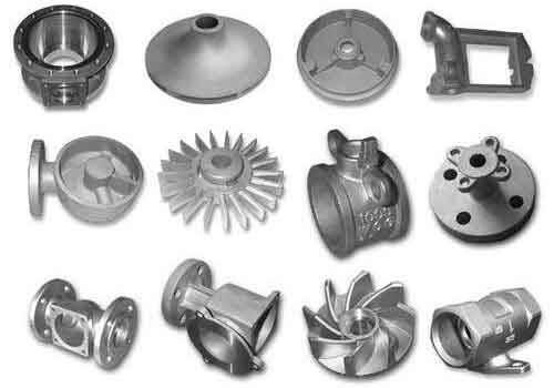
The performance and efficiency of producing sand casting parts like cylinder blocks are heavily influenced by the core setting fixture’s architecture. Based on their balancing mechanism, these fixtures can be broadly categorized into two types, each with distinct implications for design complexity, cost, and usability.
1. Comparative Analysis of Fixture Frameworks
The choice between a multi-story and a single-story frame structure is fundamental. A multi-story fixture employs two or more stacked frame layers connected by guide posts or similar elements. The primary perceived advantage is enhanced stability during the vertical travel of the fixture, both when picking up the core package from the assembly table and when lowering it into the mold. However, this structure introduces several critical drawbacks.
Firstly, it leads to increased complexity and manufacturing cost. To mitigate excessive weight, the secondary frames are often machined from lightweight alloys like aluminum, yet the overall assembly remains cumbersome. The design effort multiplies, and the material and machining costs significantly outpace those of simpler alternatives. Secondly, the inherent weight and bulk make the fixture less maneuverable, increasing operator fatigue and energy consumption on the production line. The table below summarizes the key trade-offs:
| Feature | Multi-Story Structure | Single-Story Structure |
|---|---|---|
| Structural Complexity | High (multiple frames, guide posts) | Low (single rigid frame) |
| Manufacturing Cost | High (more parts, precision alignment) | Low |
| Fixture Weight | High (even with lightweight alloys) | Moderate to Low |
| Perceived Stability | High (in theory) | Conditional (requires balancing system) |
| Operational Ease | Lower due to weight and size | Higher |
Conversely, the single-story structure employs a monolithic, rigid frame. Its superiority lies in its simplicity, reduced weight, and lower cost. A common misconception is that this design sacrifices stability. In practice, this is effectively resolved by integrating a system of synchronized balancing rods or bars. Typically, three or four such rods, strategically placed, ensure perfectly guided and stable vertical movement, matching or even exceeding the smooth operation of multi-story designs. This balancing system is the crucial, often overlooked, element that makes the single-story frame the optimal and most widely adopted choice for high-volume production of sand casting parts.
2. Advanced Design of the Fixture Body
Beyond mere functionality, the fixture body presents an opportunity for refined engineering and aesthetic design. In a modern foundry, tooling should reflect the same standards of quality and precision as the sand casting parts it helps produce. Optimizing the body involves considerations of surface finish, proportional design, and structural efficiency.
A key shift from traditional design is moving from an “external rib, internal flat” pattern to an “internal rib, external smooth” philosophy. All exterior surfaces visible to the operator should be finely machined or finished. This not only enhances the professional appearance of the tooling, moving away from the “rough and ready” stereotype of foundry equipment, but also improves cleanliness and reduces areas for sand accumulation.
The application of the Golden Ratio principle (approximately 1.618) brings a harmonious proportion to the design. This can be applied to the overall frame dimensions and the placement of features. For instance, the width of the fixture body can be designed as a function of its length:
$$ \text{Body Width} \approx \frac{\text{Body Length}}{1.618} $$
Similarly, the positions of the balancing rods and the size of access windows on the side panels can be determined using this ratio, creating a visually balanced and coordinated structure that is instinctively perceived as well-designed.
While cast iron or aluminum is typically chosen for the body to ensure rigidity, over-engineering is common. Walls are often excessively thick (25-35 mm), adding unnecessary weight. Through finite element analysis and practical validation, it has been established that a wall thickness (t) in the range of 12-15 mm, reinforced with an optimized rib pattern, is sufficient for the dynamic loads encountered. The required second moment of area (I), a measure of bending stiffness, for a rectangular beam section representing a frame member is given by:
$$ I = \frac{b \cdot t^3}{12} $$
where ‘b’ is the width of the section. By strategically adding ribs, the effective ‘b’ is increased locally, allowing the thinner wall (t) to achieve the necessary stiffness (I) with significantly less material, thus reducing mass and inertial loads during operation.
3. Optimization of Core Clamping Mechanisms
The clamping system secures the assembled sand cores within the fixture for transfer. The two predominant types are rotary and translational (linear) actuators, each suitable for different production contexts.
Rotary Clamping Systems: Typically powered by pneumatic cylinders, these systems use a linkage to convert the cylinder’s linear motion into a rotating action of the clamp arm or block. Configurations vary from using multiple smaller cylinders (one per side) to a single large central cylinder actuating all clamps via a complex linkage. Their main advantage is high speed and automation compatibility, making them ideal for high-cycle, fully automated lines dedicated to a single part number. However, their fixed clamping points offer little to no adaptability. The clamp geometry is specific to one core package outline, rendering the fixture unsuitable for even similarly sized sand casting parts. This lack of flexibility, coupled with higher design and build precision requirements, increases cost and limits application.
Translational (Linear) Clamping Systems: In this design, the clamp arms or blocks move in a straight line, typically guided by linear bearings or rods. This motion can be powered pneumatically or manually. The pneumatic translational system matches the speed of rotary systems while overcoming their key drawback: adaptability. By incorporating adjustable stop blocks or programmable logic for pneumatic actuators, the clamping points can be modified to accommodate a family of similar core packages, greatly enhancing the fixture’s versatility for different sand casting parts.
The manual translational system, while slower, offers exceptional robustness, consistent clamping force, and independence from plant air supply. It is the optimal choice for lower-volume production, job-shop environments, or for sand casting parts with very similar geometries run on the same line. The clamping force (F_c) in a manually cranked system can be easily estimated and controlled by the operator through a leadscrew mechanism, where the torque (T) applied relates to the force:
$$ T = F_c \cdot \frac{p}{2\pi\eta} $$
Here, ‘p’ is the leadscrew pitch and ‘\eta’ is the efficiency. This provides a reliable, feel-based method for securing fragile sand cores without over-stressing them.
4. Precision Core Locating and Positioning
Accurate location of the core package within the fixture is non-negotiable for producing dimensionally correct sand casting parts. While some designs employ perimeter locating blocks on all sides to prevent core shift after pick-up, the most critical locating function is often vertical.
The fixture must positively control the final height (Z-position) of the core package relative to the mold parting line. A missing or inadequate vertical stop system leads to cores not seating fully in the drag half of the mold. This forces operators to manually tap or press the cores down and use gauges to verify position, introducing variability and slowing the process. Therefore, the design must incorporate robust, wear-resistant pads or blocks that definitively set the core package height. The location of these pads is derived directly from the casting drawing, accounting for core print dimensions and the required cavity geometry. Their contact surface area (A) must be sufficient to withstand the downward force (F) during setting without embedding into the sand core, which is governed by the core sand’s compressive strength ($\sigma_c$):
$$ A \geq \frac{F}{\sigma_c} $$
Ensuring this condition prevents damage to the cores and maintains consistent positioning cycle after cycle.
5. Holistic Design Integration and Material Selection
The ultimate performance of the fixture stems from the integration of all subsystems. The frame, clamping mechanism, locators, and balancing system must work in harmony. Material selection plays a key role here. A summary of common choices and their properties is useful:
| Component | Recommended Material | Key Properties & Rationale |
|---|---|---|
| Main Fixture Body | Cast Iron (GGG-40/50) or Cast Aluminum (AlSi10Mg) | High damping (CI), good stiffness, excellent castability for complex shapes. Aluminum reduces weight. |
| Clamp Arms & Wear Parts | Through-hardened Steel (e.g., 1.7131/16MnCr5) or Tool Steel | High surface hardness for wear resistance, good core toughness. |
| Linear Guides/Bushings | Hardened Steel Shafts with Bronze or Polymer Bushings | Low friction, high wear resistance, tolerance to foundry dust. |
| Locating Pads/Stops | Hardened Steel or Ceramic Inserts | Extreme abrasion resistance to maintain precision against sand cores. |
Furthermore, designing for maintainability is crucial. Wear parts like locating pads and clamp faces should be easily replaceable. Lubrication points for moving parts should be accessible. For pneumatic systems, quick-disconnect fittings and built-in filter-regulator-lubricator units protect the actuators from contaminated plant air, a common cause of failure in the production of sand casting parts.
6. Conclusion: The Philosophy of Optimized Tooling Design
The journey toward an optimal core setting fixture extends beyond applying engineering formulas. It involves a mindset that values simplicity, elegance, and practicality in equal measure. A successful designer in this field must be both a technical expert, deeply understanding the processes of creating sand casting parts, and an implicit aesthetician, striving to create tooling that is not only functionally flawless but also a testament to good design. This means challenging entrenched conventions, whether it’s the presumed need for multi-story frames or the overbuilding of components. It requires a commitment to continuous improvement, where today’s solutions actively seek to refine and replace yesterday’s standards. By focusing on structural optimization of the frame, intelligent selection of clamping and locating systems, and careful attention to detail in manufacturing and integration, we can develop core setting fixtures that elevate the quality, efficiency, and reliability of producing even the most complex sand casting parts.