
In the realm of casting production, the green sand mold process utilizing clay-bonded sand remains extensively employed for manufacturing gray iron castings. This method offers significant advantages: raw materials are inexpensive and abundantly available, molds achieve sharp contours, shaping is convenient, drying is unnecessary, production cycles are short, and sand removal is facile. However, inherent drawbacks include relatively low mold strength, moisture content, and a propensity for casting defects such as gas holes, slag inclusions, and sand holes. Among these, slag inclusions and sand holes are frequently confounded during defect identification in industrial settings. This article, from my perspective as a practitioner, delves into a comparative analysis of these two defect types, elucidating their morphological characteristics, discrimination methodologies, and preventive measures. The term ‘slag inclusion’ will be recurrently emphasized to underscore its distinct nature and prevalence.
The green sand process, while cost-effective, introduces challenges due to the presence of water and the mechanical properties of the sand mixture. Defects like slag inclusions and sand holes not only compromise the structural integrity and aesthetics of castings but also lead to increased scrap rates and economic losses. Accurate identification is the cornerstone of effective quality control and process optimization. This discourse aims to provide a comprehensive guide, moving from fundamental visual inspection to advanced analytical techniques, supplemented with theoretical models and practical data. Tables and mathematical formulations will be employed to consolidate information and illustrate underlying principles.
Fundamental Characteristics: A Comparative Foundation
Understanding the intrinsic features of slag inclusions and sand holes is paramount. Both manifest as irregular cavities on or within the casting, but their genesis and composition differ markedly.
Slag Inclusions (Slag Defects): These defects arise from the entrapment of non-metallic, predominantly oxide, impurities within the molten metal. These impurities may originate from melting fluxes, refractory linings, oxidation products, or eroded mold materials. Upon solidification, they are encapsulated, appearing as uneven, often shallow, cavities. Key characteristics include:
- Color: Typically appear in shades of brownish-white or white, mirroring the color of the slag system from which they originate.
- Morphology: Highly irregular shape with a rough,凹凸不平 (uneven) surface. Under magnification, the interface often exhibits angular features.
- Adhesion: The slag material is tenaciously bonded to the metal matrix. Conventional cleaning methods like shot blasting are often ineffective at removing the embedded slag, merely polishing the exposed surface.
- Composition: Primarily consists of complex oxides, silicates, or other non-metallic compounds. A common simple representation for iron oxide slag is FexOy.
Sand Holes: These defects result from the mechanical erosion or collapse of the mold or core, leading to the encapsulation of loose sand grains or clusters by the advancing metal front. Their features are distinct:
- Color: The cavity often appears褐黑色 (brownish-black), closely resembling the color of the casting metal, as it is essentially a void containing sand.
- Morphology: Irregular shape, but the cavity walls and any retained sand particles exhibit sharp, angular geometries characteristic of sand grains.
- Cleanability: Shot blasting or vigorous cleaning can often dislodge the loose sand from the hole, revealing the underlying metallic surface of the cavity wall.
- Composition: The cavity contains silica sand (SiO2) or other molding aggregates, not metallurgical slag.
| Feature | Slag Inclusion | Sand Hole |
|---|---|---|
| Primary Cause | Entrapment of non-metallic impurities from melt | Erosion/collapse of mold/core, sand entrapment |
| Typical Color | White, Brownish-white | Brownish-black, metallic |
| Surface Texture | Rough, often glossy slag surface | Gritty, angular sand particle surfaces |
| Adhesion to Metal | Strong chemical/physical bond | Weak mechanical entrapment |
| Effect of Shot Blast | Slag remains; surface may polish | Sand is removed; metal cavity exposed |
| Typical Composition | Oxides (e.g., FeO, SiO2, Al2O3 complexes) | Molding sand (SiO2 with binders) |
| Common Location | Upper surfaces, final solidification zones | Anywhere, often near gates or sharp corners |
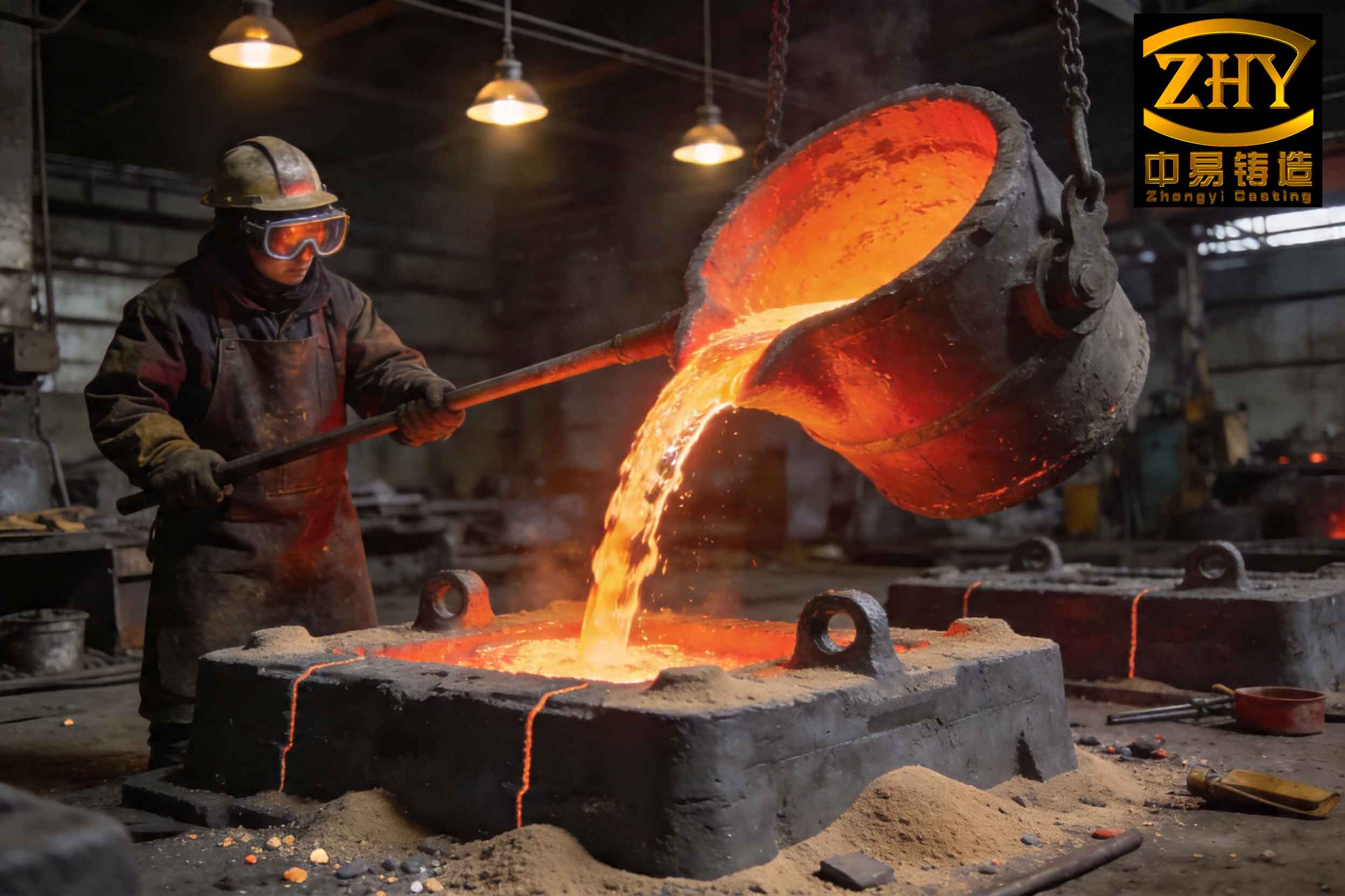
The visual distinction, as hinted in the linked image, can sometimes be subtle, necessitating systematic discrimination protocols.
Hierarchical Discrimination Methodology
In practical foundry operations, a tiered approach to defect analysis is most efficient, escalating in complexity as needed.
Level 1: Visual Inspection and Process Knowledge
Experienced technicians leverage nuanced observation and contextual process understanding. The color and macroscopic morphology provide initial clues. A defect appearing white or lustrous on a gray iron casting’s upper surface strongly suggests a slag inclusion. Knowledge of the melting and pouring practices—such as inadequate slag removal or turbulent gating—can corroborate this. The probability of misidentification at this stage can be modeled based on inspector experience and defect clarity. Let’s define a simple confidence score \( C_v \) for visual identification:
$$ C_v = \alpha E + \beta D + \gamma K $$
where \( E \) represents the experience factor of the inspector (0 to 1), \( D \) is the distinctness of defect features (0 to 1), \( K \) is the consistency with known process conditions (0 to 1), and \( \alpha, \beta, \gamma \) are weighting coefficients summing to 1. For clear cases, \( C_v \) may exceed 0.8, warranting direct action. However, for lower scores, progression to the next level is advised.
Level 2: Mechanical Cleaning Test
This is a straightforward, destructive test. The suspect area is subjected to aggressive shot blasting or grit blasting. The outcome is diagnostic:
- If the cavity contents are easily removed, leaving a clean, metallic-walled hole, the defect is conclusively a sand hole. The energy required for removal is relatively low, corresponding mainly to breaking mechanical interlocking.
- If the cavity contents cannot be removed or only a polished surface is achieved, the defect is indicative of a slag inclusion. The adhesion energy of the slag to the metal is high, often involving chemical bonds. The energy balance can be considered:
$$ E_{\text{blast}} > E_{\text{adhesion}} \quad \text{(for removal)} $$
For slag inclusions, \( E_{\text{adhesion}} \) is typically too high for standard cleaning energies.
Level 3: Advanced Microstructural and Compositional Analysis
When ambiguity persists or for root-cause analysis, advanced techniques like Scanning Electron Microscopy (SEM) coupled with Energy Dispersive X-ray Spectroscopy (EDS) are indispensable. This approach provides irrefutable evidence based on micromorphology and chemistry.
Procedure: A sample containing the defect is sectioned, mounted, polished, and sometimes etched. SEM imaging reveals topological details at high magnification. Backscattered Electron (BSE) imaging is particularly valuable as it contrasts phases based on atomic number; heavier elements appear brighter. Slag inclusions, often containing lighter elements like O, Si, Al, appear darker (gray) compared to the iron matrix (bright white).
Compositional Analysis via EDS: This is the definitive test. Spot analysis or elemental mapping is performed.
- For a sand hole remnant: The spectrum will show a dominant peak for Silicon (Si) and Oxygen (O), with a stoichiometry approximating SiO2. Trace elements from binders (e.g., Al, K, Na) may be present.
- For a slag inclusion: The spectrum will reveal significant Oxygen alongside metallic elements like Fe, Mn, Si, Al, etc., forming complex oxide phases. A high oxygen concentration is a key fingerprint. The atomic percentage of oxygen often exceeds 20-30% in such inclusions.
The quantitative analysis can be framed. Let the elemental composition vector for a measured spot be \( \mathbf{C} = [c_{\text{Fe}}, c_{\text{O}}, c_{\text{Si}}, c_{\text{Mn}}, \dots] \). A simple discriminant function \( F(\mathbf{C}) \) could be:
$$ F(\mathbf{C}) = c_{\text{O}} – k_1 \cdot c_{\text{Si}} – k_2 $$
where \( k_1 \) and \( k_2 \) are constants calibrated from known samples. If \( F(\mathbf{C}) > 0 \), the spot is likely part of a slag inclusion; if \( F(\mathbf{C}) < 0 \) and \( c_{\text{Si}} \) is very high, it suggests sand.
Detailed Case Study: Analysis of a Recurring Defect
Consider a scenario from industrial practice where a gray iron cover casting produced via green sand molding exhibited persistent cavity-type defects on its bottom face (the last-to-solidify region). Initial visual assessment divided opinion between sand hole and slag inclusion theories. Shot blasting did not yield consensus, as the cavities appeared partially cleaned but not decisively.
Sample Preparation and SEM Examination: A specimen incorporating the defect was extracted. SEM observation at varying magnifications revealed an irregular, porous cavity with a rough interior. Agglomerated particles and blocky structures were evident, with signs of detachment. BSE imaging showed a clear transition: bright white matrix → light gray transition zone → dark gray defect zone. This gradation in atomic number contrast immediately suggested the presence of a different, lighter-element phase growing from the metal, characteristic of an oxide-based slag inclusion.
EDS Quantitative Analysis: Spot EDS was performed at multiple locations:
| Location | Fe | O | Si | C | Mn | Inference |
|---|---|---|---|---|---|---|
| Matrix (Point 1) | 92.5 | 0.0 | 2.1 | 4.8 | 0.6 | Base Metal |
| Transition Zone (Point 2) | 78.3 | 18.9 | 1.5 | 1.0 | 0.3 | Oxidized Layer |
| Defect Core (Point 3) | 64.6 | 35.4 | 0.0 | 0.0 | 0.0 | Iron Oxide Slag |
The stoichiometry near Point 3 approximates FeO (Wüstite), where the O:Fe atomic ratio is about 1:1. The measured ratio is 35.4:64.6 ≈ 0.55, which, considering analysis volume interaction and possible other minor elements, strongly indicates an iron oxide slag inclusion. The complete absence of significant Si in the defect core ruled out sand. Therefore, the defect was conclusively identified as a slag inclusion, primarily composed of iron oxides. This finding redirects corrective actions from mold sand control to metal treatment and pouring aspects.
Preventive Measures and Process Optimization
Once the defect type is accurately identified—be it a slag inclusion or a sand hole—targeted preventive strategies can be implemented. The approaches are fundamentally different, highlighting the critical importance of correct diagnosis.
Preventing Sand Holes
Sand holes stem from mold/core integrity issues. Preventive measures focus on enhancing green sand properties and handling practices.
| Measure Category | Specific Action | Technical Rationale / Formula |
|---|---|---|
| Sand Mixture Quality | Use high-quality, high-plasticity clay (e.g., bentonite). Add organic binders like cereals. | Increase green compressive strength (\( \sigma_g \)). A model: \( \sigma_g \propto (C \cdot W) / A \) where C is clay content, W is water, A is sand surface area. |
| Mold Hardness & Uniformity | Ensure proper molding machine settings for consistent mold hardness (e.g., 80-90 on B-scale). | High hardness reduces erosion. Erosion potential \( P_e \propto \frac{\rho_m v^2}{\sigma_g} \), where \( \rho_m \) is metal density, v is flow velocity. |
| Equipment Maintenance | Regular calibration of molding machines and core setters to ensure proper alignment and closure. | Prevents mismatches causing sand crushing or shear. |
| Cleanliness | Thoroughly blow out mold cavities and gating systems before closing the mold. | Eliminates loose sand introduced during molding or core setting. |
| Core Quality | Inspect cores for surface finish and strength; reject friable cores. | Ensures cores withstand thermal and mechanical shock. |
| Design Considerations | Design adequate core prints and clearances to avoid sand crushing during assembly. | Minimizes mechanical stress on sand during mold closure. |
Preventing Slag Inclusions
Slag inclusions originate in the metal treatment and pouring stages. The strategy is to minimize slag formation, promote its separation, and prevent its entry into the mold cavity. The term ‘slag inclusion’ prevention is central here.
| Measure Category | Specific Action | Technical Rationale / Formula |
|---|---|---|
| Charge Material Control | Use clean, rust-free charge materials. Pre-melt treatments like screening. | Reduces initial oxide load. Rust (Fe₂O₃·nH₂O) is a direct source of slag. |
| Melting & Holding Practice | Maintain a slight oxidizing to neutral atmosphere as appropriate. Allow sufficient holding time after melting. | Promotes slag agglomeration. Slag particle coalescence rate can be modeled by Smoluchowski coagulation kinetics. |
| Slag Removal | Employ effective fluxing agents (e.g., lime-based fluxes). Skim the furnace and ladle thoroughly. | Fluxes lower slag viscosity and surface tension, aiding separation. Stokes’ law governs particle rise: $$ v_r = \frac{2}{9} \frac{(\rho_m – \rho_s) g r^2}{\eta} $$ where \( v_r \) is rise velocity, \( \rho \) are densities, g is gravity, r is slag particle radius, \( \eta \) is metal viscosity. Larger r and longer hold time t (hold depth h = v_r * t) improve removal. |
| Ladle and Pouring Practice | Use teapot spout ladles or bottom-pour ladles. Keep ladle linings clean. Pour steadily to minimize turbulence. | Prevents transfer of slag from ladle surface into the stream. A teapot ladle draws metal from below the slag layer. |
| Gating System Design | Design gating with slag traps (e.g., whirl gates, skim gates). Use ceramic foam filters in the runner. | Filters mechanically intercept slag. Pressure drop across a filter: \( \Delta P \propto \frac{\mu v L}{d_p^2} \), where μ is viscosity, v is velocity, L is thickness, d_p is pore size. |
| Pouring Temperature & Time | Optimize pouring temperature; avoid excessive superheat which increases oxidation. | Oxidation rate often follows an Arrhenius relationship: \( k \propto e^{-E_a/(RT)} \), where E_a is activation energy, R is gas constant, T is temperature. |
In the specific case study identified as a slag inclusion, the corrective actions would focus on Table 4: verifying ladle skimming, implementing or checking the efficacy of gating filters, ensuring adequate holding time, and possibly modifying pouring practice to reduce turbulence at the bottom-filling region.
Mathematical Modeling for Defect Prediction
To deepen understanding, one can explore predictive models. For slag inclusion formation, a critical parameter is the time available for slag particles to float out versus the solidification time. A simple criterion for a particle to be trapped is:
$$ t_{\text{rise}} > t_{\text{solid}} $$
where \( t_{\text{rise}} = H / v_r \), H is the metallostatic height in the mold, and \( t_{\text{solid}} \) is the local solidification time, often estimated by Chvorinov’s rule: \( t_s = B \cdot (V/A)^n \), where V is volume, A is surface area, B and n are constants. Particles for which this inequality holds become potential slag inclusions.
For sand hole formation, a critical fluid dynamic shear stress condition can be considered. Erosion occurs when the hydrodynamic shear stress \( \tau \) exerted by the metal flow exceeds the binding strength of the sand surface \( \tau_c \):
$$ \tau = \frac{1}{2} C_f \rho_m u^2 > \tau_c $$
where \( C_f \) is a friction coefficient and u is the local flow velocity. Process optimization involves reducing u (via gating design) or increasing \( \tau_c \) (via sand strengthening).
Conclusion
Distinguishing between slag inclusions and sand holes in green sand casting is a fundamental quality control task. While superficially similar, their origins, characteristics, and remedies are distinct. A systematic, tiered approach to discrimination—starting with skilled visual inspection, proceeding to simple mechanical tests, and culminating in advanced micro-analytical techniques like SEM/EDS—ensures accurate identification. This analysis unequivocally demonstrates that the defect in the presented case study was a slag inclusion, primarily composed of iron oxides. Consequently, preventive efforts must be channeled appropriately: fortifying mold strength and handling to avert sand holes, versus refining metal treatment, slag management, and pouring systems to combat slag inclusions. Mastery of this discrimination process, coupled with the implementation of targeted preventive measures outlined in the accompanying tables and informed by the relevant physical models, is essential for enhancing casting yield, quality, and overall foundry efficiency. The persistent focus on understanding and mitigating the slag inclusion defect type remains a high priority in continuous improvement initiatives within the casting industry.