
As a casting engineer with extensive experience in lost foam casting, I have witnessed the transformative advantages of this process, such as its wide工艺 adaptability, near-net-shape capabilities, and dimensional accuracy. These benefits have made it a preferred choice for many foundries seeking to modernize their production lines. However, the persistent challenge of slag inclusions—specifically, the entrainment of molding sand and other impurities into the molten metal during pouring—has often undermined these advantages, leading to defective castings, increased scrap rates, and disrupted production schedules. In this article, I will delve into the nature of these slag inclusions, analyze their root causes, and share proven preventive measures based on practical applications. By incorporating tables and formulas, I aim to provide a comprehensive guide that helps mitigate these defects, ensuring higher quality and efficiency in lost foam casting operations.
Slag inclusions in lost foam casting refer to non-metallic defects formed when dry sand, coating materials, or other debris are carried into the mold cavity by the flowing molten metal. These slag inclusions typically manifest on the outer surfaces, top edges, or angular junctions of castings, appearing as spot-like or irregular clusters. In the as-cast state, these defects may not be immediately visible, but after machining, they become apparent as white or grayish spots on the processed surfaces. For instance, when using zircon sand as the molding medium, the spots often appear gray-black, whereas with quartz sand, they present as white斑点, commonly termed “white spots.” This phenomenon, which I refer to as “sand ingress” defects, has long been a stubborn issue in the industry, difficult to eradicate entirely. Early detection is possible by examining the gating system and casting surfaces post-shakeout; severe sand adhesion or a “metal-wrapped-sand” condition on these areas often signals underlying slag inclusions that will emerge after machining.
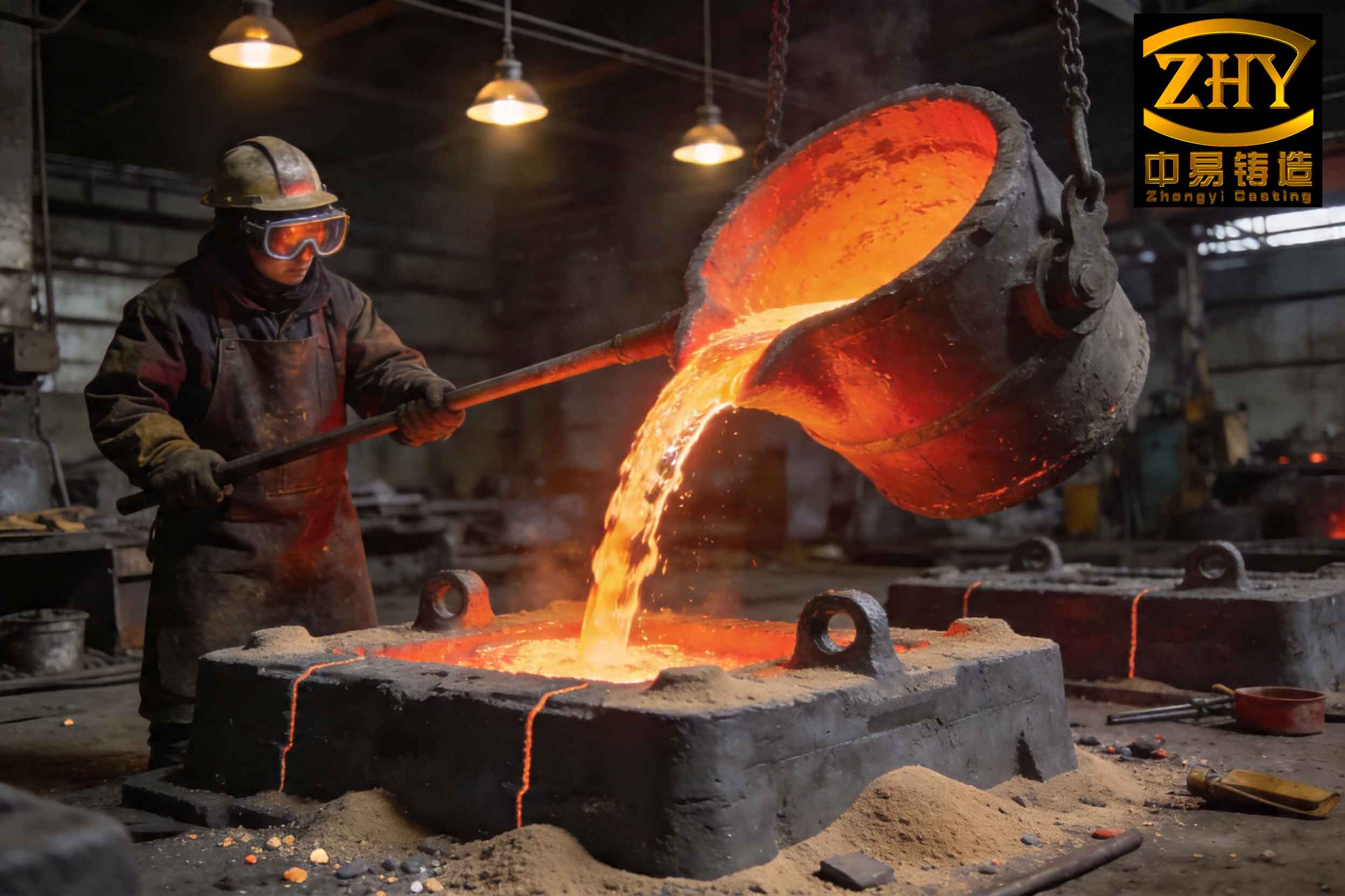
The formation of slag inclusions is multifaceted, involving factors such as foam model quality, coating integrity, sand handling, and process parameters. From my observations, the primary contributors include inadequate foam models with poor surface finish or density variations, weak or cracked coating layers that fail under thermal stress, improper assembly of model clusters leading to leakage points, and suboptimal pouring conditions that exacerbate turbulence. Understanding these causes is crucial for developing effective countermeasures. In the following sections, I will explore each aspect in detail, emphasizing how systematic control can reduce the incidence of slag inclusions.
To combat slag inclusions, a holistic approach encompassing material selection, process design, and operational diligence is essential. Based on my实践, I have identified several key areas where improvements yield significant results. First, the selection of white molds for both the casting and gating system is critical. The foam models must exhibit high surface smoothness and uniform density to prevent coating infiltration and subsequent detachment. Models with imperfections like small pits or sharp edges should be avoided or modified, as these can trap coating material that later dislodges during pouring. Preferably, gating system models should be fabricated from the same专用 material as the casting models, rather than cut from construction-grade foam boards, which have coarse, loosely fused grains that are prone to coating penetration and slag inclusion formation.
Second, the assembly of model clusters plays a pivotal role in preventing slag inclusions. Instead of coating individual components separately and assembling them in the mold box—a common practice that can leave weak joints—I recommend building an integrated model cluster by bonding the casting, gating, and any risers together before coating. This method creates a continuous, robust coating shell akin to the cavity in investment casting, which minimizes leakage points and enhances resistance to metal冲刷. Ensuring strong bonds at all interfaces is vital to maintain cluster integrity during handling and vibration.
Third, the coating layer serves as the primary barrier between the foam model and the molding sand. Its properties must include sufficient room-temperature strength to prevent cracking during drying and transport, as well as high thermal strength to withstand prolonged exposure to molten metal without spalling or erosion. The coating should be applied uniformly, with extra thickness on the gating system to bolster its冲刷 resistance. Care must be taken to avoid excessive buildup in internal corners, which can lead to cracking. Any gaps or seams should be sealed with foam repair paste before coating. The importance of coating quality cannot be overstated; most slag inclusions I have encountered originated from coating failures in the gating system, allowing sand and debris to infiltrate the metal stream.
Fourth, sand filling and molding operations require meticulous attention. The coated model cluster must be inspected for defects like cracks or bare spots before placement in the flask. It should be positioned steadily on the base sand to avoid悬空, which could cause coating damage during vibration. Initial sand addition should be gentle, followed by low-amplitude vibration until the model is fully embedded, then increased to achieve proper compaction. Throughout this process, avoiding direct冲击 on the model is key to preserving coating integrity. Additionally, the pouring cup must be cleaned thoroughly before浇注 to eliminate loose sand or contaminants that could introduce slag inclusions.
Fifth, casting process parameters must be optimized to minimize turbulence and thermal stress. Key factors include pouring head height, pouring temperature, vacuum level, and sand granularity. For example, excessive pouring height increases metal velocity and冲刷力, raising the risk of coating penetration and slag inclusion entrainment. Similarly, overly high pouring temperatures can degrade coating performance, while incorrect vacuum levels may exacerbate turbulence. To quantify these relationships, I often use empirical formulas to estimate the probability of slag inclusion formation. For instance, a simplified model for slag inclusion risk \( R \) can be expressed as:
$$ R = k_1 \cdot H^{a} + k_2 \cdot (T – T_0)^{b} + k_3 \cdot V^{c} + k_4 \cdot G^{d} $$
where \( H \) is the pouring head height, \( T \) is the pouring temperature, \( T_0 \) is a reference temperature, \( V \) is the vacuum level, \( G \) is the sand grain size, and \( k_1, k_2, k_3, k_4, a, b, c, d \) are constants derived from process data. This formula highlights how each parameter contributes to slag inclusion risk, emphasizing the need for balanced settings. In practice, I recommend the ranges shown in Table 1 for typical cast iron and high-chromium iron castings, which have proven effective in reducing slag inclusions.
| Parameter | Cast Iron | High-Chromium Iron |
|---|---|---|
| Pouring Temperature (°C) | 1380–1440 | 1480–1540 |
| Vacuum Level (MPa) | 0.025–0.040 | 0.030–0.045 |
| Sand Grain Size (Mesh) | 30/50 (Quartz) or 20/40 (Zircon) | 20/40 (Zircon recommended) |
| Pouring Head Height (mm) | Minimize, typically < 500 | Minimize, typically < 500 |
Moreover, the choice of molding sand significantly impacts slag inclusion occurrence. Zircon sand, with its rounded grains and high refractoriness, tends to reduce adhesion and improve flowability compared to angular quartz sand, thereby lowering the likelihood of sand ingress. The sand should be kept clean and free of fines through regular reclamation, as contaminants can nucleate slag inclusions. Table 2 summarizes best practices for sand management, which I have implemented to curb slag inclusion defects.
| Aspect | Best Practice | Impact on Slag Inclusions |
|---|---|---|
| Sand Type | Use rounded-grain sands like zircon | Reduces sand pickup and adhesion |
| Grain Size | Uniform distribution (e.g., 20/40 mesh) | Enhances compaction and minimizes voids |
| Cleanliness | Remove dust and debris via screening | Prevents impurity entrainment |
| Moisture Control | Keep dry (< 0.5% moisture) | Avoids gas evolution and turbulence |
In addition to these measures, statistical process control (SPC) can be employed to monitor and reduce slag inclusions. By tracking defect rates over time and correlating them with process variables, I have developed control charts that help identify deviations early. For example, the number of slag inclusions per batch \( N \) can be modeled using a Poisson distribution with mean \( \lambda \), where \( \lambda \) is a function of key parameters:
$$ \lambda = \exp(\beta_0 + \beta_1 H + \beta_2 T + \beta_3 V + \beta_4 G) $$
Here, \( \beta_0, \beta_1, \beta_2, \beta_3, \beta_4 \) are regression coefficients obtained from historical data. This approach allows for predictive adjustment of parameters to keep slag inclusion rates within acceptable limits. Furthermore, experimental designs such as response surface methodology (RSM) can optimize multiple factors simultaneously, as shown in Table 3 for a hypothetical experiment aimed at minimizing slag inclusions.
| Factor | Low Level | High Level | Optimal Point |
|---|---|---|---|
| Pouring Temperature (°C) | 1400 | 1500 | 1450 |
| Vacuum Level (MPa) | 0.020 | 0.050 | 0.035 |
| Coating Thickness (mm) | 0.5 | 1.5 | 1.0 |
| Vibration Time (s) | 30 | 90 | 60 |
The interplay between coating properties and process parameters is also critical. The coating’s thermal shock resistance can be quantified by its fracture toughness \( K_{IC} \) at elevated temperatures, which should exceed the stress induced by metal flow. A simple model for coating stress \( \sigma_c \) during pouring is:
$$ \sigma_c = \frac{E_c \alpha_c \Delta T}{1 – \nu_c} + \rho_m v^2 $$
where \( E_c \) is the coating’s Young’s modulus, \( \alpha_c \) is its thermal expansion coefficient, \( \Delta T \) is the temperature gradient, \( \nu_c \) is Poisson’s ratio, \( \rho_m \) is the metal density, and \( v \) is the metal velocity. To prevent coating failure and subsequent slag inclusions, \( \sigma_c \) must remain below \( K_{IC} \). This underscores the importance of selecting coatings with high thermal stability and adjusting pouring conditions to reduce mechanical and thermal loads.
Another often-overlooked aspect is the gating system design, which directly influences metal flow patterns and slag inclusion formation. I advocate for systems that promote laminar flow and include slag traps or filters. The Reynolds number \( Re \) for flow in the gating can be calculated as:
$$ Re = \frac{\rho_m v D_h}{\mu_m} $$
where \( D_h \) is the hydraulic diameter and \( \mu_m \) is the metal viscosity. Keeping \( Re \) below 2000 helps maintain laminar flow, reducing turbulence that can dislodge coating or entrain sand. Additionally, incorporating ceramic filters in the gating system can capture impurities, though their use must be balanced against cost and metal yield considerations.
Environmental and human factors also play a role in slag inclusion prevention. Training operators to handle models carefully, maintain equipment, and follow standardized procedures is essential. Regular audits of coating application, sand conditioning, and pouring practices can identify lapses that lead to slag inclusions. From my experience, a culture of continuous improvement, where every team member is vigilant about defect root causes, significantly reduces the incidence of slag inclusions over time.
In conclusion, slag inclusions in lost foam casting are a complex defect stemming from multiple sources, but they can be effectively managed through a systematic approach. By focusing on high-quality foam models, integrated cluster assembly, robust coatings, careful sand handling, and optimized process parameters, foundries can minimize the risk of sand and slag inclusions. The use of analytical tools like formulas and tables, as discussed, aids in quantifying and controlling these factors. Ultimately, success hinges on meticulous execution and ongoing monitoring, transforming lost foam casting into a reliable, high-yield process. As the industry evolves, further research into advanced coatings and real-time process control may offer even greater reductions in slag inclusion defects, paving the way for wider adoption of this versatile casting method.