
In our specialized foundry for producing ductile iron crankshafts, we consistently encounter the pervasive issue of slag inclusions. These slag inclusions severely compromise the impact toughness of castings, leading to reduced strength and wear resistance in crankshafts. Addressing slag inclusions is critical for ensuring product quality and reliability. While measures such as increasing pouring temperature, lowering residual magnesium content, and thorough slag skimming are essential, the design of the gating system plays a pivotal role in minimizing slag inclusions. Through extensive practical experience, we have conducted comparative studies on three distinct gating system configurations to evaluate their effectiveness in reducing slag inclusions. This article details our findings, supported by analytical tables and formulas, to provide a comprehensive guide for optimizing gating systems in ductile iron casting.
Slag inclusions, often referred to as dross or oxide inclusions, are non-metallic compounds entrapped within the metal matrix during the pouring and solidification processes. In ductile iron, these slag inclusions primarily originate from oxidized magnesium and other reactive elements, forming complex oxides and sulfides. The presence of slag inclusions not only deteriorates mechanical properties but also serves as stress concentrators, potentially leading to catastrophic failures in dynamic applications like crankshafts. Therefore, developing robust methods to control slag inclusions is paramount. Our approach focuses on modifying the gating system to alter fluid dynamics, thereby reducing turbulence and enhancing slag capture before the metal enters the mold cavity.
We investigated three gating system designs: a fully pressurized (closed) system, a semi-pressurized system without a slag trap, and a semi-pressurized system incorporating a slag trap with a ceramic filter. The geometric parameters are summarized in Table 1. The fully pressurized system features a constricted cross-sectional area at the ingates, promoting high velocity but increased turbulence. In contrast, the semi-pressurized systems have larger cross-sectional areas in the runner, slowing down the flow and promoting laminar conditions. The inclusion of a slag trap and filter further enhances slag removal by providing a calm zone and physical filtration.
| Gating System Type | Downsprue Area (cm²) | Runner Area (cm²) | Ingate Area (cm²) | Additional Features |
|---|---|---|---|---|
| Closed (Pressurized) | 12.6 | 9.6 | 7.1 | None |
| Semi-pressurized (No Slag Trap) | 12.6 | 15.9 | 7.1 | None |
| Semi-pressurized (With Slag Trap) | 12.6 | 15.9 | 7.1 | Slag trap with ceramic filter (outer diameter 50 mm, 36 holes of Ø3 mm) |
Our experiments were conducted on Yuchai 6102 diesel engine crankshafts. Each mold produced two castings, with a individual casting weight of approximately 38 kg. We meticulously controlled process variables: pouring temperature was maintained between 1,350°C and 1,370°C using thermocouples, and the pouring time for each mold was consistently 22-26 seconds. All other production parameters—including melting practice, mold material, and alloy composition—were held constant to isolate the effect of the gating system. Post-casting, we employed dry magnetic particle inspection, visual examination, and sulfur printing to detect and characterize slag inclusions. The criteria for rejection were based on the size, thickness, and distribution of slag inclusions, which directly affect mechanical performance.
| Aspect | Details |
|---|---|
| Casting | Yuchai 6102 Diesel Engine Crankshaft |
| Casting Weight per Piece | ~38 kg |
| Pouring Temperature | 1350°C – 1370°C |
| Pouring Time per Mold | 22-26 seconds |
| Slag Inclusion Detection Methods | Dry Magnetic Particle Inspection, Visual Inspection, Sulfur Printing |
| Key Variable | Gating System Design |
The results unequivocally demonstrated the superiority of certain gating designs in controlling slag inclusions. Table 3 quantifies the rejection rates and qualitative observations for each system. The closed gating system yielded castings with a medium-thickness layer of slag inclusions and medium-sized spot slag, leading to a rejection rate of about 6%. The semi-pressurized system without a slag trap showed a thinner layer of slag inclusions and very few spot slag particles, reducing the rejection rate to approximately 4%. The best performance was achieved with the semi-pressurized system equipped with a slag trap and ceramic filter, which produced castings with a very thin layer of slag inclusions, minimal spot slag, and a rejection rate below 1%. These findings highlight the progressive improvement in mitigating slag inclusions through systematic gating design modifications.
| Gating System Type | Characteristics of Slag Inclusions | Rejection Rate Due to Slag Inclusions | Overall Anti-Slag Effectiveness |
|---|---|---|---|
| Closed (Pressurized) | Medium-thickness layer, medium-sized spot slag inclusions | ~6% | Poor |
| Semi-pressurized (No Slag Trap) | Thin layer, very few spot slag inclusions | ~4% | Good |
| Semi-pressurized (With Slag Trap & Filter) | Very thin layer, extremely few spot slag inclusions | <1% | Excellent |
To understand these outcomes, we delve into fluid dynamics principles governing molten metal flow in gating systems. The primary goal is to reduce flow velocity and turbulence, as high kinetic energy promotes reoxidation and entrains existing slag inclusions. The velocity in a channel is given by the continuity equation:
$$v = \frac{Q}{A}$$
where \( v \) is the flow velocity, \( Q \) is the volumetric flow rate, and \( A \) is the cross-sectional area. In a closed gating system, the ingate area is smaller than the runner area, causing acceleration and high velocity at the ingates, which increases turbulence. The Reynolds number (\( Re \)) indicates the flow regime:
$$Re = \frac{\rho v D_h}{\mu}$$
where \( \rho \) is density, \( D_h \) is hydraulic diameter, and \( \mu \) is dynamic viscosity. Higher \( Re \) values signify turbulent flow, which is detrimental as it enhances slag inclusion formation and transport. For the semi-pressurized system, the runner area is significantly larger, reducing \( v \) and consequently \( Re \), promoting more laminar flow. This reduces the kinetic energy available for reoxidation and allows slag particles to separate by buoyancy or be captured by the runner walls.
The inclusion of a slag trap with a ceramic filter further optimizes this process. The slag trap acts as a low-velocity zone where slag inclusions can float to the surface due to density differences. The ceramic filter, with its multiple small-diameter channels, performs two critical functions: it reduces flow velocity through increased flow resistance, and it physically traps slag inclusions larger than the pore size. The pressure drop across the filter can be approximated using the Darcy-Forchheimer equation for porous media:
$$\Delta P = \frac{\mu L}{K} v + \beta \rho v^2$$
where \( \Delta P \) is pressure drop, \( L \) is filter thickness, \( K \) is permeability, and \( \beta \) is the inertial resistance coefficient. This pressure drop dampens flow fluctuations, minimizing turbulence downstream. Moreover, the filter’s design promotes a quiescent flow, reducing the tendency for new slag inclusions to form. The effectiveness of slag inclusion removal can be modeled as a capture efficiency \( \eta \), which increases with decreased velocity and increased residence time in the slag trap.
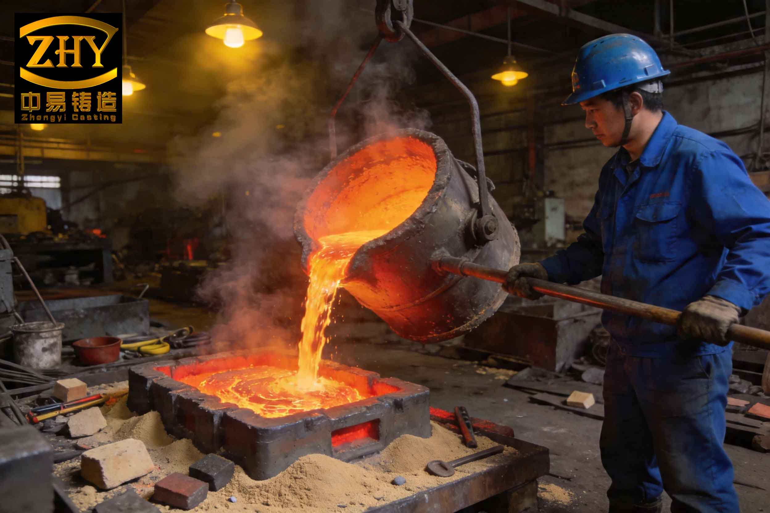
Beyond the gating system, other factors influence slag inclusion formation. Pouring temperature is critical; lower temperatures increase viscosity, hindering slag separation, while excessively high temperatures can accelerate oxidation. We maintain a narrow range of 1350-1370°C to balance fluidity and oxidation kinetics. Residual magnesium content is another key variable; high residual magnesium increases the propensity for magnesium oxide slag inclusions. We aim for minimal residual magnesium through precise inoculation and treatment practices. Additionally, proper ladle management, such as using covered ladles and argon purging, can reduce slag generation before pouring. However, even with these controls, the gating system remains the last line of defense against slag inclusions entering the casting.
Our empirical data aligns with theoretical predictions. The semi-pressurized system reduces velocity in the runner by approximately 40% compared to the closed system, calculated from the area ratios. This reduction directly correlates with lower turbulence and fewer slag inclusions. The filter-equipped system adds another layer of protection, capturing slag inclusions that escape the runner. We observed that the size distribution of slag inclusions shifted toward smaller, less detrimental particles with improved gating designs. Statistical analysis of defect maps revealed that slag inclusions were predominantly located near the ingates in the closed system, while in the filter-equipped system, they were almost absent in critical stress areas of the crankshaft.
To generalize these findings, we propose a comprehensive framework for gating system design to minimize slag inclusions. The principles include: (1) maximizing runner cross-sectional area to reduce flow velocity, (2) incorporating slag traps or expansion chambers to promote buoyant separation, (3) using filters to physically remove slag inclusions, and (4) ensuring smooth transitions to avoid flow separation and vortex formation. The optimal area ratios can be derived from Bernoulli’s principle and energy conservation considerations. For ductile iron, we recommend a semi-pressurized system with a runner-to-ingate area ratio greater than 1.5 and a well-designed slag trap. The filter should be selected based on pore size (typically 3-5 mm for general applications) and permeability to balance filtration efficiency and flow rate.
In practice, implementing these designs requires careful pattern-making and mold assembly. We have standardized the use of ceramic filters in our production, placing them in the slag trap at the end of the runner. The filter orientation and seating are crucial to prevent bypass and ensure uniform flow. Regular monitoring of filter condition and replacement is essential to maintain consistency. Furthermore, we conduct periodic fluid dynamics simulations using software like FLOW-3D to optimize gating geometries before physical trials, reducing development time and cost. These simulations help visualize flow patterns and predict areas prone to slag inclusion formation.
The economic impact of reducing slag inclusions is substantial. Lower rejection rates directly translate to higher yield and reduced scrap handling costs. For our annual production volume, decreasing the slag inclusion rejection rate from 6% to below 1% saves significant material and energy resources. Moreover, improved product quality enhances customer satisfaction and market competitiveness. Therefore, investing in optimized gating systems is not only a technical necessity but also a strategic business decision. We continue to refine our processes, exploring advanced filter materials and automated pouring systems to further mitigate slag inclusions.
In conclusion, our experience demonstrates that slag inclusions in ductile iron crankshafts can be effectively controlled through rational gating system design. The semi-pressurized gating system with a slag trap and ceramic filter outperforms both closed and simple semi-pressurized systems, achieving rejection rates below 1%. This superiority stems from reduced flow velocity, minimized turbulence, and enhanced physical filtration, all of which limit the formation and entrapment of slag inclusions. By integrating fluid dynamics principles with practical foundry engineering, we have established a robust methodology for producing high-integrity castings. We encourage other foundries to adopt similar approaches, tailoring designs to their specific alloys and casting geometries, to combat the persistent challenge of slag inclusions and elevate overall casting quality.