
In my extensive career dedicated to advanced casting processes, lost foam casting has always stood out as a revolutionary method, promising exceptional dimensional accuracy and surface finish. However, its adoption is not without significant challenges. Among the most persistent and economically damaging issues I have confronted is the slag inclusion defect. This defect, manifesting as embedded sand particles or non-metallic inclusions within the cast metal, can severely compromise the integrity and machinability of components, particularly those for automotive applications. Through this article, I will share a comprehensive, first-hand analysis of the slag inclusion defect, weaving in theoretical foundations, practical observations, and systematic countermeasures. The goal is to provide a holistic understanding that extends beyond simple guidelines to a deeper engineering comprehension.
The slag inclusion defect is not merely a surface anomaly. When a casting is machined, these defects appear as distinct white or greyish-black spots. The white spots are typically silica sand grains, while the darker ones are complex aggregates of degraded coating material, carbonaceous residues from the foam pyrolysis, and other oxides. This slag inclusion defect often originates long before the metal solidifies. A telltale sign during shakeout is excessive burn-on or cracking-type sand adhesion on the gating system surfaces. If the sprue or runner breaks to reveal a ring of white specks, it is a clear indicator of systemic sand penetration. The financial impact is substantial, leading to high scrap rates and delayed deliveries for precision parts like clutch plates and engine covers.
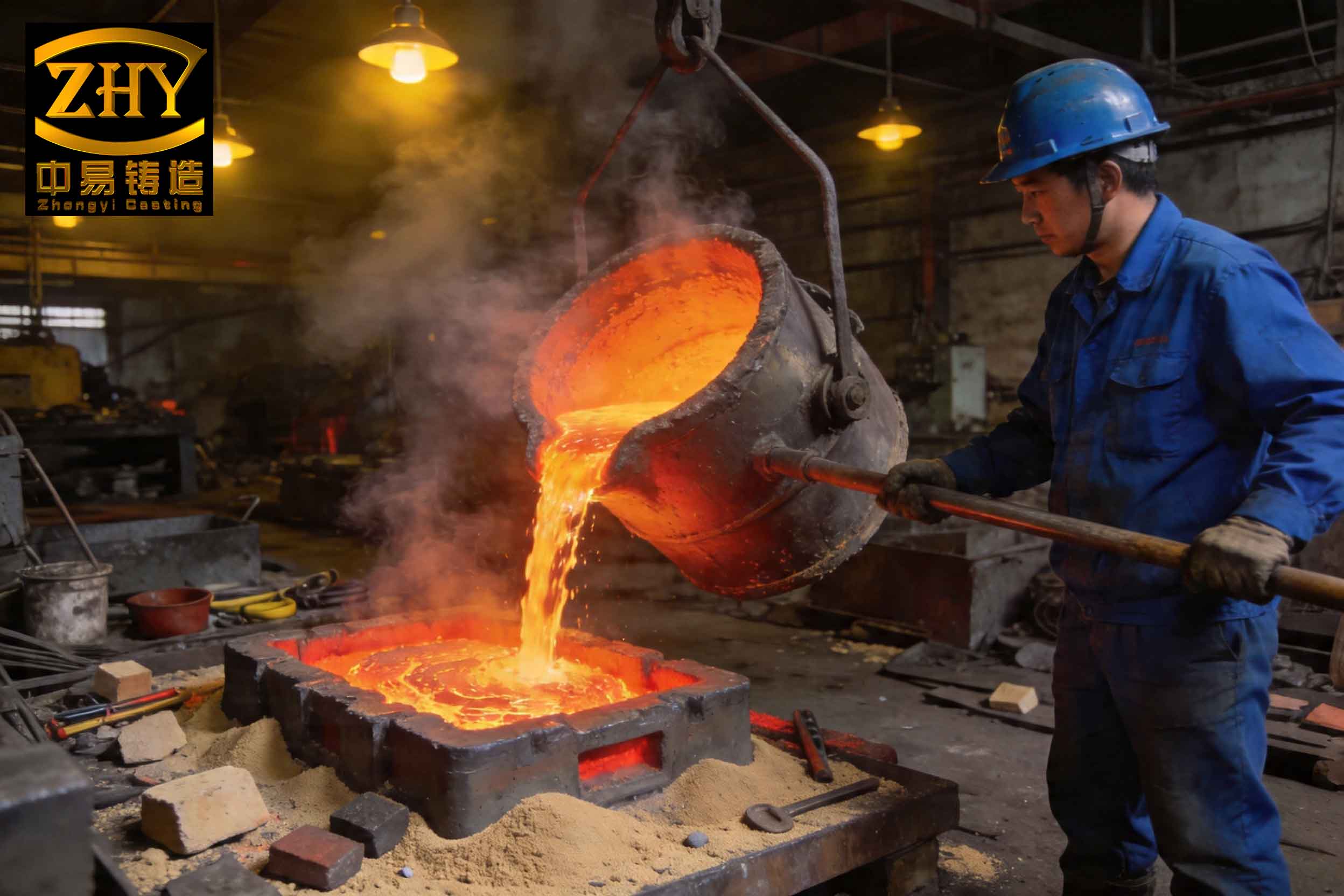
Understanding the genesis of a slag inclusion defect requires a multi-factorial failure mode analysis. From my experience, the primary failure path involves the breach of the protective coating layer. The coating acts as the critical barrier between the molten metal and the unbonded sand mold. Its failure, in any form, is an invitation for a slag inclusion defect. The causes can be systematically categorized as follows.
Coating-Related Causes: The coating must survive two critical phases: the drying/handling phase and the metal pouring phase. Insufficient dry strength leads to cracking during transport or mold filling. During pouring, the coating experiences severe thermomechanical stress. The sudden heat flux causes rapid thermal expansion. If the coating’s thermal shock resistance or hot strength is inadequate, it will spall, crack, or even liquefy. The mechanical erosion from high-velocity metal flow exacerbates this. The coating’s performance can be modeled by considering the thermal stress at the metal-coating interface. The induced stress ($\sigma_t$) can be approximated by:
$$\sigma_t = E_c \cdot \alpha_c \cdot \Delta T$$
where $E_c$ is the coating’s elastic modulus at elevated temperature, $\alpha_c$ is its coefficient of thermal expansion, and $\Delta T$ is the instantaneous temperature difference upon metal impact. A high $\sigma_t$ exceeding the coating’s cohesive strength directly causes cracking, creating pathways for sand ingress and initiating a slag inclusion defect.
Process Operation Causes: Even a perfect coating can be compromised by suboptimal operations. Rough handling of foam patterns, improper assembly of gating systems (leaving gaps or weak joints), and aggressive sand filling can mechanically damage the coating. In vacuum-assisted casting, an excessively high negative pressure can literally suck sand particles through microscopic coating cracks. The fluid dynamics of sand during vibration also plays a role. The drag force ($F_d$) on a coating protrusion or a vulnerable joint during sand fluidization can be described as:
$$F_d = \frac{1}{2} C_d \cdot \rho_s \cdot A \cdot v_s^2$$
where $C_d$ is the drag coefficient, $\rho_s$ is the apparent density of the fluidized sand, $A$ is the projected area, and $v_s$ is the relative sand velocity. High $F_d$ can peel off coating layers.
Gating and Pouring Parameters: The hydraulic characteristics of the pour are pivotal. A high metallostatic head increases the dynamic pressure and velocity of the metal, enhancing its scouring power. The Bernoulli principle explains this: $P + \frac{1}{2}\rho_m v^2 + \rho_m gh = constant$. A larger height $h$ translates to higher velocity $v$ at the gates, increasing the shear stress on the coating. Pouring temperature is a double-edged sword; while necessary for fluidity, an excessively high temperature accelerates coating degradation and metal penetration. The rate of heat transfer ($q”$) into the coating governs its stability: $q” = h_c (T_m – T_c)$, where $h_c$ is the heat transfer coefficient, $T_m$ is the metal temperature, and $T_c$ is the coating surface temperature. Higher $T_m$ drastically increases $q”$, pushing the coating towards its failure limit.
The following table summarizes the root causes and their mechanisms leading to the slag inclusion defect.
| Category | Specific Cause | Mechanism Leading to Slag Inclusion Defect |
|---|---|---|
| Coating | Low Dry Strength | Cracking during handling/vibration exposes foam, leading to sand adhesion and subsequent entrainment. |
| Low Hot Strength / Refractoriness | Softening, erosion, or melting under metal flow, allowing direct sand/metal contact. | |
| Poor Thermal Shock Resistance | Cracking due to rapid heating, creating open channels for sand infiltration. | |
| Operation | Improper Pattern Assembly | Gaps at glued joints become sand traps; weak connections fail under sand pressure. |
| Aggressive Sand Filling/Vibration | Mechanical impact and abrasion damage coating integrity, especially on edges. | |
| Inadequate Sprue Seal | Sand falls directly into the pouring stream, causing immediate and severe slag inclusion defect. | |
| High Vacuum Pressure | Increased pressure differential forces sand particles into any coating discontinuity. | |
| Process Parameters | High Pouring Height | Increased metal velocity and turbulence erodes coating and entrains loose material. |
| Inappropriate Pouring Temperature | High temp degrades coating; low temp increases viscosity, trapping inclusions. | |
| Slow Pouring Time | Prolonged exposure of coating to hot metal increases chances of thermal failure. | |
| Materials | Coarse Sand Grain Size | Larger sand grains are more easily entrapped and are more difficult to filter out by coating cracks. |
Combating the slag inclusion defect is a holistic endeavor requiring simultaneous optimization across materials, process, and design. Based on my trials and implementations, the following integrated approach has proven effective.
1. Advanced Coating Engineering: The coating is the first line of defense. We must engineer it for multifunctional performance. A robust coating formulation balances antagonistic properties: strength versus permeability, refractoriness versus thermal shock resistance. I specify coatings with a high-temperature binder system (e.g., colloidal silica reinforced with refractory fillers like zircon, alumina, or fused silica). The coating thickness is critical; it must be sufficient to withstand abrasion but not so thick as to hinder gas evacuation or cause cracking during drying. I often use a dual-coating strategy: a finer, stronger primary coat on the pattern and a more refractory, slightly permeable backup coat. The adhesion strength ($\tau_{adh}$) can be conceptually related to the binder’s performance: $\tau_{adh} \propto \frac{S_b \cdot \phi}{d_p}$, where $S_b$ is the binder strength, $\phi$ is the binder volume fraction, and $d_p$ is the refractory particle size. Optimizing this ratio is key.
2. Meticulous Pattern and Mold Preparation: Discipline in the foam room and molding station is non-negotiable. All pattern assembly joints must be smooth, fully sealed with adhesive, and reinforced with clay or extra coating at critical junctions like sprue-to-runner connections. I insist on applying a seal coat over these joints. During mold filling, a soft rain sand system is used initially to gently encapsulate the pattern. Vibration parameters—amplitude, frequency, and time—are strictly controlled. We start with low amplitude to settle sand without imparting excessive kinetic energy to the pattern. The following table outlines a optimized vibration regime to minimize coating damage.
| Molding Stage | Amplitude (mm) | Frequency (Hz) | Duration (s) | Objective |
|---|---|---|---|---|
| Initial Fill | 0.2 – 0.5 | 30 – 40 | 10 – 20 | Gentle sand settling without pattern displacement. |
| Main Compaction | 0.5 – 1.0 | 50 – 60 | 30 – 60 | Achieve uniform and high bulk density around pattern. |
| Final Settling | 0.2 – 0.5 | 30 – 40 | 5 – 10 | Relieve locked-in stresses in sand without re-fluidizing. |
3. Optimized Pouring Practice and Gating Design: The pouring ritual is where theory meets practice. I use ladles with snuggly fitting nozzles to control stream size and minimize height. The ideal pouring height ($H_{opt}$) balances mold filling time against erosion potential. An empirical relation I’ve found useful for iron alloys is: $H_{opt} (mm) \approx k \cdot \sqrt[3]{W}$, where $W$ is the casting weight in kg and $k$ is a constant between 20-30 for gray iron. Pouring temperature is carefully selected; for typical gray iron castings, I target 1380-1420°C. The pouring time ($t_p$) is synchronized with the vacuum draw to ensure a calm, progressive fill. A key design modification is incorporating slag traps. A whirlgate or a dam in the runner system can be highly effective. The principle uses centrifugal force: inclusions with density $\rho_i$ different from the metal $\rho_m$ are separated. The trajectory of an inclusion particle in a curved runner can be modeled, and the separation efficiency is enhanced by controlling the radius of curvature ($R$) and flow velocity ($v$).
4. Precise Vacuum and Thermal Management: Vacuum is a powerful but delicate tool. For铸铁, I maintain a vacuum level in the range of 0.025 to 0.04 MPa (≈ 190 to 300 mmHg). A vacuum that is too high not only increases sand suction risks but also accelerates foam pyrolysis, potentially overloading the coating with gaseous products and causing back-pressure or coating rupture. The gas evolution rate from the foam ($\dot{G}$) must be matched by the evacuation capacity of the coating and sand ($Q_{vac}$). A simplified mass balance is: $\dot{G} = A_p \cdot r_p \cdot \rho_f \cdot Y_g$ should be less than $Q_{vac} = K \cdot A_c \cdot (P_{sys} – P_{atm}) / \mu$, where $A_p$ is pattern area, $r_p$ is pyrolysis rate, $\rho_f$ is foam density, $Y_g$ is gas yield, $K$ is coating permeability, $A_c$ is coating area, $P_{sys}$ is system pressure, and $\mu$ is gas viscosity. Managing this balance prevents pressure buildup that can burst the coating.
5. Metal Treatment and Filtration: Ultimately, some inclusions may be generated from the metal itself or from broken coating fragments. Therefore, in-mold filtration is my last line of defense against the slag inclusion defect. I place ceramic foam filters at strategic points in the gating system, typically in the downsprue or at the entrance to the runner. The filter efficiency for capturing particles larger than a critical size ($d_c$) can be described by a sieve model combined with deep-bed filtration mechanics. The pressure drop ($\Delta P_f$) across the filter must be accounted for in the gating design: $\Delta P_f \approx \frac{\mu v t_f}{k_f}$, where $\mu$ is metal viscosity, $v$ is approach velocity, $t_f$ is filter thickness, and $k_f$ is filter permeability. Properly sized, a filter can drastically reduce the frequency and severity of the slag inclusion defect.
The interplay of all these factors dictates the final casting quality. To guide process selection, I have developed a decision matrix that correlates key controllable variables with the probability of a slag inclusion defect. This matrix, born from statistical process control data, helps in troubleshooting and preventive action.
| Process Variable | Low/Inadequate Setting | Optimal Range | High/Excessive Setting | Impact on Slag Inclusion Defect Risk |
|---|---|---|---|---|
| Coating Hot Strength (MPa at 1200°C) | < 0.5 | 1.0 – 2.0 | > 3.0 (may crack) | High risk at low strength; moderate risk at very high due to brittleness. |
| Pouring Temperature (°C) for Gray Iron | < 1350 | 1380 – 1420 | > 1450 | High risk at low temp (cold shuts trap slag); Very High risk at high temp (coating erosion). |
| Vacuum Pressure (MPa) | < 0.015 (incomplete fill) | 0.025 – 0.04 | > 0.05 | Moderate risk at low vacuum; High risk at high vacuum (sand suction). |
| Sand Grain Size (AFS GFN) | < 40 (coarse) | 50 – 70 | > 80 (fine) | High risk with coarse sand; Moderate risk with very fine sand (low permeability). |
| Pattern Coating Thickness (mm) | < 0.5 | 0.8 – 1.5 | > 2.0 | High risk if too thin; High risk if too thick (cracking, poor degassing). |
In conclusion, eradicating the slag inclusion defect in lost foam casting is an exercise in systems thinking. It demands a synergistic approach where materials science, fluid dynamics, thermal management, and rigorous procedural control converge. There is no single magic bullet. From my journey, success hinges on treating the coating as a engineered ceramic shell, the molding process as a precise vibration-dynamics problem, and the pouring practice as a controlled hydraulic event. Each step, from pattern gluing to ladle tilt, must be executed with an awareness of its potential to create or prevent a slag inclusion defect. The implementation of filtering technology and intelligent gating design provides a robust safety net. By embracing this comprehensive philosophy, foundries can transform the challenge of the slag inclusion defect from a frequent failure into a rare exception, fully harnessing the potential of the lost foam process for producing high-integrity, near-net-shape castings. The battle against the slag inclusion defect is won not in the furnace or the pouring aisle alone, but in the meticulous attention to detail across the entire value stream.