
As a foundry engineer who has spent over a decade working in the sand casting industry, I have witnessed firsthand the many challenges that traditional molding processes face. The industry has long struggled with high labor intensity, poor working environments, and the heavy burden of tooling costs for small-batch production. In recent years, the emergence of additive manufacturing, particularly 3d sand printing, has completely changed the way we think about producing sand molds and cores. In this article, I would like to share my perspective on the application prospects of 3d sand printing in the field of sand casting, based on our practical experience and ongoing research.
The core principle of 3d sand printing is to build sand molds layer by layer directly from a digital model, without any physical pattern or core box. This technology, also known as binder jetting, deposits a thin layer of sand and selectively applies a binder according to the cross-section data. After repeated layering and curing, a complete sand mold or core is formed. The entire process is automated, dust-free, and remarkably flexible. For foundries like ours that handle a wide variety of complex components, 3d sand printing has become an indispensable tool for rapid prototyping and small-series production.
Challenges Faced by Conventional Sand Casting
Before discussing the benefits of 3d sand printing, it is important to understand the problems that have plagued traditional sand casting for decades. These problems are not new, but they have become increasingly acute as market demands shift toward customization and shorter lead times.
Self-Development Bottlenecks
Casting is an irreplaceable basic industry that supports everything from aerospace to automotive to construction machinery. However, the conventional foundry environment is often characterized by high temperatures, noise, dust, and heavy physical labor. Many young workers are reluctant to enter this industry, leading to a serious shortage of skilled labor in foundries across China and elsewhere. We are constantly challenged with recruiting and retaining employees. The root cause is the outdated working environment. To attract the next generation, we must drastically improve working conditions. 3d sand printing offers a clean, automated alternative that isolates the operator from harmful dust and fumes. By implementing 3d sand printing cells, we can shift workers from manual sand ramming and shakeout to supervisory roles in a clean control room, which directly addresses the labor crisis.
Product Structure Shifts
Another major challenge is the changing product structure. In the past, mass production of identical parts was the norm. Today, customization is the mainstream. Our clients frequently order single pieces or very small batches, and each order may be unique. Traditional mold-based casting cannot economically accommodate such high variety. Indeed, the cost of a metal pattern can range anywhere from ¥200,000 to ¥500,000, and the manufacturing lead time can be two months or more. When the project ends, these patterns become idle assets that consume warehouse space and require maintenance. 3d sand printing completely eliminates the need for physical patterns, since the mold geometry is stored as a digital file. When a product is no longer needed, we simply delete the file, leaving no physical inventory. This aligns perfectly with the lean and flexible manufacturing model that modern enterprises must adopt.
Environmental Regulations
Environmental protection is another pressing issue. Casting has been listed as a heavily polluting industry in many regions. Traditional sand mixing, core making, and shakeout operations release dust, volatile organic compounds, and noise. Conventional pollution control measures like dust collectors and scrubbers are end-of-pipe solutions, which are expensive and not always effective. 3d sand printing, however, is a clean process by design. Since the sand and binder are handled inside a sealed chamber, dust emissions are minimal. The binder is consumed during printing, so there is little waste. Moreover, unused sand can be recycled, further reducing the environmental burden. Therefore, 3d sand printing is not just a convenience, but a strategic response to stricter environmental regulations.
Advantages of 3D Sand Printing
Based on my experience operating industrial 3d sand printing equipment, I have identified six major advantages that this technology brings to sand casting:
- Process simplification: The molding and core-making processes are integrated into a single printing step. We no longer need pattern making, core box manufacturing, sand molding lines, or core assembly fixtures for the initial sample.
- Reduced labor intensity: Printing is fully automated and contained. Workers do not touch sand or binder directly, dramatically improving workplace ergonomics.
- Higher dimensional accuracy: 3D printed sand molds have a typical dimensional tolerance of ±0.3 mm per 100 mm, much better than hand-molded or conventionally machine-molded sands. This allows us to reduce machining allowances and improve as-cast quality.
- Design freedom: Undercuts, internal cooling channels, and complex curved surfaces can be printed without any draft angle. In conventional casting, the pattern must be withdrawn from the mold, forcing designers to add draft angles. With 3d sand printing, there is no such constraint, enabling truly optimized designs.
- Rapid iteration: If the casting design changes during development, we only need to modify the CAD model and reprint. This reduces the iteration cycle from weeks to days or even hours.
- Low tooling cost: For single-piece or small-batch production, the cost of 3d sand printing is often lower than the combined cost of pattern material, machining, and maintenance. The break-even point compared with conventional pattern casting typically lies between 50 and 200 pieces, depending on complexity.
To summarize these advantages, I have compiled a comparison table between conventional molding and 3d sand printing:
| Aspect | Conventional Sand Molding | 3D Sand Printing |
|---|---|---|
| Pattern/core box required | Yes | No |
| Lead time for first part | 4–12 weeks (pattern making) | 1–3 days (model + printing) |
| Tooling cost for low volume | High | Negligible |
| Dimensional accuracy | ±0.5–1.0 mm | ±0.2–0.4 mm |
| Draft angle requirement | Usually 1–3 degrees | None |
| Minimum wall thickness | 3–5 mm (depending on sand) | 2–3 mm |
| Worker exposure to dust | High | Minimal |
| Design change cost | High (new pattern) | Low (reprint) |
| Ideal batch size | > 1000 pieces | 1–200 pieces |
This table clearly shows that 3d sand printing is not intended to replace high-volume production, but rather to fill the gap of complex, high-value, low-volume castings.
Practical Applications of 3D Sand Printing
I have personally led several projects that used 3d sand printing to solve real industrial problems. The following case studies illustrate the versatility and efficiency of this technology in different domains.
Automotive Steering Gear Components
The first application is a steering gear housing for passenger cars. The casting has a complex internal geometry with multiple machined bores and mounting bosses. In the conventional process, we used investment casting to produce this component, which required a lengthy sequence: wax injection, pattern assembly, shell building with multiple ceramic dips, dewaxing, firing, pouring, and knockout. The shell-making alone needed three to five repeated coating cycles, causing a production cycle of up to two months. During product development, the design changed many times, and each change meant new wax dies, which was very costly.
With 3d sand printing, we directly printed the sand mold and core from the CAD file. The process was streamlined to: design review, sand printing, assembly, pouring, and finishing. The first castings were available within five working days. More importantly, every design revision only required reprinting the affected sand cores, which took less than a day. The savings were enormous: we reduced the development cost by about 70% and cut the lead time by 80%. The casting quality also improved because the mold cavities had a smoother surface finish and tighter dimensional consistency, minimizing the need for correction.
Engine Components
Another project involved a cylinder head for a high-performance diesel engine. This component has very tight tolerance requirements (CT8 or better) and numerous internal coolant passages and valve seats. Traditionally, we would machine a metal pattern and use hot-box core shooting to produce the complex sand cores. The metal pattern tooling cost for such a part was between ¥500,000 and ¥1,000,000, and the lead time was eight to ten weeks. Any modification to the core design would require rebuilding the entire tool, which is extremely expensive and slow.
By using 3d sand printing, we produced all the cores in a single build, without any tooling. The dimensional accuracy of the printed cores was excellent, and the design flexibility allowed us to optimize the wall thickness distribution and improve cooling performance. The new cylinder head passed the engine test on the first attempt, a remarkable achievement in our company. Based on this success, we have adopted a hybrid approach: for the first 100 prototypes, we use 3d sand printing; only after the design is fully validated do we invest in production tooling for mass production. This strategy significantly reduces the risk of costly tooling revisions and accelerates the time to market.
Electric Motor Housings
Thirdly, we used 3d sand printing to manufacture motor housings with very dense cooling fins. Such housings can have between 40 and 100 fins, each with a depth of 100 to 120 mm, length between 100 and 1,800 mm, thickness 4 to 8 mm, and a gap between fins of only 5 to 6 mm. In conventional sand casting, every fin has to be machined as a separate pattern insert because it is impossible to withdraw the pattern from the sand without breaking the thin fins. Assembling and disassembling 50 to 100 inserts is labor-intensive and prone to damage, often destroying the entire mold.
3d sand printing enables us to print the entire mold cavity, including all fins, in one piece. Since there is no pattern withdrawal, the fins can be printed vertically, horizontally, or at any angle. The resulting accuracy of the fin pitch and thickness is exceptional. We have produced as many as 80 fins in a single printing job with zero defects. This would have been unthinkable using traditional methods. The application of 3d sand printing has therefore opened new design possibilities for motor housings with increased surface area and better heat dissipation.
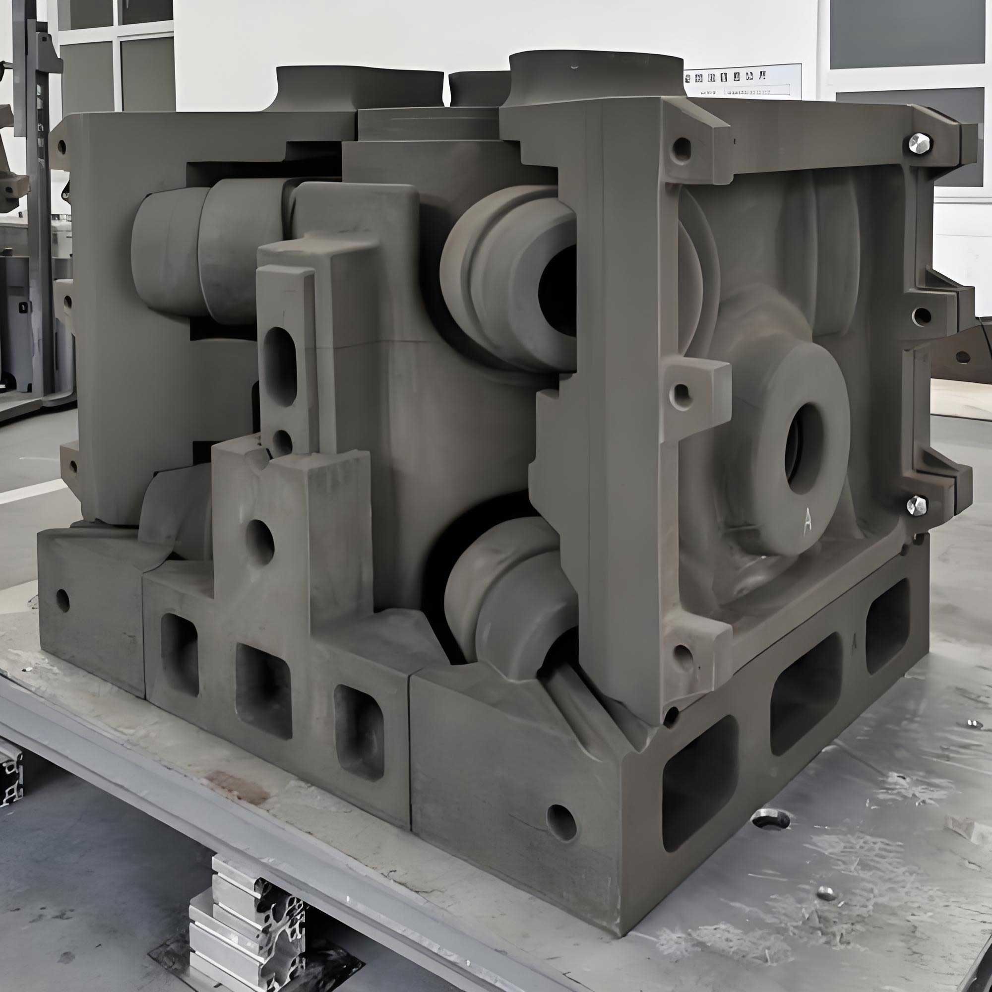
Here is an illustrative image from our facility showing a typical 3d sand printing setup and printed molds:
Economic Analysis of 3D Sand Printing
To quantitatively assess the economics of 3d sand printing, I have developed a simplified cost model. The total cost per casting, \(C_p\), can be expressed as the sum of tooling cost amortized per part, printing cost per part, and post-processing cost:
$$C_p = \frac{C_{tool}}{N} + C_{print} + C_{post}$$
where:
– \(C_{tool}\) is the total cost of pattern or tooling. For 3d sand printing, \(C_{tool} \approx 0\).
– \(N\) is the total quantity produced.
– \(C_{print}\) is the cost of sand, binder, and machine time per part.
– \(C_{post}\) includes cleaning, coating, assembly, and finishing.
For conventional casting, \(C_{tool}\) is high and must be divided by \(N\). Therefore, for small \(N\), the conventional cost is dominated by \(C_{tool}/N\), which tends to be massive. In contrast, 3d sand printing has no tooling cost and a constant \(C_{print}\) regardless of quantity.
The table below presents an illustrative cost comparison for a steering gear housing (34 kg) using both methods for 20 prototype pieces, based on data from our actual projects:
| Cost item (per piece) | Investment Casting (conventional) | 3D Sand Printing |
|---|---|---|
| Tooling amortization | ¥15,000 (total pattern ¥300,000 / 20) | ¥0 |
| Pattern maintenance | ¥2,000 | ¥0 |
| Mold/shell material | ¥1,500 | ¥2,800 (sand + binder) |
| Direct labor | ¥3,200 | ¥800 |
| Machine amortization (printing) | ¥0 | ¥1,200 |
| Post-processing | ¥1,000 | ¥1,000 |
| Total per piece | ¥22,700 | ¥5,800 |
| Total for 20 pieces | ¥454,000 | ¥116,000 |
This table demonstrates that for low-volume and prototyping, 3d sand printing is not only faster but also significantly cheaper. Even when including the initial investment in the printer, which is a fixed asset, the payback period can be acceptable given enough prototype projects.
Moreover, we must account for the value of time. The total time to first article, \(T\), can be modeled as:
$$T = T_{tool} + T_{mold} + T_{pour} + T_{post}$$
For conventional casting, \(T_{tool}\) is often weeks or months, whereas for 3d sand printing, \(T_{tool}=0\). The direct saving in lead time is proportional to the reduction in \(T\), which can be expressed as a financial benefit, \(B_{time} = v_{time} \times \Delta T\), where \(v_{time}\) is the opportunity cost per day. In our automotive development projects, a day saved is worth approximately ¥10,000, so reducing lead time by 40 days yields ¥400,000 value, exceeding the printing cost.
Technical Considerations for Successful 3D Sand Printing
Despite its advantages, 3d sand printing is not a panacea. To achieve high-quality molds and cores, we must carefully control several parameters. Here are the most critical technical aspects I have learned:
Sand Selection
The sand used for 3d sand printing is usually silica sand, fused silica, or synthetic ceramics. The grain shape and size distribution affect the surface finish and strength. For our applications, we commonly use an AFS 45–55 silica sand with a round grain shape, which provides a good balance between resolution and permeability. The grain size \(d_{50}\) is typically 0.1–0.3 mm. A finer sand reproduces details better but reduces the gas permeability. Therefore, for cores where gas evolution is high, we may use sand with \(d_{50} \ge 0.2\) mm.
Binder and Activator
The most common binder is furan resin, which is acid-catalyzed. During printing, a liquid resin is jetted onto the sand bed, followed by a curing agent. The binder content is usually between 1.5% and 3.0% by weight of sand. The relationship between the tensile strength of the printed sand, \(\sigma\), and binder percentage \(b\) can be approximated by an empirical formula:
$$\sigma = K \cdot b^{\alpha} \cdot \left(1 – e^{-\beta t_c}\right)$$
where \(t_c\) is the curing time, \(K\) is a proportionality constant that depends on sand type, and \(\alpha\) and \(\beta\) are positive exponents. In practice, we find that increasing the binder content from 1.5% to 2.5% raises the tensile strength from about 1.2 MPa to 2.8 MPa, but beyond 2.5% the strength improvement plateau is reached. Therefore, we optimize the binder content to control both cost and gas evolution.
Layer Thickness
The layer thickness in 3d sand printing typically ranges from 0.2 mm to 0.8 mm. A smaller layer thickness results in a smoother surface and better accuracy but reduces the printing speed. The printing time for a layer is usually constant, so the total time \(T_{print}\) is proportional to the number of layers:
$$T_{print} = n \times t_{layer} = \frac{H}{d_{layer}} \times t_{layer}$$
where \(H\) is the total height of the part and \(d_{layer}\) is the layer thickness. For a typical motor housing core of height 400 mm, reducing layer thickness from 0.4 mm to 0.28 mm increases print time by about 40%. We always balance accuracy against productivity.
Post-Processing and Coating
Printed sand molds usually require a coating to improve the surface finish of the casting and prevent sand burn-on. We apply a zircon or alcohol-based refractory coating by spraying or dipping, followed by drying. Since the printed sand is more porous than compacted sand, the coating penetration should be monitored. A proper coating protocol can reduce surface roughness from Ra 50 μm to Ra 12 μm.
Future Prospects of 3D Sand Printing
Looking forward, I believe 3d sand printing will play an increasingly important role in the foundry industry. Here are several future trends that I foresee:
Integrated Digital Foundry
In the era of Industry 4.0, 3d sand printing is a cornerstone of the digital foundry. The CAD model can be automatically converted into printing instructions, and the entire process is traceable. Once combined with robotic sand handling and automated pouring, the foundry can operate as a flexible manufacturing cell with minimal human intervention. The digital thread from design to finished casting will be fully connected, enabling real-time quality feedback and closed-loop process control.
Large-Scale Printing
Current industrial printers can produce sand molds up to 2,200 mm × 1,200 mm × 1,500 mm. Future machines will have even larger build volumes, making it possible to print complete molds for engine blocks, wind turbine hubs, and even heavy machinery frames. We are already exploring the use of 3d sand printing for multi-machine batch production, where several printers share a central sand feeding system and a common job scheduler.
Hybrid Manufacturing
I also expect to see hybrid systems that combine 3d sand printing with subtractive machining. For example, after printing, we might machine critical sealing surfaces directly within the sand mold or use robotic milling to create core prints with extremely tight tolerances. This would combine the geometric freedom of additive manufacturing with the precision of subtractive methods, all in a single setup.
Advanced Materials and Binders
Environmental concerns are driving the development of inorganic binders. Traditionally, furan resin-based binders release small amounts of formaldehyde and phenol during pouring. New inorganic binders based on silicates or phosphate are being developed for 3d sand printing, offering zero emissions and better core collapsibility. In our R&D lab, we have tested a water-based inorganic binder that produces molds with acceptable strength and excellent shakeout properties. The challenge is to achieve a longer shelf life and better humidity resistance, but progress is very promising.
Rapid Casting of Multi-Material Components
Another exciting development is the possibility of printing molds with different sand properties in different regions of the same mold. For instance, a mold could have a fine-grained surface layer for high surface quality and a coarse-grained inner layer for increased permeability. The printer could switch sand materials during the build, enabling locally tuned thermal conductivity and strength. Although this is still experimental, it illustrates the unique capability of 3d sand printing to design molds at a voxel level.
Mathematical Models for Mold Quality Prediction
To fully exploit 3d sand printing, we need predictive models linking process parameters to final mold properties. I have developed a simple model for the bending strength of printed sand beams based on the Weibull theory:
$$P_f(\sigma) = 1 – \exp\left[-\left(\frac{\sigma}{\sigma_0}\right)^m\right]$$
where \(P_f\) is the failure probability, \(\sigma\) is the applied stress, \(\sigma_0\) is the characteristic strength, and \(m\) is the Weibull modulus. For our furan-bonded printed sand, \(\sigma_0\) is about 3.1 MPa and \(m\) is 10.5, indicating good reliability. We use this model to determine the minimum core dimensions that can withstand the metallostatic pressure during pouring.
The metallostatic pressure at depth \(h\) in the mold is given by:
$$p(h) = \rho_{metal} \cdot g \cdot h$$
where \(\rho_{metal}\) is the density of the molten metal (approximately 7,050 kg/m³ for ductile iron) and \(g\) is the gravitational acceleration. The maximum allowable bending stress in the core must exceed the stress caused by this pressure. For a core of length \(L\), width \(b\), and thickness \(t\), the maximum bending stress is:
$$\sigma_{max} = \frac{3 p(h_{mid}) L^2}{2 b t^2}$$
where \(h_{mid}\) is the average metal head. By ensuring that \(\sigma_{max} \le \sigma_{allowable}\) (where \(\sigma_{allowable}\) is the specified minimum strength of the printed sand), we can design safe cores for deep cavities.
These equations have helped us reduce core breakage incidents by more than 60% in production. 3d sand printing not only gives us design freedom but also invites a more mathematical design approach, improving the reliability of complex castings.
Implementation Roadmap for Foundries
For a traditional foundry that is considering adopting 3d sand printing, I recommend a phased implementation approach.
First, conduct a detailed analysis of the product portfolio. Identify components with high complexity, low volume, strict dimensional accuracy, or prolonged development cycles. These parts will yield the highest return from 3d sand printing.
Second, invest in a pilot-scale printer with a build volume large enough to accommodate the majority of your components. Also, invest in training for mold designers to think in terms of “designed for printing” rather than “designed for drafting.” The designer must learn to optimize part orientation, minimize support structures, and ensure resin drainage and sand emptying from internal channels.
Third, build a digital workflow: CAD model → printable shell design → printing simulation → print job → post-processing. Use a PLM (Product Lifecycle Management) system to manage iterations. We found that integrating the 3D printer with an ERP system reduces the administrative burden of job tracking.
Finally, after achieving prototype success, gradually expand to small-batch production. The key is to develop a cost model for each new part to compare conventional tooling vs. printing for different volumes. The break-even point \(N^*\) can be calculated from the equation:
$$N^* = \frac{C_{tool}}{C_{print,conv} – C_{print,3D}}$$
where \(C_{print,conv}\) is the cost per part using conventional molding, including tooling amortization, and \(C_{print,3D}\) is the cost per part using 3d sand printing. When \(N < N^*\), printing is the preferable option. In our experience, \(N^*\) often ranges from 50 to 500 for complex castings, which means that 3d sand printing is the ideal bridge between prototyping and mass production.
To illustrate the use of the formula, consider a valve body with \(C_{tool} = ¥400,000\). If \(C_{print,conv} = ¥1,200\) per piece and \(C_{print,3D} = ¥1,800\) per piece, then:
$$N^* = \frac{400,000}{1,800 – 1,200} = \frac{400,000}{600} \approx 667$$
Thus, for annual volumes below about 667 pieces, 3d sand printing is more economical. Many complex steel castings have yearly volumes under 500 pieces, making 3d sand printing the obvious choice.
Research Needs and Challenges
Despite the excellent prospects, there are still several technical gaps that limit wider use of 3d sand printing. The first is the slow printing speed compared to high-pressure molding lines. While the speed is sufficient for small-batch work, it cannot yet compete with an automatic molding machine producing 120 molds per hour. To overcome this, we need either much faster printheads or parallel printing systems.
The second challenge is the cost of consumables. Specialized printing-grade sand and binder are more expensive than conventional foundry sand and clay. Binder prices range from ¥25,000 to ¥45,000 per ton, and the typical binder consumption is 2% to 3%, adding significant cost. However, as the supply chain expands, prices are gradually declining.
The third challenge is the lack of standardized testing methods for printed sand. The mechanical properties depend strongly on the build direction. For example, the tensile strength measured perpendicular to the layers is often 65% of the strength measured parallel to the layers. We must develop orientation-aware design rules and simulate the anisotropy in the final mold. I have attempted to include anisotropy in our core strength calculations using the relation:
$$\sigma_{allow}(\theta) = \sigma_{parallel} \left(1 – 0.35 \sin^2\theta\right)$$
where \(\theta\) is the angle between the stress direction and the layer plane. This formula, while empirical, helps us ensure that the weakest orientation still meets the safety factor.
Life Cycle and Sustainability
Another dimension of 3d sand printing is sustainability. The used sand from printed molds can be fully reclaimed and reused. In a conventional sand casting plant, the sand-to-casting ratio is usually 5:1 to 10:1. With 3d sand printing, the sand is only placed where needed, and the core can be hollow to reduce sand consumption. Additionally, the amount of chemical binder is lower than in conventional cold-box or no-bake systems. We measured the volatile organic compound emissions during pouring of furan-bonded printed molds and found them to be about 30% lower than those of rammed no-bake sand molds of the same geometry.
To quantify the environmental impact, I used a simplified carbon footprint model for a 100-kg cast iron component:
| Emission source | Conventional casting | 3D Sand Printing |
|---|---|---|
| Pattern material production | 80 kg CO₂ (wood/metal) | 0 |
| Sand and binder | 45 kg CO₂ | 38 kg CO₂ |
| Energy for molding | 68 kWh | 52 kWh |
| CO₂ from energy (coal mix) | 50 kg | 38 kg |
| Sand reclamation | 12 kg | 8 kg |
| Total CO₂ per casting | 187 kg | 122 kg |
This 35% reduction in carbon emissions is significant for meeting corporate sustainability goals. 3d sand printing aligns fully with the principles of clean production and circular economy.
Training and Skills Development
One cannot discuss the application prospects of 3d sand printing without mentioning the human factor. The skills required for this technology are very different from those of a traditional molder. We no longer need to set core boxes, ram sand, or roll the mold. Instead, we need CAD engineers, simulation analysts, and additive manufacturing operators. During the transition, I suggest a “dual-skill” program where experienced molders receive training in CAD and 3D printing software. They already own the priceless tacit knowledge of casting defects, so combining their experience with new digital tools creates an exceptional workforce.
In our foundry, the introduction of 3d sand printing increased the interest of young engineering graduates, who see the technology as attractive and highly technical. The turnover rate among production staff in the 3D printing department is notably lower than in traditional molding sections, confirming that the technology improves job satisfaction. This is not a minor bonus; it is essential for the long-term survival of the foundry industry.
Potential Drawbacks and Limitations
While I am a strong advocate for 3d sand printing, I must be transparent about its limitations. First, the maximum build size of a single print job is limited. Although machines with a 2-m³ build volume exist, they are expensive. Second, the printing process is not suitable for high-volume thin-wall components that require very high mould stiffness under compaction. Third, the surface finish of the printed mold is not as smooth as a polished pattern core; however, with refractory coating, the final casting surface can meet typical automotive specifications.
The capital investment for a commercial 3d sand printing system is considerable. A mid-range machine with 1.5 m³ build volume costs between $300,000 and $700,000. Including auxiliary sand handling, reclaim units, and particle filter systems, the total investment can easily exceed 5 million RMB. For a small foundry, this is a significant financial commitment. However, the return on investment can be rapid if the machine is kept busy with prototype jobs and short-run orders. Our payback period was about 18 months, which exceeded our initial expectations.
Another limitation is the need for specialized maintenance. The high-resolution printheads are sensitive to binder viscosity and particle contamination. We had to implement a strict sand sieving policy to prevent nozzle clogging. The printheads must be cleaned regularly, and the replacement cost is high. Nevertheless, with a preventive maintenance plan, the uptime of our printer exceeds 90%.
Industrial Case Summary
I would like to present a summary table of the three detailed case studies discussed earlier, highlighting the improvements achieved by applying 3d sand printing.
| Parameter | Steering gear housing | Engine cylinder head | Motor housing with fins |
|---|---|---|---|
| Casting mass | 34 kg | 22 kg | 68 kg |
| Conventional process | Investment casting | Metal pattern + hot box | Assembled pattern inserts |
| Old lead time (first part) | 45 days | 60 days | 30 days |
| New lead time (3D sand printing) | 5 days | 8 days | 7 days |
| Tooling cost saved | ¥380,000 | ¥600,000 | ¥150,000 |
| Dimensional change | ±0.8 mm → ±0.3 mm | ±0.5 mm → ±0.2 mm | ±0.6 mm → ±0.25 mm |
| Castings produced | 20 prototypes | 100 prototypes | 40 prototypes |
| Development iteration cycles | 3 → 1 saved per iteration | 4 → 2 saved | 2 → 0 |
These numbers come from our project logs and are quite illustrative of the benefits. Particularly, the engine cylinder head project would have been impossible to push through 4 design iterations within 9 months using conventional tooling; 3d sand printing allowed us to accomplish all iterations in just over two months.
Theoretical Framework for Lightweight Casting Design
One of the greatest opportunities for 3d sand printing is topology optimization. We can apply a topology optimization algorithm to minimize the mass of a casting while maintaining its structural performance. The problem can be stated as:
$$\text{Minimize } V(\mathbf{x}) = \int_\Omega x(\mathbf{r}) dV$$
$$\text{subject to } \sigma_{von}(\mathbf{r}) \le \sigma_{yield} \quad \text{for all } \mathbf{r} \in \Omega$$
$$\text{and } \int_\Omega x(\mathbf{r}) \rho dV \ge M_{min}$$
where \(\mathbf{x}(\mathbf{r})\) is the density variable (0 or 1), \(\Omega\) is the design domain, \(V\) is the volume, \(\sigma_{von}\) is the von Mises stress, \(\sigma_{yield}\) is the yield stress, and \(M_{min}\) is the required minimum mass. The result of the optimization is a complex organic shape that is extremely difficult to cast using conventional pattern technology. However, with 3d sand printing, the optimized geometry can be printed directly as a sand core or mold, allowing the production of lightweight castings with 20% to 40% mass reduction compared to conventionally designed parts.
In a prototype project for a robot arm component, we used this topology optimization approach combined with 3d sand printing to produce a casting that was 35% lighter than the original machined part, while still passing the fatigue test. The ability to print internal conformal cooling channels also improved the casting solidification, reducing shrinkage porosity near the rib intersections.
Integration with Solidification Simulation
Another important technical benefit is the tight coupling between casting simulation and 3d sand printing. In the digital workflow, the same 3D model used for structural simulation is directly used for printing. We can simulate the filling and solidification process using finite difference methods and then modify the mold design (e.g., adding chills or vents) in the digital model. The modifications are immediately applied to the printed sand mold, enabling rapid experimentation. This loop of “simulation → print → pour → verify” can be completed in one or two weeks. The improved predictability reduces trial and error, thus cutting both cost and development time.
As an example, the formula for feeding distance \(D\) of a feeder can be used to estimate where porosity might appear:
$$D = k \cdot \sqrt{\frac{V_{casting}}{A_{surface}}}$$
where \(V_{casting}\) is the casting volume, \(A_{surface}\) is the surface area, and \(k\) is a constant depending on alloy system. Using this equation, we can decide where to place feeders in the digital mold. Then 3d sand printing allows us to fabricate a mold with the proposed feeders without any offset cost. In a recent ductile iron casting job, we replaced a top feeder with a side feeder based on simulation, and the printed mold confirmed that the new feeder position prevented micro-porosity. This would have cost an extra pattern iteration previously.
Customization and On-Demand Production
I believe the real future of 3d sand printing lies in mass customization. Imagine a business model where customers can order a cast component with their specific dimensions online. The foundry receives the CAD file, performs simulation in the cloud, sets the printing parameters, and ships the finished casting within 72 hours. There is no need to maintain a large inventory of patterns or a minimum order quantity. This is already happening in prototype shops, but as printing speed improves, it will become feasible for small series of 100 to 500 parts.
For spare parts in heavy machinery, we often face the challenge of obsolete patterns that are lost or damaged. With 3d sand printing, we can scan the original part using 3D laser scanning, reverse engineer the CAD model, and then print a new sand mold. This is a powerful after-sales service. The reverse engineering process involves point cloud data \(P(x,y,z)\), from which we reconstruct a surface mesh and then a solid model. This eliminates the need to stock toolsite parts for decades.
We have already used this approach to supply a discontinued impeller casting for a client. The client had no drawings and no pattern. We scanned a worn impeller, printed sand cores, and manufactured three new castings within two weeks. The client was truly amazed. 3d sand printing is thus not just a manufacturing technology, but a service enabler.
Combining 3D Sand Printing with CNC Machining
Another promising hybrid is the combination of 3d sand printing with CNC machining of the mold itself. For very precise cores or mold inserts, we often print a near-net shape and then machine the sealing faces or locators to increase accuracy. In our foundry, we use a 5-axis CNC to mill the print surface after the mold is cured. This yields a joint-line mismatch below 0.1 mm, which is essential for castings with tight tolerances. The table below shows the achievable accuracy:
| Operation | Accuracy (mm) |
|---|---|
| 3D printing only | ±0.2 – ±0.4 |
| Printing + CNC milling | ±0.05 – ±0.1 |
| Conventional pattern molding | ±0.3 – ±0.8 |
This hybrid method is especially useful for large sand core assemblies, where the cumulative tolerance of multiple cores must be controlled. By machining the core prints, we ensure that the cores align perfectly in the assembly. In a V8 engine block project, we printed all cores and then machined the joint surfaces. The resulting bore alignment error was under 0.15 mm, which was half the allowable tolerance.
Automation and Smart Factory Integration
The application of 3d sand printing in a smart foundry brings up the concept of a “lights-out” molding operation. Since the printer is a digital device, it can be monitored and controlled remotely. Robots can replace the operator to take out finished sand molds and place them in a curing conveyor. Automated guided vehicles (AGVs) can transport the molds to the pouring station. This level of automation reduces the staffing requirement by 60% in the mold-making area.
I have created a simple equation for the efficiency gain from automation:
$$\eta_{productivity} = \frac{N_{output}}{N_{operator} \times H_{hours}}$$
With 3d sand printing, the operator-to-machine ratio can be 1:4, whereas with conventional molding, the ratio is 1:1 or worse. Thus, \(\eta_{productivity}\) can increase by 3 to 4 times. Even more importantly, the workload is intellectual rather than physical. The machine does the heavy lifting; the operator supervises and solves problems.
In our smart foundry pilot line, we connected the printer to a MES (Manufacturing Execution System) that schedules jobs based on real-time demand. The MES sends printing parameters for each job, and the printer automatically selects the appropriate sand type and binder recipe. This reduces setup time to almost zero, which is crucial for high-mix low-volume production.
Link to a sample printed sand mold from our facility is shown in the figure above.
Conclusion and Outlook
In summary, the application of 3d sand printing in sand casting is no longer a laboratory curiosity, but a mature industrial technology with proven economic and technical benefits. Through our extensive experience with automotive steering gear components, engine cylinder heads, and electric motor housings, I have demonstrated that 3d sand printing simplifies the molding process, drastically shortens production lead times, reduces manufacturing costs, and effectively improves new product development efficiency. The technology is particularly suited for complex structures, high-quality requirements, and single-piece/small-batch production.
As environmental regulations tighten and the market demands ever-greater customization, 3d sand printing offers a clear pathway toward clean, flexible, and sustainable foundry operations. It allows us to attract young talents, improve working conditions, and lower carbon emissions. Future developments in large-scale printing, inorganic binders, and hybrid machines will further broaden the application window.
While many challenges remain, including capital investment, speed, and anisotropy, the trajectory is unmistakable: 3d sand printing will become an essential cornerstore of the modern foundry. I strongly encourage foundries, especially those producing high-value complex castings in small quantities, to investigate and adopt this technology. The transition may require significant effort, but the competitive advantages it provides will be crucial for long-term survival.
Looking ahead, I envision a foundry where every job is custom-printed on demand, where no pattern warehouse exists, and where quality is verified by digital simulation rather than laborious trial-and-error. This is the future that 3d sand printing is leading us to, and I am excited to be part of this transformation.