
Traditional sand casting relies on the fabrication of wooden or metal patterns, core boxes, and various tooling. In my experience, the complete development journey from pattern design to a cast part is long and complicated, especially when a new product must be introduced quickly. For single-piece or small-batch production, traditional methods become economically inefficient and technically restrictive. I have found that 3D printing sand casting, also known as sand mold additive manufacturing, provides a direct route from a CAD model to a ready-to-cast sand mold or core. This process belongs to the family of binder jetting additive manufacturing technologies, and it has completely changed my way of thinking about foundry development.
In 3d printing sand casting, a micro-droplet jetting device selectively deposits binder onto a thin layer of sand. The sand particles are then bonded together to form the desired geometry. After a layer is printed, the build platform drops by a precise increment, a new layer of sand is spread, and the binder is again printed onto the predefined areas. This sequence is repeated until the complete sand mold or core is formed. The volume of each binder droplet is often in the picoliter range, which gives the process excellent capability to form fine details, complex internal channels, and undercut features that are very difficult to produce with conventional pattern equipment.
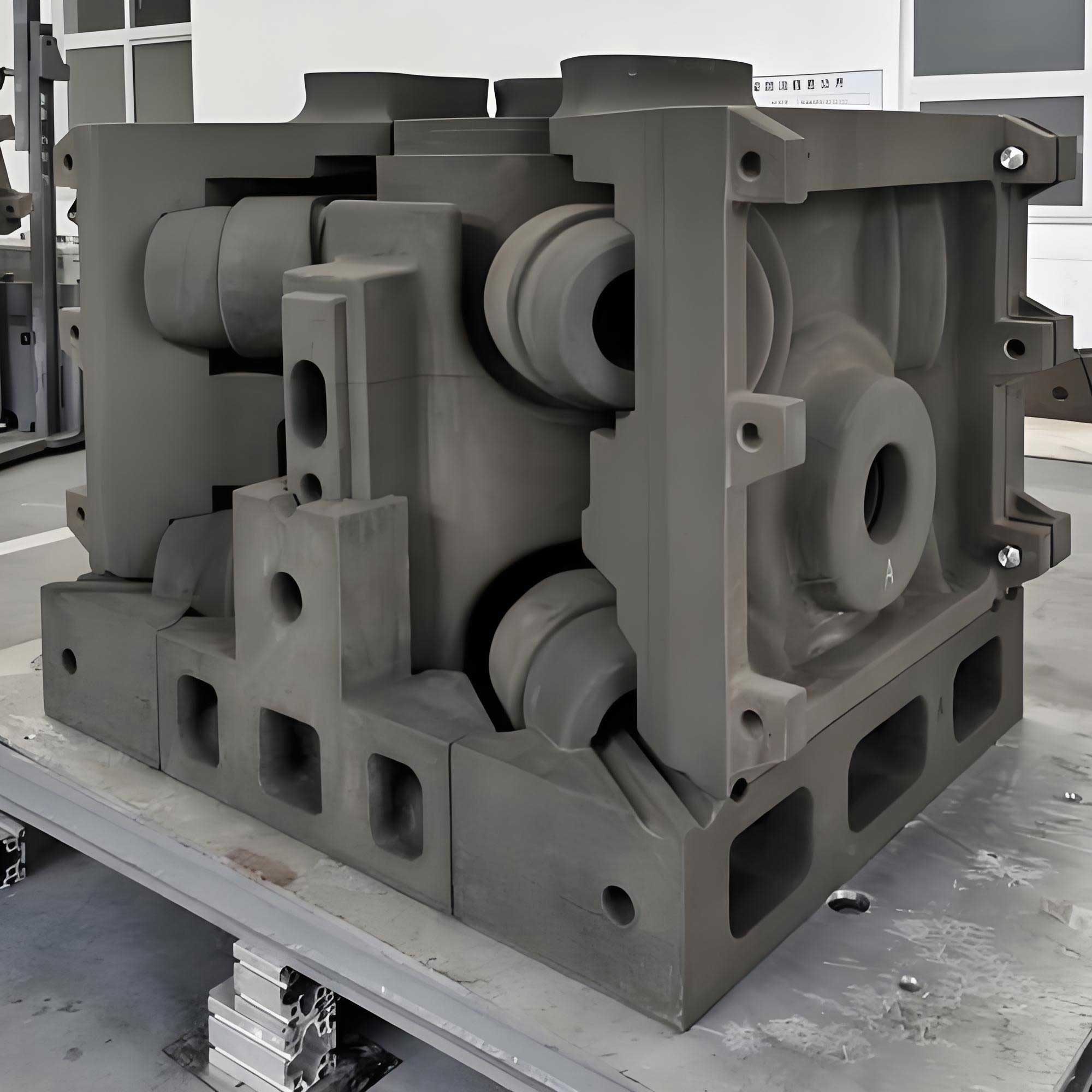
What I appreciate most about 3d printing sand casting is that it eliminates the need for pattern tooling. In conventional casting, a new shape requires a new pattern and core box. In 3D printing sand casting, only the digital data must be changed. This makes the process ideal for rapid product development, custom castings, repair applications, and production of complex hollow sand structures. The technology also supports green manufacturing because the sand can be recycled, and only the required amount of binder is used. It is a perfect match for the current demand toward intelligent and sustainable foundry production.
Fundamental Principle of 3D Printing Sand Casting
I describe the principle of this technology as the combination of powder-bed spreading and binder jetting. A thin layer of clean foundry sand is spread uniformly across the build chamber. The printhead moves over the sand bed and deposits binder droplets only where the solid sand mold should exist. The binder reacts with a curing agent already mixed into the sand, or it reacts after a post-curing step. The bonded sand becomes the mold wall, while the loose sand remains in place to support the mold during printing. Once the build is complete, the excess sand can be removed by vacuuming, brushing, or blowing.
The quality of a 3D-printed sand mold depends on several factors. The first is binder saturation. If too little binder is printed, the mold strength becomes low. If too much binder is printed, the mold may become brittle and contain excessive gas evolution during casting. The second factor is curing agent level. The amount of curing agent must be balanced with the type of sand and the required green strength. The third factor is the build orientation and slicing strategy. For printing sand casting, I normally select a layer thickness between 0.28 mm and 0.50 mm depending on the required surface finish and the feature size. The smaller the layer thickness, the finer the surface detail but the longer the printing time.
The entire digital workflow can be summarized as 3D modeling, STL conversion, slicing, image generation, printing, cleaning, and casting. I have used this workflow in many case studies and have found that standardization of the digital file stage is essential for repeatability. A typical process chain for 3D printing sand casting is illustrated below.
| Stage | Description | Key Output |
|---|---|---|
| CAD modeling | Design the pattern-less sand mold, including core, runner, riser, and gating system | Solid model with fully gated casting layout |
| STL conversion | Convert the solid model into a triangular mesh format | STL file with acceptable facet tolerance |
| Position and repair | Orient the model in virtual build space and repair mesh errors | Positioned and watertight mesh |
| Slicing | Cut the model into horizontal layers with a fixed layer thickness | Layer contours and image bitmaps |
| Parameter setup | Define print speed, binder amount, recoating speed, and overlap width | Machine-ready print job |
| Sand printing | Print binder layer by layer on the sand bed | Sand mold block with loose sand support |
| Cleaning and curing | Remove loose sand, inspect the cavity, and then perform final cure if needed | Ready-to-use sand mold |
| Pouring | Assemble cores and molds, clamp if necessary, and pour liquid metal | Final casting with controlled solidification |
I often use the following relationship to calculate the total number of slices and to estimate the printing time:
$$N = \left\lceil \frac{H}{\Delta z} \right\rceil + 1$$
where \(N\) is the number of layers, \(H\) is the total height of the sand mold in the build direction, and \(\Delta z\) is the layer thickness. The total printing time can then be expressed as:
$$T_{print} = N t_{layer} + t_{setup}$$
In this equation, \(t_{layer}\) is the time required for one complete sequence of spreading sand, jetting binder, and returning the recoater to the home position, while \(t_{setup}\) includes the time for initialization, image loading, calibration, and checking the binder supply system.
Application of 3D Printing Sand Casting to a Crankshaft Sand Mold
One practical application that I have examined is the production of a sand mold for a crankshaft. The crankshaft has a highly contoured geometry with counterweights, journals, and rod pins. To produce this casting using conventional pattern tooling, one would need a complex pattern, a core box for each internal passage, and careful assembly of the core package. With ordinary 3D printing sand casting, I can directly generate the complete sand mold with its gating system in one integrated process. This approach greatly reduces the number of mold assembly steps and improves dimensional consistency.
In this case, the 3D printing sand casting method was used to fabricate the entire crankshaft sand mold, including the inner gate, runner, sprue, pouring cup, sprue sump, and venting rods. The gating system is shown in a schematic table below. I designed the gating system so that the molten metal fills the mold smoothly and avoids turbulence. A well-designed gating system is critical in 3D printed sand casting because the permeability of the mold and the strength of the sand can be carefully controlled.
| Gating element | Function | Design consideration in 3D printed sand casting |
|---|---|---|
| Pouring cup | Receives molten metal from the ladle | Large enough to maintain a full sprue and prevent vortex formation |
| Sprue | Transfers metal vertically into the mold | Tapered shape with smooth surfaces to reduce aspiration of air |
| Sprue sump | Reduces downward velocity and pressure at bottom | Rounded bottom to avoid sand erosion |
| Runner | Distributes metal to multiple ingates | Cross-section should minimize turbulence |
| Inner gate | Controls the entry of liquid metal into the casting cavity | Positioned at low-stress zones and designed to separate cast metal from runners |
| Venting rod | Allows gas to escape from the mold cavity | Small diameter channels placed at the highest points of the cavity |
For a crankshaft, I set the gating ratio according to the standard gating principle used in foundry engineering:
$$A_{sprue} : A_{runner} : A_{gate} = 1 : 1.2 : 1.4$$
This so-called pressurizing gating system helps to keep the molten metal flowing with less aspiration. In 3D printing sand casting, the exact cross-section shapes of the sprue and runner can be made more complex than in conventional molds because there is no need to withdraw a pattern. Therefore, I can optimize the hydraulic behavior of the gating system without considering pattern draft or core assembly clearances.
Another important design task is the definition of the parting plane. For the crankshaft mold, I chose the parting surface at the center plane of the crankshaft and along the centerline of the runner. This decision simplifies the layout and allows the mold to be printed as two halves. The essential steps I used for the parting design are:
| Step | Operation | Purpose |
|---|---|---|
| 1 | Define the parting plane in the CAD environment | Separate the mold into cope and drag |
| 2 | Apply parting direction vector | Ensure each half can be cleaned and inspected |
| 3 | Create full solid bodies around the casting geometry | Generate the external shape of the sand blocks |
| 4 | Add locating features | Ensure accurate alignment of the mold halves |
| 5 | Export each half as a separate STL file | Prepare for slicing and image generation |
After the CAD models were ready, I converted them into STL format. The STL format is widely used in additive manufacturing. I used a dedicated software package to inspect the STL file for holes, flipped facets, and bad edges. For crankshaft sand molds, the orientation of the model in the build chamber has a significant effect on the final quality. For example, if the model has fine surface details or lettering on the bottom face, placing that face downward may cause support marks or rough surfaces. I normally orient such details upward. For cylindrical features such as bolt holes and journal bores, I orient them so that their axes are not exactly horizontal unless the layer thickness is low enough to avoid excessive stair-stepping.
| Feature type | Recommended placement | Reason |
|---|---|---|
| Fine surface details | Facing upward or vertical | Avoids support intrusion and improves surface finish |
| Hole and bore axes | Slightly inclined if possible | Reduces stair-step roughness in circular openings |
| Thin walls | Perpendicular to the spreading direction | Improves strength and dimensional stability |
| Thread profiles | Axis vertical and thread crest upward | Preserves thread shape and assembly surface |
Once the orientation was established, I moved all parts to positive coordinates and merged them into a single STL file. The slicing step then generated the layer images. A sand mold slicing tool takes the STL file and converts it into bitmap or PNG images with a specified layer thickness. The main parameters for slicing include image resolution, pixel width, layer height, and binder printing directions. For the crankshaft mold, I set the slice thickness to 0.3 mm. The total height of the mold block was 220 mm, so the number of layers was calculated as:
$$N = \left\lceil \frac{220}{0.3} \right\rceil + 1 \approx 735$$
The layer images were then loaded into the printing system. The printer spread sand and printed binder according to these images. During printing, I monitored the binder drop pattern by performing a nozzle test before starting the job. The binder jetting head must be clean and fully functional. If the nozzle is blocked, the sand mold will have missing binder areas and weak spots. After the printing was completed, I waited for the mold to reach a stable green strength, removed the sand block from the build chamber, and manually removed loose sand from the cavities. The crankshaft sand mold was then inspected with dimensional tools. I measured the main journal diameters, the crankpin positions, and the overall length. The measured deviations were within the tolerance of the sand casting process, confirming that ordinary 3D printing sand casting can achieve acceptable accuracy for complex crank geometry.
Hollow Sand Mold for an Intermediate Bearing Housing
In many conventional sand molds, the entire mold body is solid compacted sand. I have noticed that this dense structure can create certain disadvantages. A solid sand mold has a lower capacity to quickly remove heat from the casting because the outer surface area is limited. As a result, the cooling time of the casting is prolonged. Moreover, it is difficult to locally control the cooling rate at different positions of the casting. The lack of cooling control can lead to shrinkage porosity, hot tears, residual stress, and distortion. In response to this problem, I have used a special technique in 3d printing sand casting called hollow mold design.
A hollow sand mold is a printed mold that contains internal voids, cellular structures, ribs, trusses, or additional shells that are not directly exposed to the liquid metal. These internal features reduce the amount of sand used for the mold and change the thermal behavior of the casting process. Because a hollow mold has a larger effective surface area per unit volume, heat can be extracted from the casting faster. The position and density of the hollow structures can be varied to control the cooling locally. This is a unique advantage of 3D printing sand casting, because conventional pattern-based molding cannot easily produce such hollow internal cavities.
I used a specialized hollow-core generation software module to convert a solid sand mold model into a hollow model suitable for printing. The software takes an STL file of the sand block or core and generates a hollow version with a designed reduction in material volume. The hollow geometry can be of several types, depending on the mechanical and thermal requirements of the casting. The main design modes are described below.
Integrated Hollow Mold Design Based on Finite Difference Method
The integrated hollow design is based on a thermal simulation using the finite difference method. In this method, the mold is divided into small control volumes. The transient heat conduction equation is solved on this grid to predict the temperature evolution during solidification. The governing equation can be written as:
$$\rho c_p \frac{\partial T}{\partial t} = k \nabla^2 T + \dot{q}$$
where \(\rho\) is the density, \(c_p\) is the specific heat capacity, \(k\) is the thermal conductivity, \(T\) is the temperature, \(t\) is the time, and \(\dot{q}\) is the volumetric heat source from the solidifying metal. The finite difference discretization of the one-dimensional version of this equation is:
$$T_i^{n+1} = T_i^n + \alpha \frac{\Delta t}{\Delta x^2} \left(T_{i+1}^n – 2T_i^n + T_{i-1}^n\right)$$
where \(\alpha = k/(\rho c_p)\) is the thermal diffusivity of the sand, \(\Delta x\) is the space step, and \(\Delta t\) is the time step. By solving this equation for the entire mold, I can determine where the mold remains hot for too long and where cooling is too rapid. Then I can create hollow features at specific locations to guide the solidification front.
The integrated hollow design parameters include the basic calculation parameters, the grid step, the inner shell thickness, the outer shell thickness, the additional shell gaps, and the optional reinforcing rib parameters. The inner shell is the layer that forms the casting cavity. It must be thick enough to withstand the metallostatic pressure of the liquid metal. The outer shell provides the external strength of the mold. Between the inner and outer shells, internal cavities are generated. This design can substantially reduce the sand volume while maintaining structural integrity.
Truss-Structure Hollow Mold Design
Another form of hollow mold design that I used is the truss-structure design. In this design, the mold has an inner shell that forms the casting cavity and two additional shells outside, with gaps between them. The gaps are reinforced by truss-like struts. These struts carry the compressive load from the sand mold weight and the ferrostatic pressure. The truss pattern also creates continuous network channels for gas evacuation and for improved thermal radiation across the cavity. For the intermediate bearing housing, the estimated hollow reduction rate was 78%.
I define the hollow material reduction ratio as:
$$R_{hollow} = \left(1 – \frac{V_{hollow}}{V_{solid}}\right) \times 100\%$$
where \(V_{hollow}\) is the volume of the hollow sand mold after removing internal cavities and \(V_{solid}\) is the volume of the original solid sand mold. A hollow reduction rate of 78% means that the amount of sand consumed is only 22% of the sand that would be needed for a conventional solid mold. This has a direct impact on the printing time, sand handling cost, binder consumption, and the weight of the mold. Lightweight molds are easier to handle and can be manipulated with less powerful robotic equipment.
Composite Integrated Hollow Mold Design
I also developed a composite integrated hollow mold design for the intermediate bearing housing. This design combines the inner shell, an intermediate shell, and outer shell, with a mixture of reinforcing ribs and optimized internal voids. The composite design allows the cooling rate to be tuned in different regions of the casting. Some regions receive denser support, while other regions are made highly porous to accelerate cooling. For the intermediate bearing housing, the estimated material reduction was 74%.
The advantage of the composite design is that it provides a compromise between mechanical strength and cooling efficiency. If a hollow mold is too open, it may not survive the sand handling and mold clamping. If it is too dense, the cooling benefit is lost. In 3D printing sand casting, I can adjust the local volume fraction of the internal supports. The volume fraction is defined as:
$$\phi_{void} = \frac{V_{cavity}}{V_{total}}$$
where \(V_{cavity}\) is the volume of the internal cavities and \(V_{total}\) is the total volume enclosed by the outer boundary of the mold block. A high \(\phi_{void}\) gives faster cooling and lower sand consumption, but the mold strength must be verified with finite element structural analysis.
Segmented Hollow Mold Design
The intermediate bearing housing is a fairly complex casting. In addition to the integrated hollow design, I used a segmented approach. In this approach, the mold is split into an upper mold, a lower mold, and separate cores. Each of these segments is designed and hollowed independently. After the printed segments are cleaned, they are assembled into a complete mold system. This method is more flexible because it permits each core to have its own internal hollow structure optimized for its own geometry.
For the upper mold segment, I placed hollow cells at positions where thick sections of the casting are likely to create hot spots. For the lower mold, I designed hollow channels near the flanges to accelerate cooling and reduce distortion. For the cores, which are often the most difficult to cool, I used internal truss structures that maintain the core strength while allowing cooling air or cooling water to be applied to the core print through the hollow vents. The segmented approach also simplifies powder removal after printing, because loose sand can escape through openings in each small segment instead of being trapped inside a large hollow geometry.
| Hollow design mode | Structural features | Approximate sand reduction | Typical use |
|---|---|---|---|
| Integrated | Uniform inner and outer shells with ribs | About 70% | Simple mold blocks |
| Truss structure | Two additional shells connected by struts | Up to 78% | Bearing housings and structural castings |
| Composite | Mixed ribs, shells, and local cavities | About 74% | Castings requiring controlled directional cooling |
| Segmented | Separate cope, drag, and cores hollowed independently | Varies per segment | Complex assemblies and difficult-to-clean molds |
After designing the hollow sand mold, I performed a thermal analysis to show its advantage. The heat flow from the casting to the external environment depends on the surface area and the heat transfer coefficient. The basic convective heat transfer is described by:
$$\dot{Q} = h A \left(T_s – T_\infty\right)$$
where \(h\) is the heat transfer coefficient, \(A\) is the exposed surface area, \(T_s\) is the surface temperature of the mold, and \(T_\infty\) is the ambient temperature. In a hollow mold, the inner shell receives heat from the casting. The heat then enters the internal cavity where it is transferred by radiation and convection to the outer shell. The additional surface area at the cavity interior increases the overall effective heat removal. The cooling of a simple casting after pouring can be approximated by:
$$T(t) = T_m + \left(T_p – T_m\right) \exp\left(-\frac{h A}{\rho c_p V} t\right)$$
where \(T_m\) is the initial mold temperature, \(T_p\) is the pouring temperature, \(V\) is the volume of the casting, and \(A\) is the effective cooling surface area. From this equation, I can clearly see that an increase in \(A\) obtained by hollow structures accelerates the cooling rate and reduces the time constant of the exponential decay. This behavior allows the solidification time to be controlled so that the casting has a more uniform temperature distribution.
Slicing and Image Generation for Hollow Sand Molds
The slicing process for a hollow sand mold is similar to that for an ordinary sand mold. I first output the hollow STL model from the hollow-generation software. The file contains all the internal cavities, trusses, and shells. I then checked the normal directions of all triangular facets. The facet orientation is very important because a downward-facing normal will cause the slicing software to misinterpret the interior of the part.
In the case of the intermediate bearing hollow mold, I rotated the upper mold to a suitable position to reduce support generation and to allow loose sand to escape more easily. I then adjusted all parts so that their X, Y, and Z coordinates were non-negative. In a Cartesian coordinate system, if any part has negative coordinates, it will lie outside the buildable space of the machine. I merged all individual mold segments into one STL file for a complete build. This merging step also allowed the printer to produce the entire hollow mold in a single pass without changing jobs.
The slicing tool that I used for 3D printing sand casting can convert STL data into grayscale bitmap images. The image resolution is directly related to the nozzle pitch of the printer. The effective image width in pixels is determined by the actual printhead overlap. I used the following relationship to calibrate the image width:
$$W_{effective} = W_{nominal} – W_{overlap}$$
where \(W_{nominal}\) is the total pixel width of the entire printhead and \(W_{overlap}\) is the number of pixels covered by more than one nozzle module. A proper overlap prevents white lines between adjacent print passes. I verified the image width by printing a test pattern on paper and observing whether the overlapping bands were visible to the eye.
The slicing process includes four main steps: setting parameters, loading the model, slicing the model, and generating the final layer images. During parameter setup, I set the layer thickness, image resolution, output format, build origin, and path strategy. During the loading stage, the STL file is imported and the bounding box is checked. The slicing stage computes the intersection of each horizontal plane with the triangular facets. The final step writes the layer data into bitmap or PNG files. Each image is then loaded into the printer’s control software in order.
| Slicing step | Parameters | Notes |
|---|---|---|
| Set parameters | Layer thickness, image width, exposure or jetting pattern | Layer thickness should match the sand particle size |
| Load model | STL file, unit scale, coordinate offsets | Verify all coordinates are positive |
| Slice | Algorithm for contour filling and image rendering | Use a tolerance to avoid missing thin walls |
| Generate images | BMP or PNG output, file naming by layer number | Check the first and last layer image |
Printer Operation and Process Control
I have found that reliable operation of a sand 3D printer requires careful attention to the ink supply system. Before printing every job, I check the binder pump, the pressure of the printhead, and the condition of the nozzle. If the printhead has been idle for a long time, some nozzles may be blocked. I perform a quick test jetting pattern to verify that all nozzles are firing uniformly. If the binder droplets deviate from the intended position, the mold accuracy will be degraded.
The sand itself must also be controlled. In 3D printing sand casting, the sand is usually washed and dried. It is then mixed with a small amount of curing agent. The sand mixture is transported to the build chamber through a vacuum conveyor. I always clean the vacuum filter container before starting a new print. A blocked filter can cause inconsistent sand spreading and layer defects. I also check the sand level in the storage containers. The spreader must be able to place a smooth and uniform layer of sand over the entire build area. If the sand layer thickness varies, the binder may penetrate too deeply into one region and not enough into another.
During the printing process, I monitor the binder levels and curing agent levels periodically. The system uses peristaltic pumps to supply the curing agent. I inspect the pump tubes for wear and replace them when needed. The backpressure of the binder line must be stable to ensure a constant droplet volume. I also watch the first few layers to confirm that the sand is wetting properly and that the binder is not soaking into the sand too much or beading on the surface.
An important operational rule is that after a power failure or an emergency stop, the print job may need to be resumed. In the machine software that I use, the layer images can be reloaded. However, I must resume from the correct layer. The printer system in my experience requires that the image reload process start at an odd-numbered layer. This is related to the bidirectional printing strategy. Every two layers are printed with a regular alternating movement pattern, and the odd layer is the start of this pattern. I therefore document the last completed layer number before starting any interruption. This practice avoids a mismatch in binder path direction.
After the print job is finished, I move the printhead to the maintenance position, clean the nozzle plate carefully, and apply a moist pad or cap to keep the nozzle humidified. The binder is water-based in many cases, and if it dries inside the nozzle, it will crystallize and block the jet. Once the printhead is capped, I wait for at least one hour before removing the sand block from the machine. This waiting time allows the sand mold to gain sufficient green strength. If I remove the block too early, the sand can break, especially in thin hollow sections.
After removal, I first vacuum the loose sand from the build platform. The surrounding sand that is not bonded can be cleaned, sieved, and reused. In the case of ordinary sand molds, the used sand from the print box is recycled after screening. The hollow sand mold is then separated from the unrecycled residue. The internal cavities must be carefully emptied. I use a combination of shaking, vacuuming, and gentle brushing to remove all loose sand from the hollow channels. For complex truss structures, I may need to create additional escape holes in non-critical areas of the mold. This is a design decision that must be made during the CAD phase of 3d printing sand casting.
Quality Inspection and Data Analysis
After printing and cleaning, I inspect the sand mold using both simple instruments and digital measurement methods. For the crankshaft sand mold, I used calipers and gauges to verify critical locations. For the intermediate bearing housing hollow mold, I used a coordinate measuring machine to check the inner shell thickness and the cavity positions. The inspection data were compared with the CAD nominal values. The deviations are usually caused by binder penetration, sand expansion, layer resolution, and post-curing shrinkage.
I also evaluate the mold by measuring its weight and comparing it with the expected hollow reduction ratio. If the actual weight is much higher than expected, some internal cavities may not have been created correctly. If the actual weight is much lower, the shell may be too thin. The measured material reduction can be expressed as:
$$R_{measured} = \left(1 – \frac{m_{actual}}{m_{solid}}\right) \times 100\%$$
where \(m_{actual}\) is the actual mass of the printed mold and \(m_{solid}\) is the mass of a solid sand mold with the same external boundary. I use this formula to verify that the hollow structure was successfully reproduced during printing.
Another important quality issue is the strength of the hollow mold. Because the material has been removed from the interior, the load-carrying cross-section is reduced. I estimate the effective load-bearing area by considering the shell thickness. For a simple vertical wall, the bending stress can be approximated by:
$$\sigma = \frac{M y}{I}$$
where \(M\) is the bending moment, \(y\) is the distance from the neutral axis, and \(I\) is the second moment of area. For a hollow section, \(I\) is lower than for a solid section of the same external size. Therefore, I often add vertical ribs at the outer surface of the sand block to restore stiffness without sacrificing thermal performance. The rib spacing can be determined by structural analysis. The ribs do not interfere with the casting process because they are located outside the casting cavity.
Advantages of 3D Printing Sand Casting
I would like to summarize the practical advantages of 3d printing sand casting as follows. First, it completely removes the need for pattern tooling. When the design changes, only the digital model changes. This is especially valuable in prototype validation and in the production of customized castings. Second, it enables the production of internal geometrical features that are impossible to achieve with conventional molding. Examples include curved cooling channels, cellular truss cores, and controlled hollow structures. Third, it reduces the lead time from weeks to days. This time saving is crucial for companies competing in the modern manufacturing environment.
Fourth, 3D printing sand casting improves the casting quality by allowing thermal design of the mold. The solidification behavior can be controlled by modifying the local density and geometry of the sand mold. This helps reduce shrinkage defects, hot tearing, and residual stress. Fifth, the process is environmentally friendly. Sand is recycled, binder consumption is minimized, and the energy used for tooling production is eliminated. Finally, the complexity of a casting does not increase the cost in the same way as in conventional casting. In the table below, I compare traditional sand casting with 3D printing sand casting from the perspective of industrial application.
| Criteria | Traditional sand casting | 3D printing sand casting |
|---|---|---|
| Tooling requirement | Patterns and core boxes needed | No pattern or core box needed |
| Lead time | From several weeks to months | From one day to several days |
| Complexity capability | Limited by draft and core assembly | Nearly unlimited with digital hollow structures |
| Cooling control | Difficult to adjust locally | Can be tuned with internal cavities |
| Sand consumption | High for solid molds | Reduced by 70% to 80% with hollow design |
| Production cost for small batch | High due to tooling | Much lower |
| Sustainability | Waste from tooling and shakeout | Recyclable sand, minimal waste |
I have also observed that the cost model for 3D printing sand casting is different from conventional casting. The total cost can be written as:
$$C_{total} = C_{material} + C_{printing} + C_{labor} + C_{post} + C_{overhead}$$
The material cost \(C_{material}\) includes sand, binder, and curing agent. The printing cost \(C_{printing}\) is proportional to the machine time and energy consumption. The labor cost \(C_{labor}\) includes the operator time for file preparation, printing, and cleaning. The post-processing cost \(C_{post}\) includes curing, coating, and inspection. The overhead includes machine depreciation and maintenance. In hollow 3D printing sand casting, \(C_{material}\) is reduced significantly, and \(C_{printing}\) is also reduced because several thin layers of binder and sand can be omitted or because the smaller sand mass reduces the recoating load.
Challenges and Future Directions
Despite the advantages, I must mention some challenges that still exist in 3d printing sand casting. The first challenge is surface roughness. Layer-by-layer printing creates a stair-step effect. The mold surface may be rougher than a machine-machined pattern. For many castings, a rough surface can be tolerated because the casting is later machined. For other castings, however, the surface finish must be improved by applying a coating or manually smoothing the mold.
The second challenge is the strength of large molds. In 3D printing sand casting, the mold is made of bonded sand and is often hollow. Large molds may crack under their own weight during lifting. To avoid this, I integrate additional ribs and trusses into the hollow design. The design must be checked with finite element analysis to ensure that the stress levels are below the permissible strength of the printed sand.
The third challenge is the limitation of the binder chemistry. Binders used in sand 3D printing must provide high strength, low gas evolution, good shaking-out behavior, and compatibility with various alloys. I have used furan-based binders, phenolic binders, and inorganic binders. The selection depends on the casting temperature and the required surface finish. The binder saturation level must be optimized for every sand type.
The future of 3d printing sand casting will likely involve more intelligent process control. I believe that machine learning algorithms can help predict the optimal printing parameters based on the geometry of the mold and the thermal requirements of the casting. Inline sensors can monitor the binder drop size, sand moisture, temperature, and curing rate. If these signals are fed into a closed-loop controller, the print quality can be improved even further. In addition, the integration of computational casting simulation with 3D printing data will allow the prediction of hot spots and automatic design of hollow cooling channels in real time.
Another promising direction is the combination of 3D printing sand casting with casting process simulation. The cooling curve in the hollow mold can be predicted by solving the heat conduction equation with the actual hollow geometry. I use the finite difference method to simulate the temperature field. The simulated cooling rates can be compared with the experimental cooling rates measured by thermocouples embedded in the sand mold. This validation improves the reliability of the simulation model and helps to design better molds in the next iteration.
The workflow for simulation-driven hollow sand mold design can be summarized by the following iterative loop:
| Step | Action | Input / output |
|---|---|---|
| 1 | Create casting geometry | CAD model of the casting |
| 2 | Design initial solid sand mold | Sand block and core geometry |
| 3 | Run thermal simulation | Temperature history and hot spot map |
| 4 | Identify critical regions | Regions with slow cooling or rapid cooling |
| 5 | Generate hollow structure | Hollow STL file with optimized cavities |
| 6 | Run structural simulation | Stress and displacement of the mold |
| 7 | Print and experimentally verify | Thermocouple data and casting quality |
By repeating this loop, I can find a hollow sand mold design that provides directional solidification, low residual stress, and minimal distortion. The same loop can also be used to optimize the runner and riser system. The riser size can be reduced because the hollow mold improves feeding efficiency. The gating system can be made smaller and lighter, further increasing the yield of the casting process. In conventional foundry practice, a large riser means a large amount of metal is discarded after casting. With 3D printing sand casting, the hollow structure can be placed around the riser neck to keep it hot longer with a smaller riser volume.
I have also experimented with functionally graded sand molds. In a functionally graded mold, the sand density or binder content is altered across the thickness of the mold. For example, the inner layer near the casting can be made with a higher binder content to provide a smooth surface, while the outer layer can be porous to allow gas escape. The printhead can deposit different binder concentrations at different positions. This capability is unique to 3d printing sand casting and impossible to achieve with conventional molding methods. The thermal conductivity and permeability of the mold can therefore be spatially controlled in a way that was previously impossible.
One practical formula for the effective thermal conductivity of a composite sand mold is:
$$k_{eff} = \phi_{sand} k_{sand} + \phi_{air} k_{air}$$
where \(\phi_{sand}\) and \(\phi_{air}\) are the volume fractions of the sand matrix and the air voids, respectively. In a hollow mold, \(\phi_{air}\) increases in the hollow zones, so \(k_{eff}\) decreases if air has lower conductivity than sand. However, the larger internal surface area enables more radiative heat transfer at high temperatures. Therefore, the overall cooling performance may increase, especially if the internal cavities are large enough. The thermal behavior depends strongly on the geometry and the temperature. For this reason, I prefer to perform a full thermal simulation for every new hollow mold design rather than relying on simple estimates.
Practical Process Notes for Operators
When I train new operators in 3d printing sand casting, I emphasize the importance of a complete pre-print checklist. The checklist includes checking the printhead communication, cleaning the nozzle plate, pressing the peristaltic pump rollers to remove air bubbles, inspecting the binder filters, and confirming that the curing agent container has enough material. I also check the sand level in both the fresh sand storage and the overflow collector. The vacuum sand conveyor must be free of blockages, and the filter must be clean. The pressure of the compressed air for the sand spreader and the vacuum system must be within the operating range.
| Phase | Check item | Typical issue if ignored |
|---|---|---|
| Before printing | Printhead nozzle test | Weak or missing binder lines in the mold |
| Before printing | Binder path priming | Air bubbles cause droplet failure at the beginning |
| Before printing | Sand moisture and curing agent content | Poor green strength and slow hardening |
| Before printing | Build platform leveling | Layer thickness variation and collision |
| During printing | Binder and resin levels | Job stops halfway or incomplete mold |
| During printing | Recoater blade condition | Grooves or streaks in the sand layer |
| During printing | Sliced image range | Printing the wrong layers after interruption |
| After printing | Printhead capping | Nozzle drying and blockage |
| After printing | Wait time before removal | Fragile mold or broken shells |
During printing, the operator should visually inspect the sand surface after each spreading pass, especially in the initial layers. If there is a problem with the recoater blade, it leaves a groove that can be seen as a light streak on the sand surface. The operator must stop the job, clean the blade, and resume. However, because resuming from a random layer can be difficult in some systems, I prefer to run a short test print before starting a critical mold. This test print should include the same layer thickness and the same binder saturation as the real job.
After the mold is removed from the build chamber, I use a soft brush to clean the surface. In hollow molds, the loose sand from the internal cavities is often removed with a vacuum tube. I have designed small escape holes in the outer shell so that the loose sand can flow out easily. These holes are placed in areas that do not affect the geometry of the casting. The escape holes are filled later with a sand paste or left open to act as vent holes during pouring. The size and location of escape holes must be considered during the design phase.
The used sand from the cleaning station should be collected and separated from the larger bonded pieces. The bonded sand cannot be reused because its binder has already set and its particle surface is contaminated. However, the loose sand that has never been in contact with binder can be recycled. I recommend sieving the recycled sand to remove all particles smaller than the average grain size, because fine dust lowers the permeability of the final mold. A high permeability is necessary to allow gas to escape through the mold walls during casting.
Economic and Environmental Impact
From an economic point of view, 3d printing sand casting is especially suitable for batch sizes of one to a few hundred pieces. In this range, the elimination of tooling costs outweighs the higher machine running cost. I have calculated that for a typical complex casting, the break-even quantity is between one and ten castings compared to conventional machining of patterns. For small batch production, the cost saving can be as high as 70% in terms of tooling investment. This is a strong argument for adopting the technology in job shops and foundries.
The environmental impact is also positive. A conventional pattern shop uses wood, metal, plastic, CNC machines, and cutting fluids. In contrast, 3D printing sand casting uses sand and a small amount of binder. The sand can be reused many times. The mold itself is lighter, which reduces the energy consumed during handling and heating. The removal of the core box and pattern also eliminates the waste that is produced when a pattern becomes obsolete. I believe that 3D printing sand casting is a clean technology that supports the global trend toward green manufacturing.
Let me define a simple coefficient for the environmental benefit of hollow sand molds:
$$E_{saving} = \frac{m_{solid} – m_{hollow}}{m_{solid}} \times 100\%$$
For the intermediate bearing housing, this coefficient was 78% in the truss design and 74% in the composite design. This means that only about one quarter of the original sand volume was used. The reduction in sand means less material to transport, less binder to consume, and less dust to handle. It also means that the build chamber can be filled with more molds if they are arranged vertically or side by side. The printer productivity is therefore improved when hollow molds are used.
Conclusion
In conclusion, I have presented practical applications of 3d printing sand casting in the production of ordinary sand molds and hollow sand molds. The ordinary sand mold example of a crankshaft demonstrates that 3D printing sand casting can produce a complex gated sand mold without any pattern. The hollow sand mold example of an intermediate bearing housing demonstrates how the additive manufacturing capability can create internal trusses and shells that reduce material use and improve cooling control. I have found that hollow sand structures are particularly valuable for controlling the solidification of thick castings and avoiding casting defects.
The practical knowledge gained from these cases shows that 3D printing sand casting is not merely a prototyping method. It is a production-grade manufacturing process. The digital nature of the process allows fast design changes and local optimization of the mold. The ability to print hollow structures provides thermal and structural advantages that are impossible to achieve with conventional casting. Furthermore, the technology reduces costs, saves energy, and minimizes material waste. I believe that the future of foundry manufacturing will increasingly rely on 3d printing sand casting as a core technology rather than as an alternative method.
In my view, the combination of simulation, digital design, and binder jetting sand printing will lead to new casting solutions that are lighter, stronger, and more reliable. As machine speed and binder materials continue to improve, the cost of sand 3D printing will fall further. In the near future, I expect to see large castings with complex internal cooling channels printed as monolithic sand molds, eliminating assembly errors and enabling true near-net-shape casting. The practical applications described here are just the beginning of the technological transformation in sand casting.