
I present a comprehensive study on the design and application of waste heat recovery from the surface of sand molds used in 3D printing sand casting, specifically during the cooling stage. My research introduces a thermoelectric generation-based method to recover residual heat, establishes a predictive model for total energy recovery, and proposes an optimized sand mold structure to enhance the recovery efficiency. Throughout this thesis, the central concept of “3d printing sand casting” is systematically integrated with waste heat recovery technology, aiming to improve energy utilization and promote sustainability in the foundry industry. The work is validated through experiments conducted on two cast components, demonstrating the feasibility and effectiveness of the proposed approach. My results indicate that the optimized structure can increase the recovered electrical energy by 45%–70% compared to conventional dense sand molds, while the prediction model achieves an average accuracy of 92.2%.
1 Introduction
Sustainable manufacturing has become a critical goal in modern industry, aiming to reduce resource consumption and energy usage while maintaining production efficiency. The manufacturing sector accounts for a significant share of global energy consumption, and China, as a major manufacturing country, consumed approximately 2.8 billion tons of standard coal equivalent in 2022, representing about 56% of its total energy consumption. Among various manufacturing processes, casting is a fundamental technology for producing metal components, and sand casting remains the most widely used method due to its low cost, flexibility, and suitability for complex geometries. However, conventional sand casting processes suffer from low energy efficiency, with the average energy utilization rate in China being less than 50%. The casting industry alone consumes about one-third of the total energy used in the machinery industry. These facts highlight an urgent need for improving energy efficiency and reducing emissions in sand casting operations.
To address these challenges, advanced technologies have been introduced into the casting sector, among which “3d printing sand casting” has emerged as a promising alternative. This technology allows for the rapid production of sand molds with high geometric flexibility, reduced lead times, and lower material consumption. Moreover, it enables the design of complex internal structures that are impossible to achieve with traditional molding methods. Many researchers have studied the effects of process parameters, binder materials, and mold structures on the quality and efficiency of 3d printing sand casting. For instance, some found that the thickness of the 3D printed mold influences solidification time and microstructure, while others optimized coating speed and print resolution to balance strength and permeability. Structural innovations such as truss lattices, rib reinforcements, porous layouts, and hollow cavities have been proposed to reduce sand usage and control cooling rates. These studies primarily focused on improving casting quality, shortening production cycles, or lowering direct energy consumption. However, the residual heat released during the cooling stage, which carries a substantial amount of thermal energy, has not been effectively recovered in the context of 3d printing sand casting.
Waste heat recovery (WHR) has been widely explored in industrial processes, including organic Rankine cycles, heat exchangers, and thermoelectric generators (TEGs). Thermoelectric generation is particularly attractive for small-scale, distributed heat sources because it has no moving parts, is scalable, and can be attached directly to surfaces. In the steel and aluminum industries, TEGs have been installed on hot slabs and furnace walls to convert radiative heat into electricity. Nevertheless, few studies have focused on applying TEGs to recover waste heat from sand molds during the cooling phase of 3d printing sand casting. This gap motivated my research, in which I integrate thermoelectric generation with 3d printing sand casting to create a novel waste heat recovery methodology.
The primary objectives of my work are: (1) to design a waste heat recovery device based on thermoelectric generation that can be applied to the surface of a 3D printed sand mold; (2) to develop a prediction model for the total recoverable electrical energy using the thermal circuit method; and (3) to propose a structural optimization strategy for the sand mold itself, aiming to enhance the amount of heat that reaches the recovery device. Through numerical simulations and physical experiments, I demonstrate that the proposed methodology not only recovers a significant amount of energy but also accelerates the cooling process without compromising casting quality. This work contributes to the sustainable development of the foundry industry by providing a practical pathway to utilize the abundant waste heat in 3d printing sand casting.
2 Waste Heat Recovery Methodology
2.1 Principle of Thermoelectric Generation
Thermoelectric generation is based on the Seebeck effect, which states that a temperature difference between two dissimilar conductors or semiconductors produces an electromotive force. The voltage generated is proportional to the temperature difference, expressed as:
$$ U_s = \alpha_s (T_{s1} – T_{s2}) $$
where \(U_s\) is the Seebeck voltage, \(\alpha_s\) is the Seebeck coefficient, and \(T_{s1}\), \(T_{s2}\) are the temperatures at the hot and cold junctions, respectively. Commercial thermoelectric modules consist of multiple p-type and n-type semiconductor elements connected electrically in series and thermally in parallel, sandwiched between ceramic substrates. The overall open-circuit voltage of a module is the sum of the contributions of all junctions. The energy conversion efficiency of typical TEGs used for low-grade heat recovery is only about 2%, but they are still valuable in applications where simplicity, reliability, and unattended operation are more important than high efficiency.
In the context of 3d printing sand casting, the sand mold is a natural heat source during the cooling stage. After molten metal is poured into the cavity, the heat is gradually transferred to the sand mold, raising its surface temperature. Depending on the casting size and wall thickness, the surface temperature can reach hundreds of degrees Celsius. A thermoelectric generator attached to the mold surface can exploit the temperature difference between the hot mold surface and the ambient air (via a cold-side heat sink) to produce electricity. The main technical challenge lies in ensuring good thermal contact and maintaining the TEG temperature within its safe operating range.
2.2 Feasibility of the Proposed Approach
The feasibility of using TEGs on the surface of a 3D printed sand mold stems from several advantages of the 3D printing process. First, 3D printed sand molds have a smoother surface finish than conventional sand molds confined in flasks, reducing the contact thermal resistance between the mold and the TEG hot side. Second, the high design freedom of 3d printing sand casting allows the integration of mounting features, recesses, or flat platforms on the mold surface, which are impossible to achieve with traditional compaction molding. Third, the mold is usually allowed to cool in an open, well-ventilated area after pouring, which facilitates natural convection on the cold side of the module. The absence of mechanical constraints, such as steel flasks, also permits direct placement of the recovery device. Therefore, I selected 3D printed sand molds as the target application platform for thermoelectric-based waste heat recovery.
2.3 Design of the Waste Heat Recovery Device
The proposed waste heat recovery device is composed of three main parts: a heat-spreading plate (hot side), thermoelectric modules, and a finned heat sink (cold side). A schematic representation of the device and its heat transfer path is given below.
To ensure uniform temperature distribution on the hot side, I used a 1 mm thick copper plate as a heat spreader. The copper plate is attached to the surface of the sand mold and the TEG modules are mounted on top of it. The cold side consists of an aluminum finned heat sink, which dissipates heat to the ambient air through natural convection. The modules are connected electrically in a combination of series and parallel groups to provide a useful voltage and current while maintaining reliability. Thermal interface materials (TIMs) are applied between the mold and the copper plate, between the copper plate and the TEGs, and between the TEGs and the heat sink to reduce contact resistance. The entire device is lightweight and easy to install/remove, which is essential in a foundry environment where the device must be detached before shakeout. Table 1 lists the main components and materials used in the device.
| Component | Material | Dimensions / Specification |
|---|---|---|
| Heat spreader | Copper | Thickness: 1 mm, conductivity: 377 W/m·K |
| TEG module | BiTe-based | 40 mm × 40 mm, Seebeck coefficient: 0.01506 V/K |
| Thermal interface material | Silicone-based | Thickness: 0.5 mm, conductivity: 15 W/m·K |
| Heat sink | Aluminum | Base 5 mm, fin height 25 mm, fin thickness 3 mm |
| Connecting wires | Copper | AWG 14 |
2.4 Placement Strategy
Due to the cost of thermoelectric modules, it is impractical to cover the entire surface of a sand mold. I therefore developed a placement methodology to determine the optimal location for the recovery devices. The procedure is as follows:
- Analyze the temperature distribution of the sand mold using casting simulation software (e.g., ProCAST) before physical production.
- Identify the high-temperature regions on the mold surface that meet the temperature threshold for meaningful heat recovery.
- Select the region with the highest average temperature and sufficient area to accommodate the TEG modules.
- If the peak temperature exceeds the maximum operating temperature of the TEG, delay the installation of the recovery device until the surface cools down to a safe level.
By following these steps, I ensured that the recovery devices were placed on the most promising areas, maximizing the total recovered energy while safeguarding the device from overheating.
3 Prediction Model for Total Recovered Energy
3.1 Heat Transfer Path and Thermal Resistance Network
The heat transfer path from the sand mold surface to the ambient air can be idealized as a series of thermal resistances, as illustrated in the following equivalent circuit model. The heat flow \(\Phi\) through the recovery device is driven by the temperature difference between the mold surface \(T_s\) and the ambient air \(T_{air}\).
The components of the thermal resistance network are:
- \(R_{plate}\): conduction resistance of the copper spreader,
- \(R_{si}\): thermal resistance of the TIM layers (two layers, each on the hot and cold sides of the TEG),
- \(R_{TEG}\): conduction resistance of the thermoelectric module,
- \(R_{sink}\): conduction resistance of the heat sink base,
- \(R_{convection}\): convective resistance from the heat sink to the ambient air.
The total resistance is expressed as:
$$ R_{total} = R_{plate} + 2R_{si} + R_{TEG} + R_{sink} + R_{convection} $$
The heat flow can be calculated using Fourier’s law:
$$ \Phi = \frac{T_s – T_{air}}{R_{total}} $$
Then, the temperature difference across the TEG modules is:
$$ \Delta T_{TEG} = \Phi \cdot R_{TEG} = \frac{R_{TEG} (T_s – T_{air})}{R_{total}} $$
3.2 Calculation of Individual Thermal Resistances
3.2.1 Spreader plate resistance
The thermal resistance of the copper plate is given by:
$$ R_{plate} = \frac{\delta_{plate}}{A \lambda_{plate}} $$
where \(\delta_{plate}\) is the plate thickness, \(A\) is the area of a single TEG, and \(\lambda_{plate}\) is the thermal conductivity of copper.
3.2.2 TIM resistance
Similarly, the TIM resistance is:
$$ R_{si} = \frac{\delta_{si}}{A \lambda_{si}} $$
where \(\delta_{si}\) is the thickness of the TIM layer and \(\lambda_{si}\) is its thermal conductivity.
3.2.3 Thermoelectric module resistance
The module resistance is calculated by considering the ceramic substrates, copper conducting strips, and the semiconductor elements. The total resistance is:
$$ R_{TEG} = 2R_{ceramic} + \frac{1}{N_{PN}} \left(2R_{cu} + \frac{R_P R_N}{R_P + R_N}\right) $$
where \(N_{PN}\) is the number of semiconductor pairs, \(R_{ceramic}\) is the resistance of each ceramic substrate, \(R_{cu}\) is the resistance of each copper strip, and \(R_P\), \(R_N\) are the resistances of the p-type and n-type elements. Each of these can be calculated as \(R = \delta / (\lambda A)\), using corresponding dimensions and thermal conductivities.
3.2.4 Heat sink resistance
The heat sink resistance combines the resistance of the base plate and the convective resistance of the fins. The base resistance is:
$$ R_{base} = \frac{\delta_{base}}{A \lambda_{base}} $$
The convective resistance from the fin array is expressed using fin efficiency \(\eta_f\):
$$ R_{fin} = \frac{1}{\eta_f h n A_f + h A_b} $$
where \(h\) is the natural convection heat transfer coefficient, \(n\) is the number of fins, \(A_f\) is the surface area of each fin, \(A_b\) is the exposed base area, and \(\eta_f\) is the fin efficiency for rectangular straight fins, given by:
$$ \eta_f = \frac{\tanh(m L’)}{m L’} $$
with \(m = \sqrt{hP/(\lambda_{fin} A_{fin})}\) and \(L’ = L + b/2\). The total heat sink resistance is the sum:
$$ R_{sink} + R_{convection} = R_{base} + R_{fin} $$
3.3 Sand Mold Surface Temperature Model
The surface temperature of the sand mold in a given recovery region varies with time. To predict the recovered energy, I need to know the average temperature \(T_s(t)\) as a function of time. This can be obtained from finite element simulation results. By selecting the recovery region and averaging the nodal temperatures, a time-temperature curve is obtained. I then fit this curve to a rational function form. For example, in one of the validation cases, the fitted expression was:
$$ f_s(t) = \frac{7.901t^3 + 48520t^2 + 70020000t – 10300000}{t^3 + 827.8t^2 + 4185000t + 657800} $$
where \(t\) is the time in seconds. This function remains valid until the end of the cooling period.
3.4 Total Recovered Energy Prediction
According to the Seebeck effect, the voltage generated by a single TEG module is:
$$ U = \alpha \Delta T_{TEG} $$
The electric power delivered to a load resistance \(R_{load}\) is:
$$ P_{single} = \frac{U^2}{R_{load}} = \frac{\alpha^2 \Delta T_{TEG}^2}{R_{load}} $$
For a recovery device containing \(n_s\) modules in series and \(n_p\) groups in parallel, the total output power is:
$$ P_{total} = \frac{n_p n_s^2 \alpha^2 \Delta T_{TEG}^2}{R_{load}} $$
Integrating the power over the recovery time interval \(t_0\) to \(t_1\) gives the total recovered electrical energy:
$$ E_{recovered} = \int_{t_0}^{t_1} P_{total} \, dt = \frac{n_p n_s^2 \alpha^2 R_{TEG}^2}{R_{load} R_{total}^2} \int_{t_0}^{t_1} [f_s(t) – T_{air}]^2 \, dt $$
This is the final prediction model. It allows me to estimate the energy output based on the known geometry of the device, the thermal properties of materials, and the simulated temperature history of the sand mold.
3.5 Model Validation
To validate the prediction model, I conducted a small-scale experiment using a single TEG module (size 40 mm × 40 mm) attached to a 3D printed sand mold of an impeller casting. The mold dimensions were 276 mm × 236 mm × 197 mm. The simulation predicted that one side of the mold had a maximum temperature of 114.9 °C, which is below the 250 °C limit of the TEG. The ambient temperature was 20 °C. The load resistance was 100 Ω. Data were collected over 21,475 seconds. The predicted total recovered energy was 52.65 J, while the experimental value was 57.65 J, giving a mean voltage error of 12.59% and an accuracy of 91.33%. The difference is attributed to the fact that actual sand molds have a lower effective thermal conductivity than the homogeneous solid modeled in simulation, due to porosity and the presence of air gaps. This initial validation confirmed that the model is sufficiently accurate for practical purposes.
4 Optimization of Sand Mold Structure for Enhanced Heat Recovery
4.1 Geometric Parameters Influencing Heat Recovery
The total recovered energy from a waste heat recovery device depends on the surface temperature of the sand mold. For a given casting geometry, the cavity design is fixed by the product requirements, so the only adjustable parameters are the mold geometry, namely the overall dimensions, wall thickness, and internal structure. In conventional dense sand molds, the wall thickness is usually large (20–200 mm) to provide sufficient strength, which acts as a thermal barrier and reduces the surface temperature. Reducing the wall thickness would increase the surface temperature and thus improve heat recovery, but it would also weaken the mold. 3D printing technology overcomes this limitation by allowing the inclusion of reinforcement structures while keeping the shell thin. Therefore, the optimization problem reduces to finding the optimal internal support structure that maintains mechanical strength while maximizing heat transfer to the surface.
4.2 Comparative Analysis of Different Sand Mold Structures
To evaluate the effect of different internal structures on the heat recovery output, I designed a test casting shaped like the digit “8”. The casting volume was 50,000 mm³, with maximum dimensions of 40 mm × 40 mm × 80 mm and a wall thickness of 5 mm. The material was A356 aluminum alloy. I designed four types of 3D printable sand molds: (1) conventional dense structure, (2) truss lattice structure, (3) rib-reinforced structure, and (4) porous structure, in addition to a (5) hollow structure. All molds were simulated using ProCAST under identical casting conditions (pouring temperature 750 °C, interface heat transfer coefficient 500 W/m²·K, natural air cooling). The recovery device used for this comparison consisted of two TEG modules in series, sized 40 mm × 80 mm. The maximum operating temperature of the TEG was 250 °C. For structures where the surface temperature exceeded this limit, the device installation was delayed accordingly. The predicted recovered energy for each structure is summarized in Table 2.
| Structure | Wall thickness (mm) | Sand volume (mm³) | Cooling time (s) | Max surface temp (°C) | Recovery time (s) | Recovered energy (J) |
|---|---|---|---|---|---|---|
| Dense | 20 | 1,218,266 | 3,361 | 171.17 | 3,361 | 66.32 |
| Truss | 8 | 802,855 | 2,858 | 352.99 | 2,398 | 100.56 |
| Rib (original) | 8 | 719,544 | 2,586 | 215.67 | 2,586 | 40.34 |
| Rib (optimized) | 13 | — | 2,603 | 196.55 | 2,603 | 73.98 |
| Porous | — | 967,840 | 1,491 | 79.23 | 1,491 | 1.88 |
| Hollow | 20 | 1,079,267 | 3,452 | 189.68 | 3,452 | 74.14 |
From this analysis, the truss lattice structure was found to be the most effective for heat recovery, yielding 100.56 J, which is 51.63% higher than the dense mold. The truss structure has a thin shell (8 mm) and widely spaced vertical/horizontal struts that do not interfere with the placement of the recovery device. In contrast, the original rib structure had a rough surface with many gaps, reducing the effective contact area with the TEG hot side and lowering the recovered energy to 40.34 J. However, after filling the gaps to create a flat recovery surface (optimized rib), the recovered energy increased to 73.98 J. The porous structure, despite its many cavities, caused rapid cooling because of increased surface area with air, resulting in a very low recovered energy of 1.88 J. The hollow structure, which includes a sealed air gap, improved insulation and raised the surface temperature, yielding 74.14 J, but still less than the truss structure.
Based on these results, I selected the truss lattice structure as the basis for the optimized sand mold design. The design methodology is described in the next subsection.
4.3 Design Optimization Methodology
To maximize the recovered energy, the sand mold should have a thin shell in the recovery area, a flat and continuous outer surface to ensure good thermal contact, and a supporting structure that does not interfere with the recovery device. The design process is as follows:
- Determine the thickness of the shell based on the hydrostatic pressure of the molten metal and the allowable stress of the sand material. Use the formula:
$$ d_{min} > \frac{F_1}{\sigma(T) \, l_{min}} $$
where \(F_1\) is the total static pressure force, \(\sigma(T)\) is the high-temperature tensile strength of the sand, and \(l_{min}\) is the minimum perimeter of the casting cross-section.
- Design the truss supports by calculating the required cross-sectional area to withstand the additional dynamic pressure (about 1.3–1.5 times the static pressure). The side length of a square strut is:
$$ r > \sqrt{\frac{S_3}{n}} $$
where \(S_3\) is the total cross-sectional area required for the support and \(n\) is the number of struts.
- Modify the shell geometry in the predefined recovery region to create a flat platform that matches the footprint of the recovery device. This step is essential to eliminate air gaps and maximize the contact area.
- Position the truss struts so that they do not intersect the recovery platform but are still placed close enough to serve as mounting supports for the recovery device. If necessary, add small extension platforms on the struts to hold the recovery device.
- Verify the mechanical integrity of the final mold through structural simulation.
This flowchart summarizes the iterative design procedure. Following this method, I redesigned the sand molds for two industrial castings: an end cover and an engine block. The details of these case studies are given in the next section.
5 Case Studies: Application to Industrial Castings
5.1 End Cover Casting
The first case is a relatively simple end cover casting (volume 377,407 mm³, maximum dimensions 180 mm × 180 mm × 30 mm). It was cast as a two-cavity mold. The conventional dense sand mold had outer dimensions of 460 mm × 303 mm × 180 mm, with a sand volume of 24,022,773 mm³ and a weight of 33.6 kg. Using ProCAST, I simulated the casting process. The cooling time (until the casting reached 100 °C) was 7,475 seconds. The temperature field on the mold surface showed several concentrated hot spots on the sides. I selected five recovery regions and arranged a total of 14 TEG modules (seven in series, two parallel groups). The total coverage area was 0.0224 m². The maximum surface temperature in these regions was 130.71 °C, below the TEG limit, so the recovery devices could operate during the entire cooling period.
Using my prediction model, I fitted the average temperature of the recovery regions to a rational function and calculated the expected recovered energy as 1,621 J. I then physically 3D printed the mold, performed a real pouring, and measured the actual recovered energy to be 1,728 J. The prediction accuracy was 93.8%. This confirmed the reliability of the model for a realistic casting.
5.2 Engine Block Casting
The second case was a more complex engine block casting (volume 4,340,380 mm³, maximum dimensions 392 mm × 257 mm × 202 mm). The conventional dense sand mold had outer dimensions of 530 mm × 442 mm × 342 mm, a sand volume of 74,988,395 mm³, and a weight of 104.9 kg. The simulation gave a cooling time of 20,994 seconds. The surface temperature analysis revealed three major high-temperature regions on the front and side faces. I arranged 24 TEG modules (six in series, four parallel groups), covering 0.0384 m² of the surface. The highest surface temperature was 124.5 °C, again below the TEG limit. The predicted recovered energy was 6,071 J, while the experimental value was 6,703 J, resulting in an accuracy of 90.5%.
5.3 Optimized Truss Structure Design
For both castings, I applied my optimization methodology to design truss-structure sand molds. For the end cover, the shell thickness was calculated to be 10 mm, and the longitudinal struts were 10 square columns of 20 mm × 20 mm. The overall mold dimensions were reduced to 450 mm × 281 mm × 175 mm, with a sand volume of 7,678,348 mm³ and a weight of 10.75 kg, representing a 68% reduction in volume compared to the dense mold. The cooling time dropped to 4,583 seconds (38.7% shorter). The recovery regions were relocated to the now-flat surfaces, and the recovery devices were positioned on the truss supports. Because the maximum surface temperature reached 460.77 °C (average 273.88 °C), the device installation was delayed until the temperature fell below 200 °C, which occurred after 1,763 seconds. The recovery time was thus 2,820 seconds. The prediction model gave a recovered energy of 2,774 J, while the experimental result was 2,936 J, corresponding to an accuracy of 94.5%.
For the engine block, the optimized truss mold had a shell thickness of 15 mm and nine 30 mm × 30 mm vertical struts. The mold volume was 36,102,612 mm³, a 51.9% reduction, and the weight was 50.54 kg. The cooling time was 9,904 seconds (52.8% shorter). Four recovery regions, each 120 mm × 80 mm, accommodated the 24 TEG modules. The peak surface temperature was 353.84 °C, so installation was delayed until 4,274 seconds, leaving a recovery window of 5,630 seconds. The predicted recovered energy was 8,789 J, while the actual measured energy was 9,752 J, yielding an accuracy of 90.1%. These experimental results confirm that the truss structure not only enhances heat recovery but also accelerates the overall casting cooling, thereby improving productivity.
6 Results and Discussion
6.1 Summary of Recovered Energy and Model Accuracy
The experimental results from the two case studies are summarized in Table 3. The total actual recovered energy from all experiments was 21,119 J. The prediction model achieved an average accuracy of 92.2% across the four cases, which is sufficient for engineering design purposes. The predicted values were consistently slightly lower than the measured ones. This can be attributed to the fact that the actual thermal conductivity of the 3D printed sand is lower than the theoretical value used in the simulation, due to porosity and the presence of micro-air gaps. This causes the mold to retain heat longer and sustain a higher surface temperature than predicted, leading to a higher recovered energy.
| Casting | Mold type | Recovery time (s) | Actual energy (J) | Predicted energy (J) | Accuracy (%) |
|---|---|---|---|---|---|
| End cover | Dense | 7,475 | 1,728 | 1,621 | 93.8 |
| End cover | Optimized truss | 2,820 | 2,936 | 2,774 | 94.5 |
| Engine block | Dense | 20,994 | 6,703 | 6,071 | 90.5 |
| Engine block | Optimized truss | 5,630 | 9,752 | 8,789 | 90.1 |
6.2 Effect of Sand Mold Structure on Heat Recovery
As evidenced by the experiments, the optimized truss structure significantly improves the waste heat recovery performance. In both castings, the recovered energy increased by approximately 70% for the end cover (from 1,728 J to 2,936 J) and by 45% for the engine block (from 6,703 J to 9,752 J). The average recovery power was boosted from 0.23 W to 1.04 W for the end cover, and from 0.32 W to 1.73 W for the engine block, representing a 3-to-4 times improvement. Moreover, the recovery time was shortened by 62% and 57% for the two cases, respectively, because the thin shell and exposed struts promote faster heat transfer from the casting to the mold surface, enabling the TEG to operate at a higher temperature difference for a shorter duration. This also aligns with the sustainable manufacturing goal of improving energy efficiency and production throughput.
6.3 Discussion on the Position of the Image
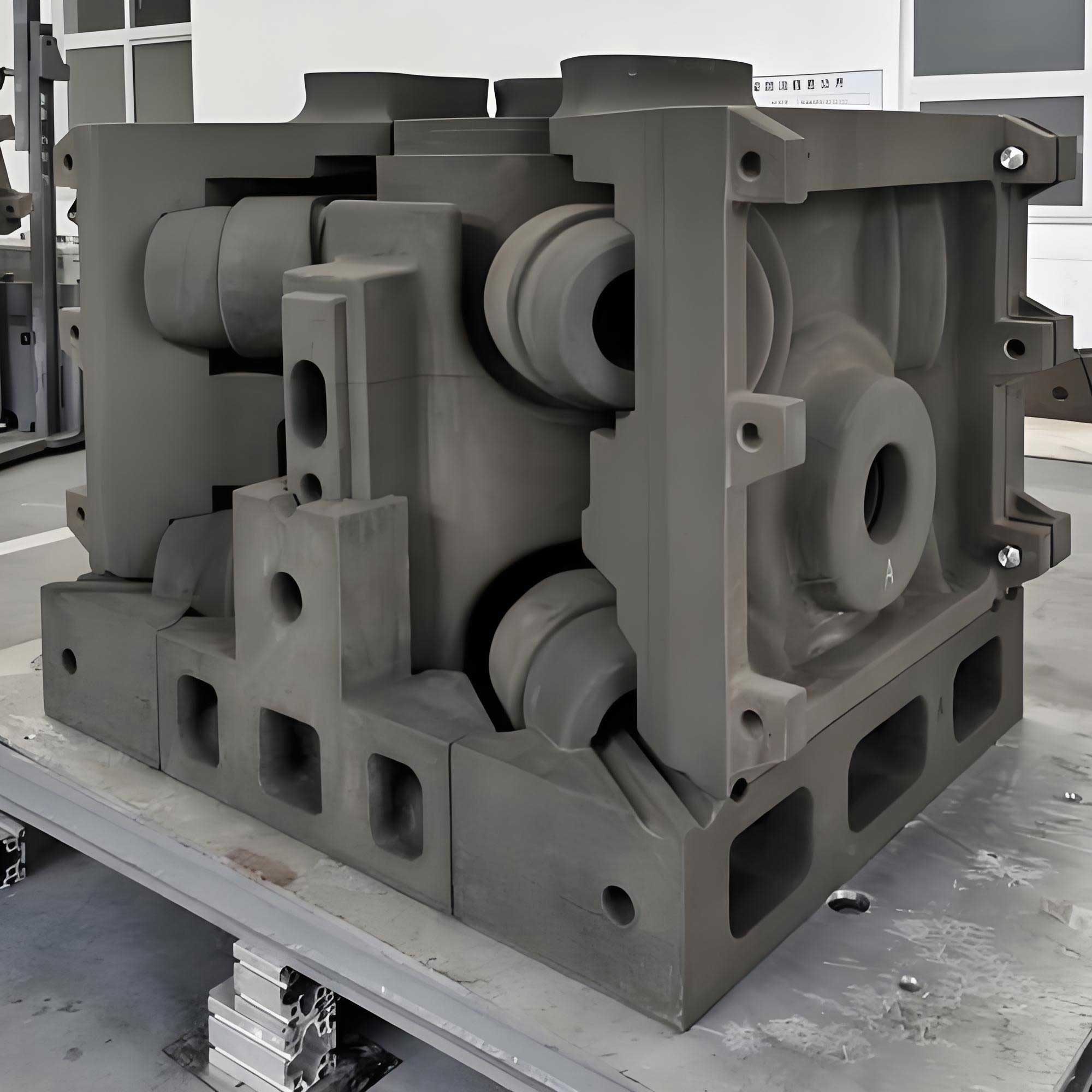
The figure included in this thesis illustrates a typical 3D printed sand mold used in my experiments. Such molds are produced layer-by-layer using binder jetting technology, and their surface quality is sufficient for direct mounting of the heat recovery device.
7 Conclusion and Future Work
In this thesis, I have presented a comprehensive study on the recovery of waste heat from the surface of 3D printed sand molds during the cooling stage of sand casting. The main contributions of my work are as follows:
- I proposed a novel waste heat recovery method based on thermoelectric generation, specifically tailored for 3d printing sand casting. The method includes the design of a compact, low-maintenance recovery device and a systematic placement strategy.
- I developed a prediction model for the total recovered electrical energy using a thermal resistance network and the Seebeck effect. The model was validated through small-scale and industrial-scale experiments, achieving an average accuracy of 92.2%.
- I demonstrated that the internal structure of the sand mold has a profound influence on the heat recovery efficiency. By comparing several structures (dense, truss, rib, porous, hollow), I found that the truss lattice structure is the most effective. I then proposed an optimized sand mold design methodology that incorporates flat recovery platforms and interference-free truss supports, resulting in a 45%–70% increase in recovered energy and a 40%–50% reduction in cooling time.
These outcomes are directly applicable to the foundry industry, where 3d printing sand casting is increasingly adopted. Recovering waste heat not only reduces the overall energy consumption of the casting process but also provides a source of clean electricity that can be stored or used for ancillary operations. Future research directions include: (1) optimizing the design of the recovery device itself, for example, by embedding heat pipes or using phase change materials to improve heat collection; (2) developing energy storage or direct utilization systems for the recovered electricity, such as powering fans for forced cooling or charging sensors; and (3) designing modular thermoelectric recovery units that can be easily scaled and adapted to sand molds of various shapes and sizes. I believe that the integration of thermoelectric generation with 3d printing sand casting will become a key enabler for green and sustainable casting production.