
As a graduate student focusing on mechanical engineering, I have spent substantial time investigating advanced casting techniques that can address the inherent limitations of conventional resin sand casting when producing complex pump impellers. The present dissertation summarizes my research on applying lost foam casting to the production of high-chromium alloy pump impellers. Through a combination of process analysis, dedicated tooling design, numerical control machining trials, white zone and black zone experiments, and iterative casting parameter optimization, I have demonstrated that lost foam casting offers significant advantages in dimensional accuracy, surface quality, and production efficiency for this challenging component geometry.
1. Introduction and Background
Lost foam casting is regarded as one of the most promising green casting technologies in the 21st century. It combines the principles of full mold casting with vacuum sealed sand molding, resulting in near-net-shape castings with excellent surface finish and minimal machining allowances. In my research, I recognized that traditional resin sand casting for pump impellers suffers from several drawbacks: complicated core assembly, high labor intensity, difficulty in pattern withdrawal, large machining allowances, and inconsistent dimensional stability. These problems are particularly acute for impellers with twisted blades and narrow flow channels. The motivation behind this study was to develop a reliable lost foam casting process specifically for high-chromium white iron pump impellers, which are widely used in slurry pumps and desulfurization pumps.
The global development of lost foam casting began with its invention in the United States and its subsequent industrialization in Germany through vacuum sealed molding. Over the past five decades, industrial countries have built highly automated lost foam casting lines for automotive engine blocks, cylinder heads, and complex pipe fittings. In China, the technology gained momentum only in the last decade, with companies such as gear manufacturers and foundry equipment suppliers adopting the process for medium-to-large castings. However, the application of lost foam casting to high-chromium alloy pump impellers has not been widely reported, mainly because of the material’s poor fluidity, high solidification shrinkage, and tendency to crack. My research aimed to bridge this gap by systematically designing the entire process chain: from three-dimensional modeling, mold design, CNC machining, foam pattern production, coating, and finally casting trials.
The significance of this research lies not only in improving the quality of pump impellers but also in promoting energy saving and environmental protection. Lost foam casting eliminates the need for chemical binders in sand, and the sand reclamation rate exceeds 95%. The process also reduces the number of manufacturing steps compared to resin sand casting. By replacing traditional methods with lost foam casting, manufacturers can achieve cleaner workshops, lower production costs, and better working conditions. The findings of this study provide practical guidance for pump manufacturers seeking to upgrade their casting capabilities.
2. Feasibility Analysis of Lost Foam Casting for Pump Impellers
2.1 Material Characteristics of High-Chromium Iron
The pump impeller material investigated in this study is a self-developed high-chromium alloy, referred to as GLCr-1. Its chemical composition is presented in Table 1.
| Element | C | Si | Mn | Cr | Ni | Mo |
|---|---|---|---|---|---|---|
| Content (wt%) | 1.5–2.8 | ≤0.6 | ≤1.2 | 20–35 | 0–5 | 0–4 |
The mechanical properties after heat treatment are listed in Table 2.
| Property | Bending strength (MPa) | Impact toughness (J/cm²) | Tensile strength (MPa) | Hardness (HRC) |
|---|---|---|---|---|
| Value | ≥700 | ≥8 | ≥350 | 58–65 |
This high-chromium alloy exhibits excellent abrasion resistance and corrosion resistance, but its casting characteristics are poor. The wide solidification temperature range promotes a pasty solidification mode, leading to significant shrinkage porosity and hot tearing tendency. Moreover, the alloy has low thermal conductivity and high brittleness, making it highly prone to cold cracking. Therefore, any casting process applied to this material must carefully control thermal gradients, feeding, and the rigidity of the mold.
When considering lost foam casting for such an alloy, several challenges arise. The decomposition products of the foam pattern (mainly gas and carbon) must be efficiently evacuated from the mold cavity, otherwise they can cause pores and carburization defects. The vacuum system must maintain sufficient negative pressure to compact the dry sand and support the mold wall during pouring. The coating must be strong enough to resist the erosion of molten metal and permeable enough to allow gas escape. In my research, I addressed these challenges by tailoring the coating composition, optimizing the negative pressure range, and designing a robust gating system.
2.2 Comparison with V-Process Casting
Both lost foam casting and V-process casting are vacuum-assisted dry sand processes that share several similarities: they both require vacuum pumps, coatings, and dry unbonded sand. However, critical differences exist regarding pattern and mold construction. In V-process casting, a plastic film is vacuum formed over a pattern, and the cavity remains empty after pattern removal. The molten metal directly fills the cavity, and the vacuum is maintained through vent holes connected to the film. In lost foam casting, the foam pattern remains inside the mold and vaporizes upon contact with the molten metal. The gas must permeate through the coating and sand by the vacuum draw. This fundamental difference affects the gas evolution behavior and the risk of defects.
For pump impellers with complex internal channels and twisted blades, V-process casting would require separate core boxes and multi-part patterns, which increases tooling cost and assembly complexity. Lost foam casting allows the production of a one-piece pattern (assembled from several foam segments), eliminating the need for cores and resulting in better coaxiality and wall thickness uniformity. Consequently, I concluded that lost foam casting is superior to V-process for this specific component. Table 3 summarizes the comparison.
| Aspect | Lost Foam Casting | V-Process Casting |
|---|---|---|
| Pattern type | Consumable foam pattern | Reusable pattern + plastic film |
| Core requirement | No cores required | Often requires cores for complex internal passages |
| Mold cavity | Filled with foam pattern | Empty cavity |
| Gas evacuation | Through coating and sand by vacuum | Through vent holes and film |
| Tooling complexity | Simpler for integral impeller | More complex due to core boxes |
| Dimensional repeatability | Excellent | Good, but affected by film |
| Application suitability | Best for complex integral castings | Better for medium/large simple shapes |
Based on this analysis, I selected lost foam casting as the primary process for the pump impeller project.
2.3 Technical Process Route
The overall technical route for implementing lost foam casting in pump impeller production is shown in Figure 1. This route includes product selection, foam pattern design, mold design and CNC machining, foam pattern manufacturing, coating, sand filling, pouring, and post-processing. The route emphasizes iterative optimization: after each trial casting, defects are analyzed, parameters are adjusted, and the process is refined until stable production is achieved.
I adopted a step-by-step strategy. First, I selected a high-demand impeller model as the pilot product. Second, I designed and manufactured the necessary tooling. Third, I conducted single-piece trials to verify process parameters. Fourth, after achieving three consecutive qualified castings, I expanded to batch production. Finally, I standardized the process based on three successful batches. This incremental approach minimized risk and allowed systematic learning.
3. Tooling Design and CNC Manufacturing of the Lost Foam Mold
3.1 Mold Material Selection
The lost foam mold must repeatedly endure heating and cooling cycles while being exposed to steam and water. It must have high thermal conductivity, corrosion resistance, sufficient strength to withstand steam pressure, and dimensional stability. Based on these requirements, I selected cast aluminum alloy ZL104 with a modification treatment during melting. This material offers low density, good machinability, excellent thermal conductivity, and adequate mechanical properties, making it both cost-effective and reliable for lost foam tooling.
3.2 Impeller Geometry and Mold Structure
The pump impeller under study has a diameter exceeding 500 mm, twisted blades, and narrow flow passages. The blades merge with the front and back shrouds through fillets. A one-piece mold would be impossible to strip because the twisted blades create undercuts. Therefore, I adopted a segmented mold design: the impeller pattern is divided into two halves at the shroud-blade junction plane. Each half is molded separately and then bonded together using locating features. Within each half, the blade areas are made as loose pieces (slides) that remain with the foam pattern during ejection and are then returned to the mold for the next cycle. This approach, common in lost foam tooling, allows the pattern to be removed without damage.
Figure 2 shows the loose piece for an impeller blade. The blade insert is a thin twisted plate with thickness normally less than 10 mm. Its machining requires careful planning of clamping and support. I designed auxiliary machining allowances to be removed after CNC machining.
The hub area of the impeller is thick and prone to incomplete fusion during foam molding. To ensure uniform expansion, I designed a specially vented loose piece in the hub region, equipped with multiple air vents. Figure 3 illustrates the hub venting block.
To increase productivity, I placed both the front and back halves of the same impeller in one mold base, producing two foam halves per cycle. The two cavities are separated by a central plate, and each cavity has its own injection and venting system. This two-cavity arrangement reduces handling and ensures that both halves are made under identical conditions, minimizing dimensional mismatch during assembly.
The final mold structure is shown in Figure 4. It includes the upper cavity for the front shroud half and the lower cavity for the back shroud half. Dovetail slides hold the blade loose pieces in position. Locating pins and bushings ensure that the two mold halves align correctly when the mold is closed. A sealing groove on the parting surface accommodates a high-temperature silicone seal.
3.3 CNC Machines Used for Tooling Production
Because the impeller blades have complex free-form surfaces, conventional machining methods cannot achieve the required precision. I utilized three types of CNC machines:
- CNC engraving and milling machine: with a work envelope of 3000×2000×800 mm and a maximum spindle speed of 12000 rpm. This machine was used to machine the EPS foam master patterns for the mold cavities.
- CNC gantry milling machine: a three-axis simultaneous machining center used for aluminum mold plates and core inserts. It offers high rigidity and accuracy.
- CNC vertical machining center: used for smaller components such as blade inserts and venting blocks, with a work envelope of 800×500×500 mm.
- CNC wire-cut EDM machine: used for cutting simple shaped plates and for finishing the thin blade inserts that cannot be easily milled.
The processing workflow begins with geometric analysis of the 3D model, followed by tool path generation in CAM software, post-processing to NC code, then simulation and verification. After machining, each component is inspected using CMM and surface roughness testers.
3.4 Cutting Parameters Optimization
I conducted a systematic study of cutting parameters for machining ZL104 aluminum mold parts using carbide tools. A reference table from the tool manufacturer is shown in Table 4.
| Tool type | Workpiece material | Cutting speed V (m/min) | Feed per tooth fz (mm/z) | Depth of cut ap (mm) | Width of cut aw (mm) |
|---|---|---|---|---|---|
| Solid carbide end mill | Steel HB180-280 | 90-160 | 0.01-0.30 | ≤D | ≤0.2D |
| Solid carbide end mill | Cast iron HB180-220 | 100-150 | 0.01-0.30 | ≤D | ≤0.2D |
| Ball nose end mill | Steel HB180-280 | 80-220 | 0.01-0.08 | ≤0.4D | ≤D |
| Ball nose end mill | Cast iron HB180-220 | 230-280 | 0.02-0.10 | ≤0.4D | ≤D |
For the aluminum mold material, I selected a cutting speed of 150 m/min as a compromise between tool life and surface finish. The spindle speed was calculated using the following formula:
$$ n = \frac{1000 V_c}{\pi D_c} \tag{1} $$
where \( n \) is the spindle speed in rpm, \( V_c \) is the cutting speed in m/min, and \( D_c \) is the cutter diameter in mm. For a 12 mm diameter end mill, the spindle speed becomes:
$$ n = \frac{1000 \times 150}{\pi \times 12} \approx 3979 \text{ rpm} \tag{2} $$
I set the spindle speed to 4000 rpm. The feed rate was calculated using:
$$ V_f = f_z \cdot n \cdot Z \tag{3} $$
where \( Z \) is the number of teeth. For a three-flute cutter and \( f_z \) between 0.05 and 0.2 mm/z, the feed rate range is:
$$ V_f = 0.05 \times 4000 \times 3 = 600 \text{ mm/min} \tag{4} $$
to
$$ V_f = 0.2 \times 4000 \times 3 = 2400 \text{ mm/min} \tag{5} $$
I chose 2000 mm/min for roughing and 1200 mm/min for finishing to balance productivity and surface quality. These parameters were stored in the CAM template and consistently applied for subsequent mold components.
3.5 Mold Assembly
After machining, the mold sections were assembled. The key steps included:
Installation of air vents: I used aluminum vent plugs of 8 mm and 6 mm diameters. These plugs were press-fitted into stepped holes drilled from the back side of the mold. Vent placement was spaced approximately 40 mm on large flat surfaces, with closer spacing in corners and thin sections. Correct vent placement ensures uniform filling of the foam beads and efficient steam heating and cooling.
Injection holes: The injection tube (sprue) was positioned on the thick shroud areas to facilitate complete filling of the beads. The filling plug was designed to match the cavity contour after installation. After each fill, the plug is locked to prevent bead leakage.
Loose piece assembly: The blade inserts and hub vent blocks were assembled using stainless steel screws from the non-cavity side. This allowed easy replacement of worn inserts without affecting the cavity shape.
Sealing: A U-shaped hollow silicone seal was installed in the parting line groove. This seal proved superior to ordinary O-rings because it resisted high-temperature aging and maintained elasticity after repeated cycling.
3.6 Special Sand Box
I designed two sizes of dedicated vacuum sand boxes: 1200×1200×1300 mm and 1200×1500×1600 mm. These boxes are made of welded steel profiles with a double-wall structure. The inner wall is perforated and covered with a 100-mesh stainless steel screen to allow vacuum draw while preventing sand escape. The sand box structure provides high rigidity and even vacuum distribution, which is critical for avoiding mold collapse during pouring.
4. White Zone Production Trials
The white zone in lost foam casting involves the production of foam patterns from expandable polystyrene (EPS). The key equipment includes the pre-expander, the foam molding machine, and the drying oven. I evaluated both steam-heated and electric-heated pre-expanders.
4.1 EPS Pre-expansion
The goal of pre-expansion is to obtain pre-expanded beads with a bulk density of 22–24 g/L and uniform particle size. I tested two heating methods: steam and electric. Table 5 summarizes the process parameters.
| Heating method | Preheat temperature | Steam pressure | Expansion temperature | Heating time | Holding time | Density (g/L) |
|---|---|---|---|---|---|---|
| Steam | 80–85°C | 0.05–0.1 MPa | 85–95°C | 200–300 s | 5 s | 22–24 |
| Electric | 80–85°C | – | 85–95°C | 250 s | – | 22–24 |
I found that electric heating vacuum pre-expansion produced more uniform beads with lower moisture content and fewer unexpanded particles. Therefore, I adopted the electric method for production. After pre-expansion, the beads were dried and aged for at least 24 hours before use.
4.2 Foam Pattern Molding
The pre-expanded beads are then filled into the mold cavity and heated again by steam to fuse together. The mold is first preheated to 40–60°C. Using pressurized filling, the beads are injected into the cavity. The steam pressure in the mold chamber is set between 0.1 and 0.12 MPa, with thinner sections using the lower value and thicker sections the higher value. The heating time is adjusted based on the pattern wall thickness to achieve a smooth surface without unfused beads.
After fusion, the pattern is cooled by circulating water through the mold cooling channels. The pattern is then ejected gently using ejector pins. I observed that the moisture content of the as-molded pattern is high; therefore, drying is essential before assembly and coating. The drying stage is critical to prevent dimension changes and internal voids.
4.3 Pattern Drying
I evaluated several drying technologies including hot air resistance heating and steam coil heating. Considering the plant infrastructure, I selected a circulating hot air drying system combined with a gas-fired steam boiler. The drying room maintained temperature at 40–60°C and the patterns were dried for at least 48 hours. Sufficient drying reduced the moisture content below 1%. The drying racks were designed to support the patterns without causing deformation. I used dehumidifiers to control the relative humidity and steam coils to maintain temperature. The system proved efficient and stable, with uniform temperature distribution throughout the drying chamber.
4.4 Pattern Assembly and Bonding
Because the impeller pattern is split into two halves, I needed to bond them accurately. I used hot melt adhesive for the core and cold glue for large planar surfaces. The bonding process involved:
1. Cleaning the bonding surfaces with a soft brush.
2. Applying a thin layer of hot melt glue or cold glue evenly.
3. Pressing the halves together using a fixture that ensures alignment.
4. Allowing the assembly to cure for at least 10 minutes before moving to the drying room.
Right-angle clamps and locating pins were used to maintain the correct relative position. The bonded pattern was inspected for gaps. Minor surface defects were repaired using a foam repair paste.
4.5 Coating Technology
The coating is one of the most critical factors in lost foam casting. It must provide high temperature strength to prevent sand erosion, sufficient permeability to allow gas escape, and adequate room temperature strength to prevent pattern damage during handling and sand filling.
I used a commercial refractory coating formulated for ferrous castings. The mixing procedure was as follows:
1. Weigh water equal to approximately 70% of the coating powder weight.
2. Add the coating powder to the water slowly while stirring.
3. Stir at 400 rpm for 1 hour, then at 200 rpm for 20 minutes.
4. Measure the Baume degree of the slurry using a hydrometer; the target is 1.7–1.8 Be. Adjust with water or powder if necessary.
The coating was applied by dipping. The foam pattern was fully immersed in the slurry and then withdrawn to allow excess slurry to drain. After the first coat, the pattern was placed on a drying rack and sent to the drying room. The process was repeated for a second and sometimes a third coat. The final coating thickness was controlled between 1.2 and 1.5 mm for the main surfaces and 2–3 mm for the gating system. The coating had to be uniform, without bare spots or cracks. After coating, the patterns were analyzed for any defects.
5. Black Zone Production Trials
The black zone refers to the sand molding, pouring, and casting operations. I defined the process parameters based on calculations, then verified through simulation and production trials.
5.1 Determination of Shrinkage Allowance
The casting shrinkage of high-chromium iron is affected by several factors, including alloy composition, mold rigidity, negative pressure, and pattern contraction. Initially, I set the shrinkage rate to 2% based on the resin sand process. However, after measuring the first trial castings, I found that some areas lacked machinable allowance. By measuring multiple castings, I concluded that the total shrinkage allowance should be 3%, which includes approximately 2% for alloy solidification and 1% for foam pattern shrinkage and deformation.
5.2 Machining Allowance
Lost foam casting achieves high dimensional accuracy, permitting smaller machining allowances than resin sand casting. Based on the impeller diameter (greater than 500 mm) and referencing standard recommendations, I selected a machining allowance of 6 mm per side for the outer profile and 2 mm for surfaces requiring tool indication marks.
5.3 Parting Surface and Pouring Position
The parting surface was chosen along the water passage edge of the impeller to simplify mold manufacturing and pattern assembly. This orientation facilitates the positioning of the pattern cluster in the sand box and ensures straightforward sand filling.
5.4 Gating System Design
The gating system must control metal flow, fill the cavity quickly, prevent gas entrapment, and provide good slag separation. I chose a top-pour closed gating system for the initial trials. Using the casting simulation software, I calculated the required cross-sectional areas.
For a 180 kg impeller, the initial total ingate area was determined from the casting handbook as 10 cm². I used four ingates, each with a trapezoidal cross-section. The area ratio for the closed system was:
$$ F_{\text{inner}} : F_{\text{runner}} : F_{\text{sprue}} = 1.0 : 1.2 : 1.4 \tag{6} $$
Therefore, the runner area was \(10 \times 1.2 = 12\) cm² and the sprue area was \(10 \times 1.4 = 14\) cm². To account for the gas absorption and heat loss in lost foam casting, I increased all areas by 20%. The final dimensions were:
- Ingate: 24 × 19 × 17 mm (four ingates, total area 12 cm²)
- Runner: 40 × 30 × 42 mm (total area 14.4 cm²)
- Sprue: 70 mm diameter (total area 16.8 cm²)
The pouring time was calculated as:
$$ t = \frac{\text{total metal weight}}{\text{filling rate}} = \frac{280\text{ kg}}{20\text{ kg/s}} = 14\text{ s} \tag{7} $$
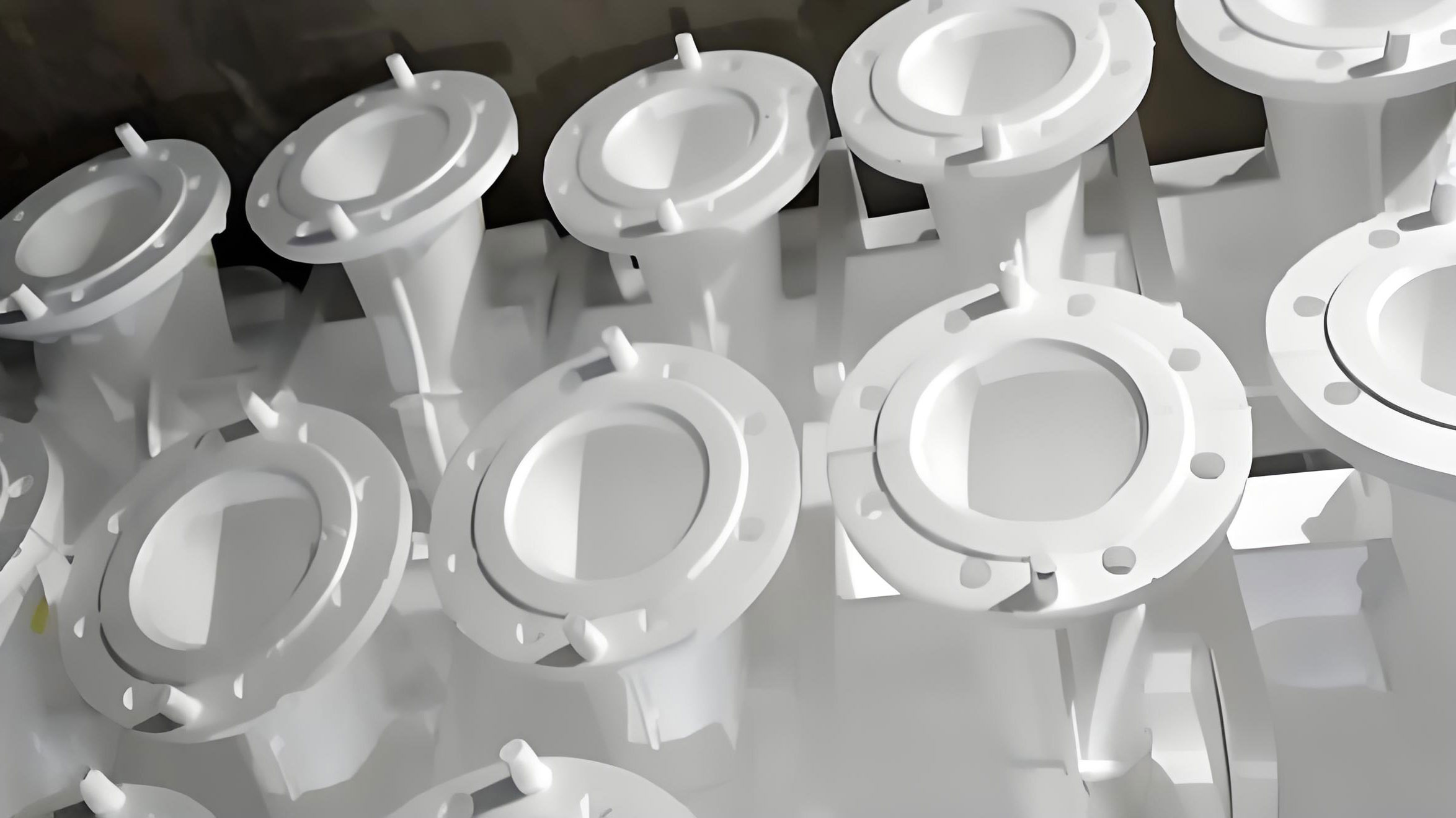
The gating system components were themselves made of foam using the same molding process, as illustrated in the process photos.
5.5 Riser Design
Risers are needed to compensate for liquid and solidification shrinkage. I selected side blind risers placed on the hub (the thickest section) to ensure efficient feeding. According to the modulus method, the relationship between the casting modulus \( M_{\text{part}} \), the neck modulus \( M_{\text{neck}} \), and the riser modulus \( M_{\text{riser}} \) is:
$$ M_{\text{part}} : M_{\text{neck}} : M_{\text{riser}} = 1 : 1.1 : 2 \tag{8} $$
The hot spot at the hub was 90 mm thick, so the neck diameter was set to \(90 \times 1.1 = 100\) mm and the riser diameter to \(90 \times 2 = 180\) mm. The riser height was set to \(180 \times 3 = 540\) mm.
To verify the riser capacity, I used the following inequality:
$$ V_{\text{riser}} \eta \ge \varepsilon (V_{\text{part}} + V_{\text{riser}}) \tag{9} $$
where \( \varepsilon \) is the total contraction (3%), \( \eta \) is the riser efficiency (30% for a blind riser), and \( V \) represents volumes. Substituting the calculated volumes from the three-dimensional model:
$$ 0.3 \times 13,741,326 \text{ mm}^3 \ge 0.03 \times (13,741,326 + 23,128,069) \text{ mm}^3 \tag{10} $$
The left side was 4,122,398 mm³ and the right side was 1,106,081 mm³, so the riser capacity was sufficient.
5.6 Pouring Temperature
Because the decomposition of the foam pattern is an endothermic process that absorbs heat, and the vacuum also extracts heat, the pouring temperature in lost foam casting should be higher than in conventional sand casting. For high-chromium iron, which behaves similarly to ductile iron but with a higher melting point, I selected a pouring temperature range of 1400–1470°C. This range ensures good fluidity and complete gas evacuation.
5.7 Negative Pressure (Vacuum) Parameters
The applied vacuum compacts the dry sand, helps evacuate gases, and improves the surface finish of the casting. The recommended vacuum range for iron castings is 300–400 kPa. During the trials, I set the vacuum at 350 kPa. Too high a vacuum can cause sand penetration; too low can lead to mold collapse. I maintained the vacuum during pouring and continued it for several minutes after pouring until the casting solidified.
6. Casting Trials and Process Improvement
6.1 Initial Trial Results
Using the initial top-pour gating with the parameters in Table 6, I conducted a trial production run.
| Parameter | Value | Remarks |
|---|---|---|
| Casting shrinkage | 3% | Total allowance |
| Machining allowance | 6 mm | Per side |
| Ingate size | 24×19×17 mm | 4 ingates |
| Runner size | 40×30×42 mm | – |
| Sprue diameter | Φ70 mm | – |
| Total metal weight | 280 kg | Including gating |
| Pouring time | 14 s | – |
| Riser neck | Φ100 mm | Blind side riser |
| Riser body | Φ180 mm | One riser feeds three hot spots |
| Riser height | 540 mm | – |
| Vent hole | Φ30 mm | Top vent |
The castings exhibited severe shrinkage and gas porosity at the hub area, as shown in the defect photographs. The analysis revealed that the top-pour configuration caused turbulent filling and early vacuum breakthrough at the riser, leading to insufficient feeding of the hub section. The riser neck was too small for proper gas evacuation.
6.2 Improved Gating System
I redesigned the gating system to a side-pour configuration, which is known to reduce turbulence and promote favorable temperature gradients. The modified layout is shown in the process diagram. To ensure the new design was effective, I performed a casting process simulation (using ProCAST-like software). The simulation results indicated that the red (high defect) region was concentrated in the riser, while the blade areas showed only minor yellow defects, confirming acceptable soundness. The improved process eliminated the axis hole defects.
The final casting process is illustrated in Figure 10. The impeller pattern is placed in the sand box with the side gating attached. The complete assembly is coated and dried, then placed in the sand box, surrounded by dry silica sand, and compacted by vibration. After sealing the top with a plastic film and applying the vacuum, the molten metal is poured through the sprue. The foam pattern vaporizes ahead of the advancing metal front, creating the cavity. After solidification and cooling, the casting is shaken out and the sand is reclaimed.
7. Results and Discussion
Following the improved side-pour process, I produced a series of pump impellers. The machining of the hub area showed no shrinkage defects, confirming the effectiveness of the redesign. The surface quality of the impeller was significantly better than resin sand castings, with reduced machining time and cleaner finish.
The success of this research is attributed to the following key factors:
1. Accurate tooling: The CNC-machined aluminum mold with proper venting and loose pieces allowed the production of precise foam patterns.
2. Optimized foam molding process: Controlled pre-expansion and steam fusion resulted in uniform density and minimal internal defects.
3. Robust coating: The refractory coating provided imperviousness to erosion while allowing gas escape.
4. Proper gating and risering: The side-pour gating with adequate riser size ensured sound feeding.
5. Vacuum control: The 350 kPa vacuum maintained mold stability and facilitated gas removal.
Through repeated trials, I established a set of production parameters that can be used as a reference for other impeller sizes. Table 7 summarizes the optimized parameters for the pilot impeller.
| Parameter | Optimized value |
|---|---|
| Casting shrinkage | 3% |
| Machining allowance | 6 mm (per side) |
| Gating system | Side-pour, closed |
| Ingate area | 12 cm² (4 ingates) |
| Runner area | 14.4 cm² |
| Sprue area | 16.8 cm² |
| Riser type | Blind side riser, Φ180×540 mm |
| Pouring temperature | 1400–1470°C |
| Negative pressure | 300–400 kPa |
| Coating thickness | 1.2–1.5 mm |
| Pattern drying | 48 h at 40–60°C |
8. Conclusion
In this thesis, I systematically investigated the application of lost foam casting to high-chromium alloy pump impellers. The main conclusions are as follows:
1. Lost foam casting is technically feasible and advantageous for pump impellers compared to resin sand casting and V-process casting. It eliminates cores, reduces machining allowances, improves structural consistency, and creates a cleaner working environment.
2. A segmented mold design with loose blade inserts and a vented hub block successfully enables the production of complex twisted impeller patterns. The use of aluminum ZL104 with proper venting and sealing was validated through production trials.
3. CNC machining with optimized cutting parameters (spindle speed 4000 rpm, feed 2000 mm/min) enables high-precision fabrication of impeller lost foam molds, achieving the required dimensional accuracy and surface finish.
4. The white zone process parameters, including electric vacuum pre-expansion, exact steam fusion conditions, and a rigorous drying procedure, ensure high-quality foam patterns with uniform density and low moisture content.
5. The black zone process parameters, particularly the side-pour closed gating system and blind side riser, eliminate the hub shrinkage defects encountered with the initial top-pour configuration. The optimized casting parameters (3% total shrinkage, 6 mm machining allowance, pouring temperature 1400–1470°C, negative pressure 300–400 kPa) produce sound castings with good internal quality.
6. The research provides a practical technical route and design guidelines for pump manufacturers to implement lost foam casting for impellers, thereby improving product quality, reducing cost, and supporting sustainable development.
The implementation of lost foam casting in my company has already yielded large batches of qualified pump impellers, significantly enhancing competitiveness and contributing to cleaner production. Future work will focus on extending this process to larger impellers and exploring the use of other foam materials such as copolymer beads to further reduce defects.