
My research focuses on the numerical simulation technology of thermal stress fields during the sand casting foundry process. The solidification of molten metal in a sand casting foundry is a complex thermo-mechanical phenomenon that involves transient heat transfer, phase transformation, and the development of internal stresses due to non-uniform cooling. The primary objective of my work is to establish a reliable and practical methodology for predicting residual stresses, deformation, and potential hot tearing in castings produced by the sand casting foundry method. The use of numerical simulation for the sand casting foundry process has become increasingly critical as the industry demands higher dimensional accuracy and mechanical performance from cast components. This research provides a comprehensive framework based on the finite element method (FEM), leveraging the ANSYS software package to conduct sequential thermal-stress analysis. This approach enables a detailed understanding of the dynamic evolution of thermal stresses, which is essential for optimizing the sand casting foundry process parameters. In this article, I will detail the theoretical foundations, the development of the mathematical models, and the application of these models to both a benchmark casting geometry and a real industrial component.
1. Introduction and research background
Over the past two decades, the sand casting foundry industry has undergone a significant transformation, moving from reliance on empirical rules to the application of scientific computing for process design. The need for numerical simulation is driven by the increasing complexity of castings and the demand for reduced development cycles and costs. While temperature field and fluid flow simulations have matured, the simulation of stress/strain fields remains a challenge due to the high degree of material non-linearity and the requirement for thermo-physical property data at elevated temperatures. My research is dedicated to addressing these challenges. The sand casting foundry environment presents unique conditions, such as the interaction between the solidifying casting and the sand mold, which has a relatively low strength but high thermal resistance. The thermal gradient within the casting causes differential contraction, leading to thermal stresses. If these stresses exceed the material’s yield strength, inelastic deformation and residual stresses will occur after cooling to ambient temperature. Residual stresses in a sand casting foundry product can cause dimensional instability, reduced fatigue life, and increased susceptibility to stress corrosion cracking. Therefore, accurately predicting these stresses is an important part of ensuring the reliability of castings.
The technical roadmap of my study is based on a sequentially coupled analysis. Unlike fully coupled approaches, this method calculates the transient temperature field first, then applies the temperature history as a thermal load in a subsequent structural analysis. This is a common but effective strategy when the mechanical work generated by deformation does not significantly influence the thermal field. In the context of the sand casting foundry, the solidification process is relatively slow, so this simplification is reasonable. This approach is computationally cheaper and allows the use of specialized solvers for each analysis stage. The methodology involves several steps: designing the 3D model, meshing the solid and mold domains, defining temperature-dependent material properties, applying initial and boundary conditions, solving for the thermal field, and then loading the structure with the thermal results. The following sections will elaborate on each of these stages and the underlying theory.
2. Theoretical fundamentals and literature review
The simulation of the sand casting foundry stress involves the application of continuum mechanics to describe the mechanical behavior during cooling. Work in this area began relatively late compared to thermal analysis. Early models used simple elastic or pure plasticity assumptions, which were not sufficient to capture the complex behavior of materials at high temperatures. Contemporary approaches use the thermal elastic-plastic (or elasto-viscoplastic) constitutive law to model the deformation. In my research, I employ the thermal elastic-plastic model, which has been widely accepted as being accurate enough for predicting residual stress. The mechanical behavior includes several critical features: the temperature dependence of material properties, the transition from elastic to plastic state, and the effect of phase transformations such as the eutectoid pearlite transformation in carbon steel castings. The thermal elastic-plastic model is built upon the classical incremental theory of plasticity, which incorporates yield criteria, flow rules, and hardening laws.
The theoretical model is grounded in the thermodynamics of irreversible processes. The total strain increment \( d\varepsilon_{ij} \) is partitioned into elastic (\( d\varepsilon_{ij}^{e} \)), plastic (\( d\varepsilon_{ij}^{p} \)), thermal (\( d\varepsilon_{ij}^{T} \)), and in some models creep (\( d\varepsilon_{ij}^{c} \)) components. However, for simplicity and given the lack of a comprehensive creep model, my work focuses on the sum of elastic, plastic, and thermal constituents:
\[
d\varepsilon_{ij}=d\varepsilon_{ij}^{e}+d\varepsilon_{ij}^{p}+d\varepsilon_{ij}^{T}
\tag{1}
\]
I implemented the V. Mises yield criterion to detect the onset of plastic deformation, a fundamental component of metal plasticity. The yield function is expressed in terms of the deviatoric stress tensor \( S_{ij} \) and the yield stress \( \sigma_{s} \), which is a function of temperature (\( T \)):
\[
F=\frac{1}{2}S_{ij}S_{ij}-\frac{\sigma_{s}^2}{3}=0
\tag{2}
\]
This criterion states that yielding begins when the von Mises equivalent stress equals the yield stress. For isotropic hardening, the yield surface expands uniformly as plastic deformation progresses. The hardening behavior is characterized by the plastic modulus \( H’ \), also a temperature-dependent parameter.
In the analysis of the sand casting foundry process, I have considered the following fundamental assumptions to simplify the mathematical model in my research:
1. The casting material is isotropic and homogeneous, with no initial internal stress.
2. The material obeys the Von Mises yield criterion and is strain-hardening.
3. The solidifying metal is an ideal elastic-plastic material at high temperatures.
4. The geometry deformation is small, allowing the use of linearized strain-displacement relations.
5. The thermo-physical and mechanical properties are functions of temperature.
2.1 Heat Conduction Equations
The initial and boundary conditions are crucial for the simulation. The specific boundary condition governs the interaction with the environment. Convection and radiation are the main heat transfer mechanisms between the sand mold and the ambient air. To simplify the radiation calculation, I incorporated the flux into a combined heat transfer coefficient \( h_{eff} \):
\[
q = h_{eff}(T_{s} – T_{f})
\tag{3}
\]
where \( T_{s} \) is the surface temperature and \( T_{f} \) is the far-field temperature. This method is efficient for modeling the sand casting foundry cooling phase. The initial condition assumes that the mold is at ambient temperature (25°C) and the metal is poured at 1670°C. Additionally, the interface between the casting and the sand mold is assumed to be perfectly bonded, implying no air gap. This contact condition provides continuity of temperature and flux across the boundary.
The transient thermal conduction within a solidifying body in the sand casting foundry is governed by the Fourier equation:
\[
\rho c_p \frac{\partial T}{\partial t} = \nabla \cdot (k \nabla T) + q_{B}
\tag{4}
\]
where \( \rho \) is the density, \( c_p \) is the specific heat, \( T \) is the temperature, \( t \) is the time, \( k \) is the thermal conductivity, and \( q_B \) is the internal heat generation rate, which accounts for the latent heat during solidification.
This equation is a parabolic partial differential equation. In the finite element method, the domain is discretized into elements, and the temperatures are computed at nodes. The internal heat generation due to the phase change from liquid to solid is handled effectively by the enthalpy method. The enthalpy (\( H \)) is defined as the integral of the product of density and effective specific heat with respect to temperature. The specific heat is modified over the solidification interval. The equation for enthalpy is:
\[
H(T) = \int_{0}^{T} C_e dT
\tag{5}
\]
where \( C_e \) is the apparent specific heat capacity (which includes the latent heat contribution). This approach avoids the explicit tracking of the solid/liquid interface and simplifies the numerical code base for the sand casting foundry process.
The finite element formulation results in a system of first-order differential equations in the time domain:
\[
[C] \frac{d\{T\}}{dt} + [K] \{T\} = \{F\}
\tag{6}
\]
where \( [C] \) is the heat capacity matrix, \( [K] \) is the conductivity matrix, \( \{T\} \) is the nodal temperature vector, and \( \{F\} \) is the heat flux vector. This system is integrated over time using a backward Euler scheme in ANSYS, which is unconditionally stable, allowing for large time steps while maintaining accuracy. This also allows me to efficiently simulate the long cooling times experienced in a sand casting foundry.
2.2 Mechanical constitutive model
Once the temperature field is resolved, the structural stress analysis can be performed. The incremental stress-strain relationship is established. The elastic strain increment is connected to the stress increment via the elastic stiffness matrix \( [D_e] \), which is temperature-dependent through the elastic modulus \( E(T) \). For the plastic region, the stress increment is related to the strain increment via the elastoplastic matrix \( [D_{ep}] \). The general incremental constitutive law is expressed as:
\[
\{\Delta \sigma\} = [D_{ep}] (\{\Delta \varepsilon\} – \{\Delta \varepsilon^{T}\})
\tag{7}
\]
where \( \{\Delta \varepsilon^{T} \} \) is the thermal strain increment, computed from the temperature change and the coefficient of thermal expansion \( \alpha(T) \). The matrix \( [D_{ep}] \) is derived from the yield function, the flow rule, and the hardening rule.
A critical point in computing thermal stresses is the treatment of the phase transformation. During cooling, if the material undergoes a solid-state phase transformation, such as austenite to pearlite in steel, there is a volume expansion. This expansion can counteract thermal contraction and profoundly modify the final residual stress distribution. In my approach for the sand casting foundry process, I have incorporated the effect of this phase transformation by adjusting the coefficient of thermal expansion. The effective expansion coefficient is modified during the transformation temperature range to reflect the net volume change. Using a modified \( \alpha(T) \) curve that incorporates the phase transformation expansion is a common and practical technique to account for this phenomenon in a sand casting foundry analysis.
The plastic flow rule, which determines the direction of the plastic strain increment, is based on the normality rule to the yield surface. In the standard associated plasticity, the flow potential is the same as the yield function. The plastic strain increment is proportional to the gradient of the yield function:
\[
\{\Delta \varepsilon_{p} \} = \lambda \left\{ \frac{\partial F}{\partial \sigma} \right\}
\tag{8}
\]
where \( \lambda \) is a positive scalar multiplier derived from the consistency condition. The total strain is partitioned into elastic and plastic parts, and the equilibrium equations are solved using the Newton-Raphson iteration method inside ANSYS.
The finite element structural equilibrium equation is:
\[
[K_{ep}] \{\Delta u\} = \{\Delta F_{th}\} + \{\Delta F_{m}\}
\tag{9}
\]
where \( [K_{ep}] \) is the tangent stiffness matrix, \( \{\Delta u\} \) is the displacement increment vector, \( \{\Delta F_{th}\} \) is the equivalent thermal load vector, and \( \{\Delta F_{m}\} \) is the mechanical load vector. This formulation enables the analysis of both the casting and the sand mold. For structural boundary conditions, the solidifying casting contracts and interacts with the mold. In the baseline model, I omit the frictional resistance and assume the mold is deforming freely. In a more advanced model, I have used contact elements to simulate the gap and the sticking interactions between the casting and the mold. However, for the standard analyses presented in this work, a free boundary condition is applied. This simplification gives a conservative estimate of the stress distribution, which is useful for identifying hot spots in the sand casting foundry product. The sand mold is meshed along with the casting and included in the stress analysis. This is done because the mold has a notable influence on the thermal field and can affect the deformation of the casting. Even if the mold does not impose a strong mechanical constraint, it acts as a heat sink and its temperature gradient contributes to the differential cooling. In the stress simulation, the sand mold is also given mechanical properties like a low elastic modulus and low yield strength, representing a material that can be compacted and does not provide a strong rigid constraint. This methodology is critical for simulating the actual stress state in the sand casting foundry workpiece.
3. Temperature field simulation in a sand casting foundry
To validate my numerical approach for the sand casting foundry process, I have selected the benchmark test case of the “stress frame.” This geometry is a classic design used to investigate thermal stresses because it has two bars of differing thickness: a thick bar and a thin bar. This design inevitably leads to a temperature difference and the creation of internal forces upon cooling. The stress frame represents a typical casting produced in a sand casting foundry. The finite element model is created using the ANSYS software. For the thermal analysis, I used the 3D 8-node solid thermal element SOLID70. This element is well-suited for transient thermal analysis and has a single degree of freedom: temperature. The mesh size for the casting was set to 8mm, ensuring good detail on the thin sections. The sand mold was meshed with elements of 20mm, focusing the computational effort on the workpiece. The dimensions of the sand mold were chosen to be large enough to represent a semi-infinite medium, minimizing the effect of the outer boundary.
The material properties for the ZG25 steel casting and the sand mold were defined. The thermal conductivity, density, and specific heat of the mold material used in the model are listed in Table 1.
| Parameter | Value |
|---|---|
| Thermal conductivity (W/m·°C) | 0.52 |
| Density (kg/m³) | 1630 |
| Specific Heat (J/kg·°C) | 1120 |
The thermal properties of the casting material ZG25 are highly temperature-dependent. The thermal conductivity, enthalpy, and specific heat are presented in Table 2. The enthalpy values, which include latent heat, are crucial for the solution to converge correctly.
| Temperature (°C) | Conductivity (W/m·°C) | Enthalpy (J/m³) | Specific Heat (kJ/kg·°C) |
|---|---|---|---|
| 25 | 62.5 | 0 | 0.287 |
| 1460 | 65.2 | 8.24E9 | 0.581 |
| 1520 | 58.2 | 1.05E10 | 0.586 |
| 1670 | 58.2 | 1.14E10 | 0.668 |
The procedure begins with the creation of the 3D model in Pro/Engineer, which is then imported into ANSYS. After defining the material properties in the pre-processor, the mesh is generated. The initial conditions are established by running a 0.01 second steady-state thermal analysis. This short calculation simulates the instantaneous filling process, setting the casting temperature to the pouring temperature and the sand mold at ambient temperature. This step ensures a more realistic initial temperature distribution for the subsequent transient analysis, especially at the interface between the casting and the mold. This is a distinct feature of my modeling of the sand casting foundry process.
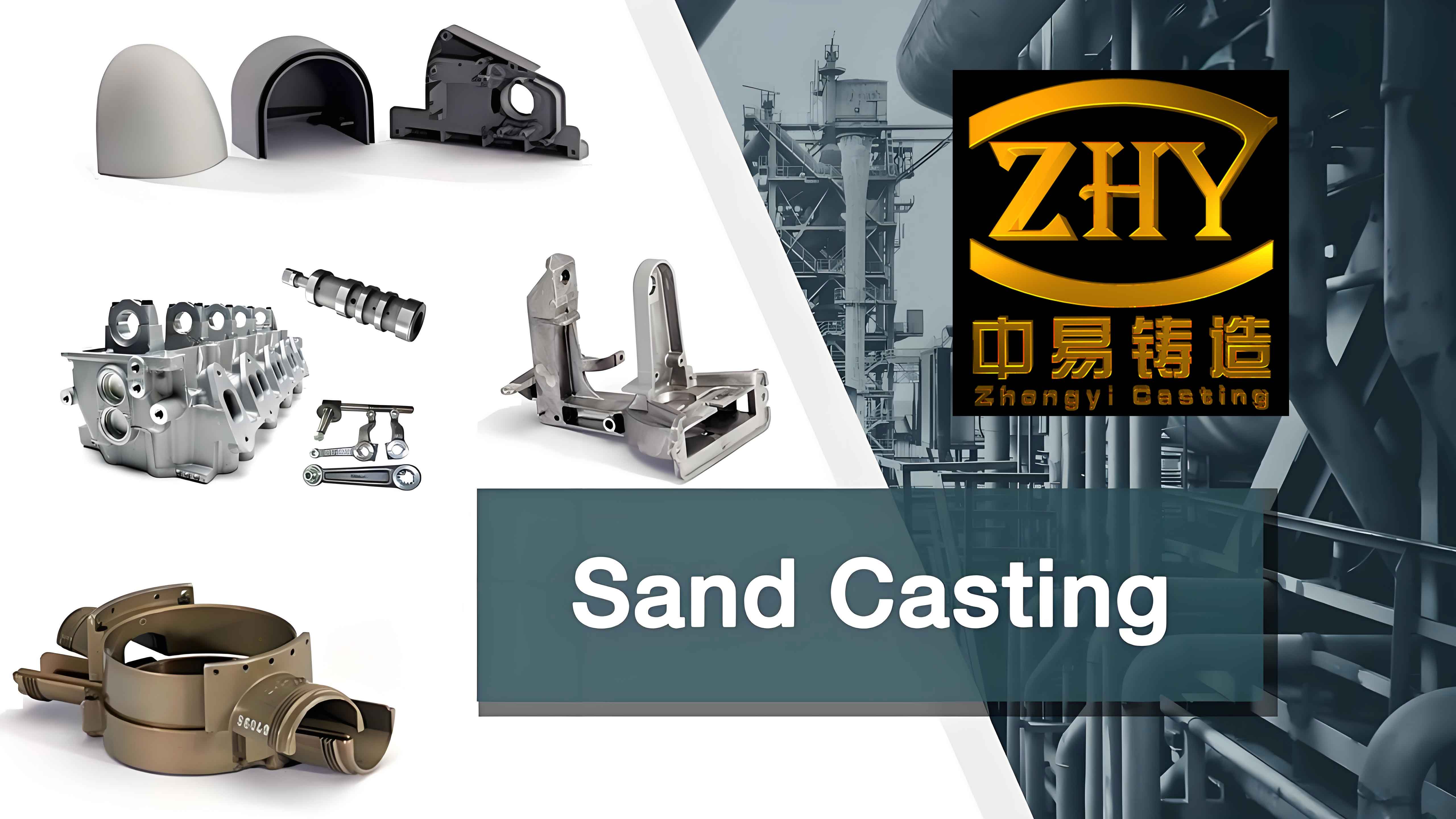
Figure 1 (the provided image link) illustrates a typical casting from a sand casting foundry showing the complexity of the geometries that can be handled by this simulation approach. The simulation then proceeds with a transient thermal analysis. The time step is set to 5 seconds initially, but is controlled by the program to maintain accuracy. The total cooling time is 6000 seconds. The simulation provides the temperature distribution at every node for each time step.
The results of the temperature field simulation for the stress frame reveal important behaviors. In the early stages (t=10s), the thin bars cool rapidly, and the thick bars remain at a high temperature. For example, at 10 seconds, the thin section temperature has dropped to around 1654°C, while the thick section is still at 1664°C. This temperature gradient is the root cause of the thermal stress generation. At 300 seconds, the thin bars have solidified and cooled significantly faster than the thick section. The thick section is still in the pasty zone (temperature between liquidus and solidus). The thermal contours show the hot spot located in the center of the thick bar. As cooling continues (t=600s and 800s), the thick bar begins to cool faster rate because heat is conducted away through the already solidified thin bars. This differential cooling behavior is a key characteristic of the sand casting foundry process and is the reason that a stress frame will distort if not constrained. By 1800 seconds, the temperature difference is much smaller. At 6000 seconds, the entire system has almost reached ambient temperature. The final temperature distribution shows a uniform room temperature across the casting, meaning that the thermal loading phase is complete, and the resulting residual stress field can be analyzed. The thermal gradient behavior is the primary driver for the development of residual stress, and my simulation has robustly captured this entire process.
4. Thermal stress field simulation in a sand casting foundry
Following the thermal analysis, the element type for the stress frame and the sand mold is changed from thermal (SOLID70) to structural (SOLID45). The structural element SOLID45 has three translational degrees of freedom per node. The temperature field results (files with a .rth extension) are then loaded as body forces. I used the indirect thermal-stress analysis method in ANSYS, which is a sequential approach. This approach is intuitive and avoids the high computational cost of a fully coupled analysis. In the sand casting foundry, the structural simulation of the casting uses the same finite element mesh as the thermal simulation, but with different material properties assigned, specifically the mechanical properties.
The high-temperature mechanical properties of ZG25 cast steel are essential for the accuracy of the stress simulation. These properties must be defined as a function of temperature. The data are listed in Table 3, Table 4, and Table 5 for elastic modulus, Poisson’s ratio, and thermal expansion coefficient. The table values reflect the degradation of strength and stiffness with increasing temperature. For example, the elastic modulus decreases from 184 GPa at room temperature to 0.048 GPa at 1400°C. This significant drop is typical for steels near their melting point. The yield stress also decreases from 240 MPa to 30 MPa in the same temperature range.
| Temperature (°C) | 25 | 200 | 400 | 600 | 800 | 1000 | 1200 | 1400 |
|---|---|---|---|---|---|---|---|---|
| Elastic Modulus (GPa) | 184 | 168 | 102 | 50 | 8.5 | 5.5 | 0.5 | 0.048 |
| Poisson’s Ratio | 0.278 | 0.303 | 0.310 | 0.327 | 0.344 | 0.36 | 0.377 | 0.39 |
| Temperature (°C) | 25 | 200 | 400 | 600 | 800 | 1000 | 1200 | 1400 |
|---|---|---|---|---|---|---|---|---|
| Expansion coefficient (1e-5/°C) | 1.4 | 1.5 | 1.6 | 1.7 | 1.8 | 2.0 | 2.2 | 2.3 |
| Temperature (°C) | 25 | 200 | 400 | 600 | 800 | 1000 | 1200 | 1400 |
|---|---|---|---|---|---|---|---|---|
| Yield strength (MPa) | 240 | 205 | 160 | 120 | 90 | 74 | 50 | 30 |
| Hardening modulus (GPa) | 5.2 | 4.8 | 4.2 | 3.1 | 1.2 | 0.26 | 0.008 | 0.0002 |
The stress analysis is highly nonlinear due to plasticity and temperature-dependent properties. To ensure convergence in the sand casting foundry numerical simulation, the Newton-Raphson method is employed. I also used the automatic time stepping feature, which adjusts the time increment based on the degree of nonlinearity. In the high temperature region, the material is modeled as an ideal plastic material with no hardening, which aligns with the physical reality that steel has very little work-hardening capacity at high temperatures. The treatment of the element at the transition from an elastic to a plastic state is also carefully addressed. A weighted average method is used to avoid sudden changes in the element stiffness.
The simulation of the stress frame produced results that are in good agreement with the physical understanding of sand casting foundry processes. At the initial stage of cooling, the thin bars are subjected to tensile stress, while the thick bars are under compressive stress. This is because the thin bars cool and contract faster than the center of the thick bar. The thick bar, still hot and plastic, is compressed by the contracting thin bars. The center of the thick bar experiences a state of biaxial compressive stress, while the thin bars are in a state of uniaxial tension. At t=1000 seconds, the thin bars exhibit a tensile stress of a certain magnitude, and the thick bar is in compression. As the cooling continues, the temperature gradient reverses. The thick bar begins to cool at a faster rate than the thin bars. This happens because the thin bars have already reached near-ambient temperatures, so their cooling rate decreases. The thick bar continues to lose heat, and its contraction is now constrained by the already rigid, cool thin bars. This leads to a reversal of the stress state. The thin bars go into compression, and the central section of the thick bar goes into tension. This stress reversal phenomenon is well-documented in the sand casting foundry literature and is the source of residual stress. In my simulation, this transition was observed to occur around t=1800-2500 seconds. At t=6000 seconds, the final residual stress state is established. The magnitude of the stress is lower than the maximum transient stress due to stress relaxation at high temperatures.
5. Application to an industrial seat casting
To demonstrate the engineering utility of the proposed method, I simulated the casting process of a “seat” component, which is a production part manufactured by a sand casting foundry. This seat has a maximum outer diameter of 820 mm and a height of 190 mm. The material is ZG30 steel, and the sand mold is made of self-hardening furan resin sand. The pouring temperature is 1670°C. The gating and riser systems are omitted from the model to simplify the analysis. The CAD geometry is imported and meshed with solid elements. Figure 2 shows the mesh of the seat. The goal is to predict the residual stress distribution and identify potential defect areas. The mold and casting are simulated together, as in the benchmark problem. The initial and boundary conditions are the same as before. The temperature field simulation for this larger casting shows a similar pattern. The temperature of the thick sections remains high for a longer time, while the thin sections and the corners cool faster. The four cast holes have a slower cooling rate due to the insulating effect of the sand cores, which are a typical feature of the sand casting foundry process.
The thermal stress simulation of this industrial part yielded important results. The main areas of concern are the regions around the four cast holes. In the early stages of cooling, these areas are hotter and have a different cooling rate compared to the base plate. As the part cools down, the outside edges, which have a larger surface area, cool more quickly and contract. This subjects the internal portions of the flange to tensile stress. The simulated stress distribution at various times is described in Table 6, summarizing the trend of stress changes at the monitoring points. The residual stress after complete cooling is lower than the peak stresses. The maximum stress is observed near the four cast holes, which is a good indication of potential areas for crack initiation.
| Time (sec) | Stress state description |
|---|---|
| 600 | The thin sections (edges) are in a state of tension. The thick center section is in compression. |
| 1500 | The stress magnitude increases as temperature gradients become steeper. Potential for peak stress at the edges. |
| 1850 | Stress state begins to reverse. The edges change from tension to compression while the center changes to tension. |
| 2500 | Stress reversal is completed. The internal sections are now under tension, which is more dangerous for crack formation. |
| 3000 | Stress magnitude decreases due to reduced temperature gradients, leading to stress relaxation in the high-temperature regions. |
| 3500 | Final residual stress state is reached. The stress is concentrated around the four holes, matching the prediction from the thermal analysis. |
The simulation’s findings are consistent with the factory’s production experience. The areas of the seat that would likely experience defects are located where the casting is thick and where the mold core restricts shrinkage. The combination of these effects is captured in the stress simulation. This validates the robustness of my process in simulating a sand casting foundry part. By using such simulations, a foundry engineer can modify the casting design, like adding fillets at sharp corners, or change the casting process, like adding chillers to promote directional solidification, to reduce the risk of defects. This is precisely the benefit that sand casting foundry simulation can offer to production.
6. Conclusion
In this work, I have successfully developed and applied a numerical simulation methodology for the analysis of the sand casting foundry process. The following conclusions are drawn from my research:
(1) The sequentially coupled thermal-stress analysis method is an effective approach for simulating the sand casting foundry process. This method reduces the computational cost while providing a high degree of accuracy. The use of the enthalpy method to handle latent heat and the effective convection coefficient to handle radiation simplified the model and improved stability.
(2) The thermal elastic-plastic constitutive model, with temperature-dependent material properties, is capable of capturing the complex behavior of cast steel during solidification. The model reproduces the stress reversal phenomenon, which is the fundamental cause of residual stress in sand casting foundry castings. The inclusion of solid-state phase transformation effects in the thermal expansion coefficient is shown to be a practical method to integrate metallurgical effects into the simulation. This is crucial for an accurate calculation in the sand casting foundry industry.
(3) The simulation of the benchmark stress frame highlighted the mechanism of stress generation. Initially, the thin sections are in tension and the thick sections are in compression. Later, the stress state reverses. This evolution is directly related to the cooling rates of the various sections. The final residual stress pattern is a result of this history-dependent behavior, which can only be predicted through transient simulation, not by simple analytical formulas.
(4) The application to an industrial seat casting demonstrated that the method can be applied to complex geometries. The simulation identified the likely locations of high residual stress, which matched the locations where defects occur in the actual sand casting foundry production. The method has proven to be a valuable tool for optimizing casting designs and process parameters, providing a scientific basis for decision-making.
The numerical simulation of sand casting foundry processes has come a long way. My research provides an effective and robust methodology for stress simulation. In the future, this work can be extended by investigating the formation of air gaps at the mold/casting interface and their effect on heat transfer (two-way coupling). Future work will also look at incorporating the mechanical properties of the sand mold more precisely and investigating the use of more sophisticated material models, such as elasto-viscoplasticity, to capture the high-temperature creep behavior. Overall, the use of tools like the one developed in this research is the path to a more scientific and efficient sand casting foundry industry.