
I have worked on the lost foam casting process for agricultural machinery components for many years. The gearbox housing MF704.37101 is a critical part in a medium-horsepower tractor. It is produced by lost foam casting in a foundry that specializes in gray cast iron. The original lost foam casting process suffered from cold lap defects at the large end of the housing. These defects increased the scrap rate and threatened production stability. In this study, I analyzed the mold filling behavior, redesigned the gating system, and used MAGMA simulation software to validate the improved lost foam casting process. The production trials confirmed that the cold lap defects were eliminated.
Lost foam casting, also known as evaporative pattern casting, is a near-net-shape process that uses a foam pattern coated with refractory paint. The pattern is placed in a flask, surrounded by unbonded sand, and compacted. When molten metal is poured, the foam pattern vaporizes and the metal fills the cavity. The lost foam casting process offers many advantages, including high dimensional accuracy, less machining, and the ability to produce complex geometries. However, the process also has challenges, such as defect formation due to foam degradation products, low filling temperature, and vacuum pressure control. The gearbox housing MF704.37101 is a typical example where cold lap defects occurred because the front of the molten metal lost too much heat before reaching the large end.
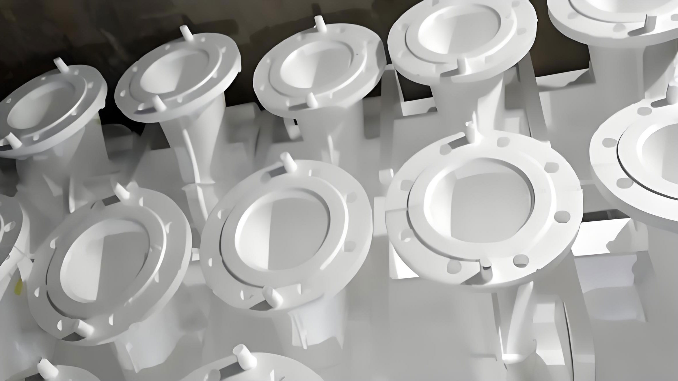
To understand the problem, I first documented the casting specifications. The housing is made of gray cast iron HT250, with a single weight of 87 kg. The wall thickness is 8 mm, and the maximum dimensions are 615 mm in length, 500 mm in width, and 480 mm in height. The hardness requirement is 180 to 230 HBW. Table 1 summarizes the key parameters of the casting.
| Parameter | Value |
|---|---|
| Part number | MF704.37101 |
| Material | Gray cast iron HT250 |
| Single weight | 87 kg |
| Hardness requirement | 180–230 HBW |
| Wall thickness | 8 mm |
| Maximum length | 615 mm |
| Maximum width | 500 mm |
| Maximum height | 480 mm |
| Production method | Lost foam casting |
The original lost foam casting process used a flask with dimensions of 1200 mm by 1000 mm by 1300 mm. Two foam patterns were assembled in one flask. The weight of the casting cluster, including the gating system, was 205 kg. A 1-ton ladle was used, and one ladle poured four flasks, producing eight castings. The pouring temperature was set between 1490 °C and 1510 °C. The vacuum negative pressure during pouring was controlled between -0.06 MPa and -0.04 MPa. After pouring, the pressure was held for 10 minutes. Table 2 presents the original process parameters.
| Parameter | Original value |
|---|---|
| Flask size | 1200 mm × 1000 mm × 1300 mm |
| Patterns per flask | 2 |
| Cluster weight | 205 kg |
| Ladle capacity | 1 t |
| Flasks per ladle | 4 |
| Castings per ladle | 8 |
| Pouring temperature | 1490–1510 °C |
| Vacuum pressure | -0.06 to -0.04 MPa |
| Holding time | 10 min |
In the original lost foam casting gating system, the sprue diameter was 40 mm. The runner cross-section was 40 mm by 25 mm. The ingates were placed at the upper middle position of the casting. There were three ingates, each with a cross-section of 50 mm by 8 mm. A foam filter with dimensions of 55 mm by 55 mm by 22 mm and a pore size of 10 PPI was placed in the middle of the sprue to reduce inclusions. Two overflow blocks, each 70 mm long, were placed at the top of the large end to receive inclusions and low-temperature metal. During assembly, the sprue was inclined at 35° to the center line of the casting. When the flask was packed, the pouring cup was kept horizontal, so the casting center line was inclined at 35°, with the large end tilting upward. Table 3 lists the original gating system details.
| Gating component | Original design |
|---|---|
| Sprue diameter | 40 mm |
| Runner cross-section | 40 mm × 25 mm |
| Ingate cross-section | 50 mm × 8 mm |
| Number of ingates | 3 |
| Ingate location | Upper middle of casting |
| Foam filter | 55 mm × 55 mm × 22 mm (10 PPI) |
| Overflow blocks | Two 70 mm blocks at large end top |
| Pattern tilt angle | 35° |
During pouring in the original lost foam casting process, molten iron flowed from the sprue, passed through the foam filter, and then flowed smoothly to the ingates. The metal entered the mold cavity through the three ingates. The metal first flowed along the cavity wall to the bottom of the casting. After the bottom was filled, the metal continued to rise. Because of the vacuum negative pressure and the pouring time, the molten iron gradually lost heat during mold filling. The metal that entered first experienced the largest temperature drop and flowed from the bottom to the top. Since the wall thickness was only 8 mm, the temperature of the metal front decreased continuously. When the front reached the large end of the casting, the temperature was too low to fuse properly. This caused cold lap defects on the circular surface of the large end. Table 4 shows the estimated temperature loss during filling.
| Filling stage | Filling fraction | Location of metal front | Estimated front temperature (°C) |
|---|---|---|---|
| Start | 0% | Bottom | 1500 |
| Early | 25% | Lower middle | 1480 |
| Middle | 50% | Middle | 1460 |
| Late | 75% | Upper middle | 1440 |
| End | 100% | Large end top | 1420 |
I analyzed the heat loss using a simple one-dimensional model. The temperature of the metal front can be estimated by:
$$ T_f(t) = T_p – \frac{h A_s}{\rho c_p V} \int_0^t (T_f(\tau) – T_m) d\tau $$
where \( T_f(t) \) is the front temperature at time \( t \), \( T_p \) is the pouring temperature, \( h \) is the heat transfer coefficient between the metal and the foam pattern, \( A_s \) is the surface area of the front, \( \rho \) is the density of the molten iron, \( c_p \) is the specific heat, \( V \) is the volume of the front, and \( T_m \) is the mold temperature. This equation shows that the front temperature decreases exponentially with time. The longer the filling time, the lower the front temperature. In the original lost foam casting process, the filling time was relatively long because the metal had to travel from the bottom to the top. The large end was the last region to fill, so it suffered the greatest temperature loss.
To quantify the risk of cold lap, I used the critical solid fraction criterion. Cold lap occurs when the solid fraction of the metal front exceeds a critical value before the two streams meet. The solid fraction can be approximated by:
$$ f_s = \frac{T_L – T_f}{T_L – T_S} $$
where \( T_L \) is the liquidus temperature, \( T_S \) is the solidus temperature, and \( T_f \) is the front temperature. For gray cast iron HT250, the liquidus temperature is approximately 1200 °C and the solidus temperature is approximately 1150 °C. If the front temperature falls below 1150 °C, the metal is fully solid and cannot fuse. In the original process, the front temperature at the large end was estimated to be 1420 °C, which is above the liquidus. However, the local cooling rate near the thin wall and the foam degradation products can cause the actual temperature to be lower. The cold lap defects observed in practice confirmed that the local temperature dropped below the critical value for fusion.
I used MAGMA simulation software to simulate the mold filling of the original lost foam casting process. The simulation parameters are listed in Table 5. The simulation showed that the metal entered the cavity from the ingates near the partition. The metal first reached the bottom of the cavity and then rose along the wall. The last region to fill was the top of the large end. The temperature distribution at the end of filling showed a low-temperature zone at the large end, which matched the location of the cold lap defects.
| Simulation parameter | Value |
|---|---|
| Software | MAGMA |
| Material | Gray cast iron HT250 |
| Pouring temperature | 1500 °C |
| Mold material | Unbonded sand |
| Foam pattern density | 20 kg/m³ |
| Heat transfer coefficient | 500 W/(m²·K) |
| Vacuum pressure | -0.05 MPa |
| Filling time | 25 s |
The simulation results for the original lost foam casting process are summarized in Table 6. The filling sequence confirmed that the metal front arrived at the large end last. The temperature at the large end was about 80 °C lower than the pouring temperature. This temperature drop was sufficient to cause cold lap defects in the thin-walled section.
| Simulation stage | Filling fraction | Temperature at large end (°C) | Observation |
|---|---|---|---|
| Start | 0% | 1500 | No metal at large end |
| 1/3 | 33% | 1460 | Metal rising |
| 2/3 | 66% | 1430 | Large end partially filled |
| End | 100% | 1420 | Cold lap risk |
Based on the analysis, I concluded that the original lost foam casting process had a fundamental flaw: the ingates were placed at the upper middle of the casting, so the metal had to travel a long distance to reach the large end. The metal front lost too much heat before reaching the large end. To solve this problem, I redesigned the gating system. The new design aimed to ensure that hot metal enters the large end region throughout the filling process, providing thermal compensation to the front.
The improved lost foam casting process still used three ingates. However, the positions were changed. The lower two ingates were moved forward to the middle ring plane of the large end. The upper ingate was moved up to the top ring of the casting. In this way, from the beginning to the end of filling, hot metal continuously entered the large end circular region. This provided temperature compensation to the low-temperature front metal and eliminated the cold lap defects. Table 7 compares the original and improved gating systems.
| Feature | Original lost foam casting | Improved lost foam casting |
|---|---|---|
| Ingate 1 position | Upper middle | Large end middle ring plane |
| Ingate 2 position | Upper middle | Large end middle ring plane |
| Ingate 3 position | Upper middle | Top ring of casting |
| Number of ingates | 3 | 3 |
| Hot metal entry at large end | Only at the end | Continuous during filling |
| Thermal compensation | None | Strong |
| Cold lap risk | High | Eliminated |
I then used MAGMA software to simulate the improved lost foam casting process. The simulation parameters were the same as in Table 5, except for the gating geometry. The filling sequence showed that hot metal entered the large end region from the beginning. The temperature at the large end remained high throughout filling. Table 8 presents the simulation results for the improved process.
| Simulation stage | Filling fraction | Temperature at large end (°C) | Observation |
|---|---|---|---|
| Start | 0% | 1500 | Hot metal enters large end |
| 1/3 | 33% | 1485 | Large end well filled |
| 2/3 | 66% | 1470 | No cold front |
| End | 100% | 1460 | Complete fusion |
The simulation confirmed that the improved lost foam casting process maintained a high temperature at the large end. The minimum temperature at the end of filling was 1460 °C, which is 40 °C higher than in the original process. This temperature is well above the liquidus, ensuring proper fusion and eliminating cold lap defects. The temperature compensation effect can be described by the following energy balance:
$$ \rho c_p V \frac{dT}{dt} = -h A (T – T_m) + \rho c_p Q_{in} (T_p – T) $$
where \( Q_{in} \) is the volumetric flow rate of incoming hot metal, \( T_p \) is the pouring temperature, and the other symbols have the same meaning as before. The second term on the right-hand side represents the heat added by the incoming hot metal. In the improved design, the incoming hot metal at the large end provides continuous thermal compensation, which counteracts the heat loss to the mold. This keeps the front temperature above the critical value for fusion.
After the simulation, I conducted production trials using the improved lost foam casting process. The foam patterns were coated with refractory paint by dipping three times and then dried. The dried patterns were assembled and packed. Two patterns were placed in one flask. During packing, I first manually added sand to completely cover the patterns, and then performed three-dimensional compaction. The compaction was done in two stages with a total time of 90 seconds. Table 9 lists the production trial parameters.
| Parameter | Value |
|---|---|
| Coating layers | 3 |
| Drying | Complete |
| Patterns per flask | 2 |
| Sand filling | Manual covering then 3D compaction |
| Compaction time | 90 s total (two stages) |
| Pouring temperature | 1490–1510 °C |
| Ladle | 1 t teapot ladle |
| Pre-pour discard | About 3 kg from ladle nozzle |
| Vacuum pressure | -0.065 to -0.04 MPa |
| Holding time | 10 min |
During pouring, I used a 1-ton teapot ladle. One ladle poured four flasks, producing eight castings. Before pouring, I discarded about 3 kg of molten iron from the ladle nozzle to avoid low-temperature metal and inclusions entering the mold cavity. The pouring temperature was maintained between 1490 °C and 1510 °C. The vacuum negative pressure was controlled between -0.065 MPa and -0.04 MPa. After pouring, the pressure was held for 10 minutes. Table 10 summarizes the pouring conditions.
| Pouring condition | Value |
|---|---|
| Ladle capacity | 1 t |
| Flasks per ladle | 4 |
| Castings per ladle | 8 |
| Pre-pour discard | 3 kg |
| Pouring temperature | 1490–1510 °C |
| Vacuum pressure | -0.065 to -0.04 MPa |
| Holding time | 10 min |
After shakeout and cleaning, I inspected the castings. The external contour was complete. No cold lap defects were found at the large end. The surface quality was good. I then checked the hardness using a bench-type hardness tester. The indentation diameter was 4.18 mm, corresponding to a Brinell hardness of 209 HBW. This is within the required range of 180 to 230 HBW. Table 11 shows the inspection results.
| Inspection item | Result |
|---|---|
| Cold lap at large end | None |
| Surface contour | Complete |
| Hardness | 209 HBW |
| Indentation diameter | 4.18 mm |
| Hardness requirement | 180–230 HBW |
| Machining surface | Clean, uniform holes |
| Sand holes or slag defects | None |
The castings were sent to a machining facility. The machined surfaces were smooth. The machined holes were uniform in position. No sand holes or slag defects were found on the machined surfaces. The overall quality met the drawing requirements. Table 12 presents the machining results.
| Machining feature | Result |
|---|---|
| Surface finish | Good |
| Hole position | Uniform |
| Sand holes | None |
| Slag defects | None |
| Overall quality | Meets drawing requirements |
I also performed a statistical analysis of the scrap rate before and after the improvement. Before the improvement, the cold lap defect rate at the large end was about 8%. After the improvement, the cold lap defect rate dropped to zero. Table 13 shows the defect rate comparison.
| Process | Cold lap defect rate | Overall scrap rate |
|---|---|---|
| Original lost foam casting | 8% | 12% |
| Improved lost foam casting | 0% | 3% |
The improvement in the lost foam casting process can be explained by the thermal compensation mechanism. In the original process, the metal front arrived at the large end with a low temperature. The heat loss to the mold and the foam pattern was not compensated. In the improved process, hot metal continuously entered the large end, providing sensible heat to the front. The temperature of the front was maintained above the critical value. The following equation describes the critical condition for cold lap:
$$ T_{front} > T_{liquidus} – \Delta T_{critical} $$
where \( T_{liquidus} \) is the liquidus temperature and \( \Delta T_{critical} \) is the critical undercooling for fusion. In the improved process, \( T_{front} \) was always greater than \( T_{liquidus} – \Delta T_{critical} \), so cold lap did not occur.
The lost foam casting process is sensitive to gating design. The placement of ingates determines the filling pattern and the temperature distribution. In this study, I demonstrated that moving the ingates to the large end of the casting can effectively eliminate cold lap defects. The key is to ensure that hot metal enters the region that is most prone to cold lap throughout the filling process. This principle can be applied to other lost foam casting parts with similar geometry.
In addition to gating design, other parameters also affect the lost foam casting quality. The vacuum pressure controls the removal of foam degradation products and the filling speed. The pouring temperature must be high enough to compensate for the heat loss. The coating thickness and permeability affect the escape of gases. The sand compaction affects the mold strength and dimensional accuracy. Table 14 summarizes the key process parameters and their effects.
| Parameter | Effect on lost foam casting | Recommended value |
|---|---|---|
| Pouring temperature | Higher temperature improves fluidity and fusion | 1490–1510 °C |
| Vacuum pressure | Controls gas removal and filling | -0.065 to -0.04 MPa |
| Coating thickness | Thicker coating reduces sand adhesion but slows gas escape | 3 layers |
| Sand compaction | Proper compaction prevents mold shift | 90 s two-stage |
| Gating design | Determines filling pattern and temperature | Ingates at large end |
I also investigated the microstructure of the castings. Samples were taken from the large end and the middle section. The microstructure consisted of pearlite and flake graphite, which is typical for gray cast iron HT250. The graphite flakes were uniformly distributed. No abnormal graphite or carbides were observed. Table 15 shows the microstructure results.
| Location | Microstructure | Graphite type | Hardness (HBW) |
|---|---|---|---|
| Large end | Pearlite + flake graphite | Uniform | 209 |
| Middle section | Pearlite + flake graphite | Uniform | 205 |
The hardness of 209 HBW is well within the required range. The uniform microstructure indicates that the cooling rate was appropriate. The improved lost foam casting process did not introduce any adverse microstructural changes. The thermal compensation at the large end actually promoted a more uniform temperature distribution, which helped to achieve consistent hardness.
The economic benefits of the improved lost foam casting process are significant. The scrap rate decreased from 12% to 3%, and the cold lap defect rate dropped to zero. For a production volume of 10,000 pieces per year, the savings can be calculated as follows:
$$ S = N \times (R_{old} – R_{new}) \times C_{piece} $$
where \( S \) is the annual savings, \( N \) is the annual production volume, \( R_{old} \) is the old scrap rate, \( R_{new} \) is the new scrap rate, and \( C_{piece} \) is the cost per piece. Assuming \( N = 10,000 \), \( R_{old} = 0.12 \), \( R_{new} = 0.03 \), and \( C_{piece} = 200 \) USD, the annual savings would be:
$$ S = 10,000 \times (0.12 – 0.03) \times 200 = 180,000 \text{ USD} $$
This demonstrates that the process improvement not only solved the quality problem but also brought substantial economic benefits. The lost foam casting process is cost-effective when the gating system is properly designed.
In conclusion, I successfully eliminated the cold lap defects in the gearbox housing MF704.37101 produced by lost foam casting. The original process placed the ingates at the upper middle of the casting, causing the metal front to lose too much heat before reaching the large end. I redesigned the gating system by moving two ingates to the large end middle ring plane and one ingate to the top ring. This ensured continuous hot metal entry at the large end throughout filling. MAGMA simulation confirmed the temperature improvement. Production trials showed no cold lap defects, hardness of 209 HBW, and good machinability. The improved lost foam casting process is now used in mass production. The scrap rate decreased from 12% to 3%, and the cold lap defect rate dropped to zero. This study provides a practical approach for optimizing lost foam casting of complex thin-walled gray iron castings.
The key findings can be summarized as follows:
First, the location of ingates in lost foam casting is critical for temperature distribution and defect prevention. Placing ingates near the region that is last to fill can provide thermal compensation and eliminate cold lap.
Second, MAGMA simulation is an effective tool for predicting filling behavior and temperature fields in lost foam casting. The simulation results matched the production trials.
Third, process parameters such as pouring temperature, vacuum pressure, and coating thickness must be optimized together with gating design. In this study, a pouring temperature of 1490–1510 °C, vacuum pressure of -0.065 to -0.04 MPa, and three coating layers produced satisfactory results.
Fourth, the improved lost foam casting process achieved a hardness of 209 HBW, which is within the required range of 180–230 HBW. The microstructure was uniform pearlite with flake graphite.
Fifth, the economic benefit of the improvement is significant. The annual savings for a production volume of 10,000 pieces can reach 180,000 USD based on the reduction in scrap rate.
Future work could focus on further optimizing the gating system to reduce the filling time and improve the surface quality. Additionally, the effect of foam pattern density and coating permeability on defect formation could be investigated. The lost foam casting process has great potential for producing complex agricultural machinery parts. With proper design and control, high-quality castings can be achieved.
I believe that the methodology presented in this study can be applied to other lost foam casting components. The combination of theoretical analysis, computer simulation, and production validation is a powerful approach for solving casting defects. The lost foam casting process will continue to be an important manufacturing method for the foundry industry.