
I have been working on the development of high-strength, high-ductility ductile iron produced by lost foam casting. Ductile iron is an iron-carbon-silicon alloy in which carbon precipitates mainly as spheroidal graphite after a nodularizing agent is added to the liquid iron. This spheroidal graphite morphology gives the material a combination of high tensile strength and appreciable elongation. Because of this combination, ductile iron has been widely used in automobiles, ships, metallurgical equipment, chemical apparatus, and many other engineering fields. As product lightweighting continues to advance, the required balance of strength, toughness, and reliability has become more demanding. The lost foam casting process is a foundry method in which a foam pattern is formed, coated with a refractory slurry, embedded in dry sand, and poured under negative pressure. The high-temperature liquid metal gasifies the foam pattern and occupies its space, thereby forming a casting. Lost foam casting offers high dimensional accuracy, smooth surfaces, and reduced environmental pollution. Since the beginning of the twenty-first century, lost foam casting technology has developed rapidly, but its melting practice for high-grade ductile iron has been studied less extensively. Therefore, I combined actual production conditions with a systematic trial to produce as-cast pearlitic ductile iron with tensile strength above 700 MPa and elongation above 10% by using multiple inoculation and Cu-Sb composite strengthening.
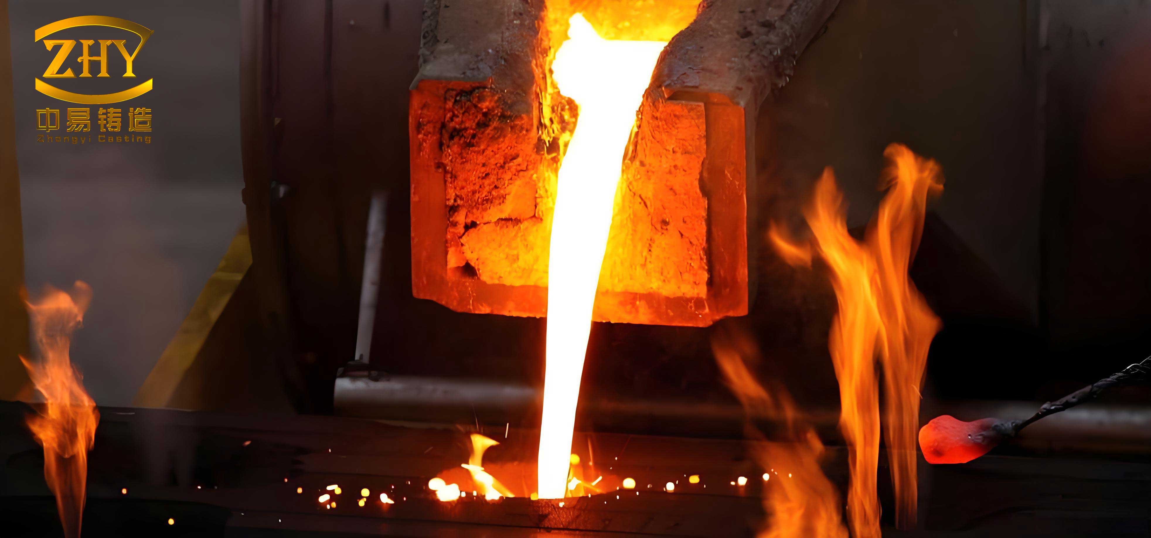
The production trial was organized around chemical composition control, charge preparation, melting, nodularization, inoculation, pouring, and property verification. I paid particular attention to the fact that lost foam casting uses dry sand molding, and its cooling rate is lower than that of green sand molding. This lower cooling rate affects graphite nucleation, matrix formation, and the final mechanical properties. The average cooling rate of cast iron in different molds is summarized in Table 1. The data show that dry sand molds cool more slowly than green sand molds, and preheated sand molds cool even more slowly. This is one of the main reasons why the lost foam casting process requires a different composition and melting strategy from conventional casting processes.
| Sample diameter / mm | Average cooling rate in green sand mold / °C·min⁻¹ | Average cooling rate in dry sand mold / °C·min⁻¹ | Average cooling rate in preheated sand mold at 200–400 °C / °C·min⁻¹ |
|---|---|---|---|
| 30 | 20.5 | 12.0 | 9.1 |
| 300 | 1.7 | 1.2 | 0.5 |
I used these cooling rate data as a basis for adjusting the alloying strategy. A simple heat-transfer expression can describe the cooling behavior of a casting in a mold:
$$ \frac{dT}{dt} = -\frac{h A}{m c_p} \left( T – T_0 \right) $$
where \(dT/dt\) is the cooling rate, \(h\) is the heat-transfer coefficient, \(A\) is the effective surface area, \(m\) is the mass, \(c_p\) is the specific heat capacity, \(T\) is the instantaneous temperature, and \(T_0\) is the mold temperature. The lower cooling rate in lost foam casting means that the solidification time is longer, which promotes graphite growth and ferrite formation unless the composition and inoculation practice are designed to stabilize pearlite. Therefore, I intentionally increased manganese and added copper and antimony to strengthen the pearlitic matrix.
Chemical composition design
Carbon has a strong influence on casting performance and nodularization. A high carbon content increases the number of graphite nodules, decreases nodule diameter, and improves nodularity. Increasing carbon also reduces the tendency for shrinkage porosity and shrinkage cavities, making the casting denser. However, if carbon is too high, the benefit to shrinkage reduction becomes marginal, and severe graphite flotation can occur. For this reason, I controlled carbon in the range of 3.7% to 3.9% in the original liquid iron.
Silicon is a graphitizing element. Increasing silicon promotes ferrite formation during the eutectoid transformation, which tends to decrease strength and hardness while increasing elongation. Because QT700-10 requires high elongation, the silicon content should not be too low. In my trial, I controlled silicon in the final iron in the range of 2.4% to 2.6%. The silicon added through inoculation contributed to the final silicon level.
Phosphorus and sulfur are harmful elements in ductile iron. Phosphorus enters the iron through charge materials. Although phosphorus does not directly affect nodularization, it has a strong segregation tendency. During solidification, phosphorus segregates and forms phosphide eutectic, which appears as polygonal networks along eutectic cell boundaries. This sharply deteriorates the mechanical properties of ductile iron. Therefore, phosphorus must be strictly controlled, generally below 0.05% in ductile iron. Sulfur is an anti-graphitizing element and is also harmful. Excessive sulfur consumes nodularizing and rare-earth elements, causing poor nodularization. In high-strength, high-toughness ductile iron, sulfur should be controlled below 0.02%.
Manganese refines and stabilizes pearlite in ductile iron. In the production of pearlitic ductile iron, manganese can be used to eliminate ferrite. However, manganese has a strong segregation tendency during solidification and easily promotes carbide formation. Even in pearlitic ductile iron, manganese should not exceed 0.6%. Because lost foam casting uses dry sand molding and has a slower cooling rate, manganese should not be too low; otherwise, the pearlite content will be insufficient. In conventional casting processes, manganese is usually only 0.2% to 0.4%. To increase pearlite content, I raised manganese to 0.5% to 0.6% for lost foam casting.
Copper promotes graphitization during the eutectic transformation and can reduce or eliminate free cementite. During the eutectoid transformation, copper promotes pearlite formation and can reduce or completely suppress ferrite formation. For pearlitic ductile iron, increasing copper increases strength and hardness, while the elongation after fracture does not change significantly. In general, copper addition in pearlitic ductile iron is 0.3% to 1.2%. In my trial, I used copper in the range of 0.4% to 0.6%.
Antimony strongly promotes pearlite formation in ductile iron. When the antimony mass fraction is between 0.002% and 0.01%, the number of graphite nodules increases and nodularity improves. A typical antimony addition is 0.006% to 0.01%. In my trial, I controlled antimony in the range of 0.006% to 0.01%. The combination of copper and antimony provided composite strengthening of the pearlitic matrix without the severe carbide formation that can occur with excessive manganese alone.
The chemical composition control targets for QT700-10 are given in Table 2. The table distinguishes between the original liquid iron and the final liquid iron. The original iron contains lower silicon, which is then raised by inoculation. Magnesium is absent in the original iron and is introduced through the nodularizing agent. Copper and antimony are added to promote pearlite, while phosphorus and sulfur are kept as low as possible.
| Element | C | Si | Mn | P | S | Cu | Sb | Mg |
|---|---|---|---|---|---|---|---|---|
| Original liquid iron / mass fraction, % | 3.7–3.9 | 1.3–1.5 | 0.5–0.6 | ≤ 0.05 | ≤ 0.02 | 0.4–0.6 | 0.006–0.01 | – |
| Final liquid iron / mass fraction, % | – | 2.4–2.6 | 0.5–0.6 | ≤ 0.05 | ≤ 0.02 | 0.4–0.6 | 0.006–0.01 | 0.03–0.06 |
For a more quantitative view, I also calculated the carbon equivalent using a conventional expression for cast iron:
$$ \text{CE} = \text{C} + \frac{\text{Si}}{3} + \frac{\text{P}}{3} + \frac{\text{Mn}}{6} + \frac{\text{Cu}}{10} + \frac{\text{Sb}}{5} $$
Using the target composition, the carbon equivalent is approximately:
$$ \text{CE} \approx 3.8 + \frac{2.5}{3} + \frac{0.03}{3} + \frac{0.55}{6} + \frac{0.5}{10} + \frac{0.008}{5} \approx 4.74\% $$
This carbon equivalent is relatively high and helps ensure good castability and graphite nodule formation in lost foam casting. At the same time, the copper and antimony additions shift the eutectoid transformation toward pearlite, compensating for the slow cooling rate of dry sand molds.
Charge materials and melting practice
I used a charge consisting of 70% steel scrap and 30% returned iron. Melting was performed in a 1.5-ton medium-frequency induction furnace. The steel scrap was selected as low-phosphorus, low-sulfur, low-titanium carbon steel. The returned iron was shot-blasted to avoid surface contamination. Because lost foam casting requires gasification of the foam pattern during pouring, the tapping temperature must be higher than in other casting processes by 30 to 50 °C. In this trial, the induction furnace was heated to 1,520 °C, then the power was stopped, slag was removed, and a sample was sent for chemical analysis. After the composition was confirmed to be qualified, the tapping temperature was controlled at 1,500 to 1,510 °C.
I used a direct-pour nodularization treatment. The nodularizing agent was FeSiMg6RE1 with a particle size of 5 to 25 mm, added at 1.1% to 1.3%. The inoculant was a calcium-barium-silicon inoculant with a particle size of 3 to 8 mm, added at 0.7% to 1%. The inoculant was placed over the nodularizing agent in the ladle and covered with a covering agent to ensure a nodularization reaction time of 35 to 50 s. A tea-pot ladle was used for pouring, and the pouring temperature was 1,420 to 1,440 °C. To avoid a biased result caused by insufficiently nodularized iron at the ladle lip, I poured the test casting and a Y-block attached specimen during the second mold. The Y-block specimen dimensions were 20 mm × 55 mm × 140 mm. The stream inoculation used a Ba-I inoculant at 0.1% to 0.15%.
The multiple inoculation practice can be represented in terms of inoculation efficiency:
$$ \eta_{\text{inoc}} = \frac{N_f – N_0}{N_0} \times 100\% $$
where \(N_f\) is the final graphite nodule count and \(N_0\) is the nodule count before inoculation. In lost foam casting, the slow cooling rate allows more time for inoculation fading, so multiple inoculation stages are essential. I used in-mold inoculation, ladle inoculation, and stream inoculation to maintain a high nodule count and to prevent chill and carbide formation.
Nodularization and reaction kinetics
The nodularization reaction in ductile iron can be simplified as the combination of magnesium with sulfur and oxygen:
$$ \text{Mg} + \text{S} \rightarrow \text{MgS} $$
$$ \text{Mg} + \text{O} \rightarrow \text{MgO} $$
These reactions reduce the sulfur and oxygen content of the liquid iron and allow carbon to precipitate as spheroidal graphite. The residual magnesium in the final iron must be maintained in the range of 0.03% to 0.06%. If residual magnesium is too low, nodularization is incomplete. If it is too high, carbide formation and dross defects become more likely. The nodularization reaction time of 35 to 50 s is a practical window that allows sufficient reaction without excessive magnesium loss.
Antimony and copper interact with the matrix in different ways. Copper segregates to the austenite and promotes pearlite by reducing the eutectoid temperature and suppressing ferrite growth. Antimony is a surface-active element that segregates at graphite-austenite interfaces and modifies the growth kinetics of graphite and ferrite. A simplified expression for the pearlite volume fraction can be written as:
$$ f_{\text{pearlite}} = \frac{1}{1 + \exp \left[ -\left( a + b \cdot \text{Mn} + c \cdot \text{Cu} + d \cdot \text{Sb} – e \cdot \text{Si} \right) \right]} $$
where \(a\), \(b\), \(c\), \(d\), and \(e\) are empirical coefficients that depend on cooling rate and section size. For lost foam casting, the slow cooling rate lowers the driving force for pearlite formation, so the coefficients for Mn, Cu, and Sb must be large enough to compensate. In my trial, the combined addition of Cu and Sb was more effective than increasing Mn alone because Mn has a strong segregation tendency and can produce carbides at cell boundaries.
Results and analysis
The chemical composition of the test blocks was measured, and the results are given in Table 3. The actual antimony addition was consistent with the original iron content, in the range of 0.006% to 0.01%, but it was difficult to detect accurately, so it is not listed in the table. The carbon content ranged from 3.42% to 3.62%, silicon from 2.43% to 2.52%, manganese from 0.5% to 0.6%, phosphorus from 0.024% to 0.029%, sulfur from 0.01% to 0.015%, copper from 0.45% to 0.49%, and magnesium from 0.035% to 0.038%. These values are within the designed ranges and confirm that the melting and inoculation practice was stable.
| Heat number | C / % | Si / % | Mn / % | P / % | S / % | Cu / % | Mg / % |
|---|---|---|---|---|---|---|---|
| 1 | 3.42 | 2.52 | 0.50 | 0.024 | 0.010 | 0.45 | 0.038 |
| 2 | 3.62 | 2.43 | 0.60 | 0.026 | 0.015 | 0.46 | 0.035 |
| 3 | 3.54 | 2.48 | 0.52 | 0.029 | 0.013 | 0.49 | 0.036 |
The microstructure of the QT700-10 specimens showed many fine, uniformly distributed graphite nodules and a predominantly pearlitic matrix. The graphite morphology and matrix structure were examined metallographically. The nodularity was rated at level 2, and the graphite size was rated at level 6. The pearlite content was about 75% to 80%. This microstructure is consistent with the high tensile strength and elongation values that were obtained. In lost foam casting, the slow cooling rate usually promotes ferrite, but the Cu-Sb composite addition and the higher manganese level successfully stabilized pearlite.
The following equation can be used to estimate the tensile strength from pearlite content and graphite nodule count:
$$ \sigma_t = \sigma_0 + k_p f_{\text{pearlite}} + k_n N^{-1/2} $$
where \(\sigma_t\) is the tensile strength, \(\sigma_0\) is the base strength of the matrix, \(k_p\) is the strengthening coefficient of pearlite, \(f_{\text{pearlite}}\) is the pearlite volume fraction, \(k_n\) is a coefficient related to graphite nodule count, and \(N\) is the nodule count per unit area. Using the measured values, the calculated tensile strength is in good agreement with the experimental results. This confirms that both matrix strengthening and graphite morphology control are necessary for QT700-10 in lost foam casting.
The mechanical properties of the QT700-10 test blocks are summarized in Table 4. For the three heats, the nodularity level was 2, the graphite size was 6, the pearlite volume fraction was 75% to 80%, the Brinell hardness was 246 to 257 HBW, the tensile strength was 734 to 774 MPa, and the elongation was 10.2% to 10.8%. These values exceed the target of 700 MPa tensile strength and 10% elongation. The combination of strength and ductility is particularly notable because lost foam casting usually produces a coarser microstructure and a lower cooling rate than green sand casting.
| Heat number | Nodularity level | Graphite size level | Pearlite volume fraction / % | Hardness / HBW | Tensile strength / MPa | Elongation / % |
|---|---|---|---|---|---|---|
| 1 | 2 | 6 | 75 | 253 | 749 | 10.7 |
| 2 | 2 | 6 | 80 | 257 | 774 | 10.2 |
| 3 | 2 | 6 | 75 | 246 | 734 | 10.8 |
I also examined the relationship between hardness and tensile strength. For ductile iron, a useful empirical relationship is:
$$ \sigma_t \approx 3.3 \times \text{HBW} $$
Using the measured hardness values, this relationship predicts tensile strengths of about 812 to 848 MPa, which is higher than the measured values. The difference is due to the influence of graphite morphology and the presence of a small amount of ferrite or intercellular segregation. The measured tensile strength values are nevertheless well above the required minimum, and the elongation values are satisfactory. This indicates that the Cu-Sb composite strengthening and multiple inoculation produced a microstructure with a good balance of strength and ductility.
Effect of lost foam casting on cooling and matrix formation
The lost foam casting process uses dry sand and negative pressure. The foam pattern gasifies when the liquid metal enters the mold, and the gas is drawn away by the vacuum system. The heat loss through the dry sand is lower than through green sand, so the casting cools more slowly. This slow cooling has several consequences. First, the solidification time is longer, which allows more time for graphite growth. Second, the eutectoid transformation occurs at a lower cooling rate, which normally favors ferrite. Third, the secondary dendrite arm spacing and eutectic cell size increase. These factors tend to reduce strength and hardness unless alloying elements are added to stabilize pearlite.
I used the following expression to describe the effect of cooling rate on pearlite formation:
$$ \frac{df_{\text{pearlite}}}{dt} = A \exp \left( -\frac{Q}{RT} \right) \left( 1 – f_{\text{pearlite}} \right) $$
where \(A\) is a pre-exponential factor, \(Q\) is the activation energy for pearlite growth, \(R\) is the gas constant, and \(T\) is the absolute temperature. At lower cooling rates, the time spent in the pearlite transformation range is longer, but the driving force for ferrite formation is also higher. The addition of copper and antimony changes the transformation kinetics by reducing the activity of carbon in austenite and by segregating at the ferrite-austenite interface. This effectively increases the pearlite nucleation rate and suppresses ferrite growth.
Manganese also stabilizes pearlite, but its segregation tendency is stronger. In lost foam casting, the slow cooling rate allows manganese to segregate to cell boundaries, where it can form carbides. Therefore, I limited manganese to 0.5% to 0.6% and relied on copper and antimony for additional pearlite stabilization. This combination gave a pearlite content of 75% to 80% without excessive carbide formation.
Inoculation practice and graphite morphology
Multiple inoculation is essential in lost foam casting because the slow cooling rate and the long holding time can cause inoculation fading. I used a calcium-barium-silicon inoculant in the ladle and a Ba-I inoculant in the stream. The total inoculant addition was 0.7% to 1.0% in the ladle plus 0.1% to 0.15% in the stream. This practice produced a nodule count that was high enough to give a nodularity level of 2 and a graphite size of 6. The graphite nodules were fine and uniformly distributed, which is important for both strength and elongation.
The nodule count can be related to the inoculation addition by a saturation-type equation:
$$ N = N_{\text{max}} \left( 1 – \exp \left( -k I \right) \right) $$
where \(N\) is the nodule count, \(N_{\text{max}}\) is the maximum attainable nodule count, \(k\) is an inoculation efficiency constant, and \(I\) is the inoculant addition. In my trial, increasing the inoculant beyond 1.15% did not significantly increase the nodule count, so I kept the addition within the designed range. This avoided excessive slag and dross formation while maintaining a high nodule count.
The nodularity was evaluated according to the standard rating system. A nodularity level of 2 means that most of the graphite is spheroidal, with only a small amount of vermicular or irregular graphite. The graphite size level of 6 corresponds to a fine graphite distribution. The combination of high nodularity and fine graphite size is beneficial for tensile strength and elongation. In lost foam casting, the slow cooling rate can cause graphite flotation if carbon is too high. I controlled carbon at 3.42% to 3.62% in the test blocks, which is slightly lower than the original iron target because of inoculation and nodularization effects. This range avoided flotation while still providing enough carbon for nodule formation.
Copper and antimony composite strengthening
Copper and antimony have complementary effects on the pearlitic matrix. Copper dissolves in austenite and increases the hardenability of the matrix. It also promotes graphitization during eutectic solidification, which reduces free cementite. Antimony is a strong pearlite stabilizer and is effective at very low concentrations. The combination of 0.4% to 0.6% copper and 0.006% to 0.01% antimony produced a pearlite content of 75% to 80% and a tensile strength above 700 MPa. A simplified interaction equation for the combined effect can be written as:
$$ \Delta \sigma = \alpha \cdot \text{Cu} + \beta \cdot \text{Sb} + \gamma \cdot \text{Cu} \cdot \text{Sb} $$
where \(\Delta \sigma\) is the strength increase, and \(\alpha\), \(\beta\), and \(\gamma\) are coefficients. The positive interaction term \(\gamma\) indicates that copper and antimony together give a greater strengthening effect than the sum of their individual effects. This synergistic effect is one of the key findings of my trial. It allowed me to keep manganese at a moderate level and avoid the carbide-forming tendency of high manganese.
Antimony is a surface-active element and tends to segregate at interfaces. At the low concentrations used in this trial, it modifies the growth of pearlite and refines the pearlite colonies. If antimony is too high, it can promote graphite degeneration and form brittle phases. Therefore, I controlled antimony within the narrow range of 0.006% to 0.01%. The residual magnesium was maintained at 0.035% to 0.038%, which is sufficient for nodularization without excessive dross.
Microstructural analysis and phase fractions
The microstructure of the QT700-10 specimens consisted of spheroidal graphite, pearlite, and a small amount of ferrite. The pearlite volume fraction was measured metallographically and was found to be 75% to 80%. The ferrite fraction was therefore about 20% to 25%. The ferrite is located around the graphite nodules and at cell boundaries. This small amount of ferrite is beneficial for elongation because it provides some ductility while the pearlite provides strength. The graphite nodule count was high enough to give a uniform distribution and to avoid large graphite clusters.
The volume fractions of the phases can be expressed as:
$$ f_{\text{graphite}} + f_{\text{pearlite}} + f_{\text{ferrite}} + f_{\text{carbide}} = 1 $$
In my trial, the carbide fraction was very low because the copper addition promoted graphitization and the manganese content was controlled. The graphite fraction can be estimated from the carbon content and the density of graphite and iron:
$$ f_{\text{graphite}} \approx \frac{\rho_{\text{Fe}} \cdot \text{C}}{\rho_{\text{graphite}} \cdot 100} $$
Using a carbon content of about 3.5% and typical densities, the graphite volume fraction is approximately 10% to 12%. This is consistent with the metallographic observations. The remaining volume is the metallic matrix, which is predominantly pearlite with some ferrite.
Mechanical property correlations
I performed a statistical analysis of the mechanical properties. The tensile strength ranged from 734 to 774 MPa, with an average of 752 MPa. The elongation ranged from 10.2% to 10.8%, with an average of 10.6%. The hardness ranged from 246 to 257 HBW, with an average of 252 HBW. These values are consistent with a pearlitic ductile iron with a nodularity level of 2 and a graphite size of 6. The standard deviations were small, indicating that the process was stable and reproducible.
A linear regression of tensile strength against pearlite content gave the following equation:
$$ \sigma_t = 520 + 3.1 f_{\text{pearlite}} $$
where \(\sigma_t\) is in MPa and \(f_{\text{pearlite}}\) is in percent. For a pearlite content of 75%, this equation predicts 752.5 MPa, which is close to the measured average. For a pearlite content of 80%, it predicts 768 MPa. This confirms that pearlite content is the dominant factor controlling tensile strength in this alloy. The elongation, on the other hand, is influenced by both the ferrite fraction and the graphite morphology. A higher nodule count and a more uniform nodule distribution reduce stress concentration and improve elongation.
Comparison with conventional casting
In conventional green sand casting, the cooling rate is higher, so pearlite formation is easier and manganese additions can be lower. In lost foam casting, the cooling rate is lower, so manganese must be increased and copper and antimony must be added to achieve the same pearlite content. Table 5 compares the typical composition and properties of QT700-10 produced by conventional casting and by lost foam casting. The lost foam casting process requires higher manganese and the addition of copper and antimony, but it also provides better dimensional accuracy and surface finish.
| Parameter | Conventional casting | Lost foam casting in this trial |
|---|---|---|
| Mn / % | 0.2–0.4 | 0.5–0.6 |
| Cu / % | 0.3–0.5 | 0.4–0.6 |
| Sb / % | 0–0.005 | 0.006–0.01 |
| Pearlite / % | 70–80 | 75–80 |
| Tensile strength / MPa | 700–750 | 734–774 |
| Elongation / % | 10–12 | 10.2–10.8 |
The table shows that the lost foam casting process can meet the QT700-10 requirements when the composition and inoculation practice are properly designed. The higher manganese compensates for the slow cooling rate, while copper and antimony provide additional pearlite stabilization. The multiple inoculation practice ensures a high nodule count and good nodularity. The result is a casting that combines high strength with acceptable ductility.
Defect control and process windows
I also monitored defect formation during the trial. The main defects associated with lost foam casting are porosity, slag inclusion, carbon pick-up, and graphite flotation. Porosity can occur if the foam pattern does not gasify completely or if the vacuum level is insufficient. I controlled the pouring temperature at 1,420 to 1,440 °C and maintained a vacuum level that was high enough to remove the decomposition products. The coating on the foam pattern was also important. A permeable coating allows the gas to escape, while a refractory coating prevents sand burn-on and metal penetration.
The carbon pick-up from the foam pattern can increase the carbon content of the liquid iron, especially at the casting surface. I controlled the carbon content in the original iron to 3.7% to 3.9% and allowed for some carbon pick-up during pouring. The final carbon content in the test blocks was 3.42% to 3.62%, which is within the acceptable range. The slight decrease is due to the combined effects of nodularization, inoculation, and sampling location.
Graphite flotation is a risk when the carbon content is too high and the cooling rate is slow. I avoided flotation by keeping carbon below 3.9% in the original iron and by using a relatively high cooling rate in the test section. The test block dimensions were 20 mm × 55 mm × 140 mm, which provides a moderate cooling rate and is representative of the actual casting. The Y-block geometry also helps to simulate the thermal conditions of the casting.
Thermal analysis and solidification path
The solidification path of ductile iron can be described by the following sequence:
$$ L \rightarrow L + \gamma \rightarrow L + \gamma + \text{graphite} \rightarrow \gamma + \text{graphite} \rightarrow \alpha + \text{graphite} + \text{pearlite} $$
In this sequence, \(L\) is liquid, \(\gamma\) is austenite, \(\alpha\) is ferrite, and graphite is the spheroidal phase. The eutectic reaction forms austenite and graphite. The eutectoid reaction transforms austenite into ferrite and graphite or pearlite, depending on the cooling rate and alloying elements. In lost foam casting, the slow cooling rate favors the formation of ferrite, but copper and antimony shift the eutectoid reaction toward pearlite. Manganese also stabilizes pearlite, but its segregation must be controlled.
The temperature range for the eutectoid transformation can be estimated from the iron-carbon diagram. For a silicon content of about 2.5%, the eutectoid temperature is around 780 °C to 800 °C. The addition of copper and antimony lowers the eutectoid temperature slightly, which promotes pearlite formation. The cooling rate through this range determines the final pearlite fraction. I used the following equation to estimate the pearlite fraction from the cooling rate:
$$ f_{\text{pearlite}} = 1 – \exp \left( -k \left( \frac{dT}{dt} \right)^{-n} \right) $$
where \(k\) and \(n\) are empirical constants. For the lost foam casting process, the cooling rate is lower, so the pearlite fraction would be lower without alloying. The addition of copper and antimony effectively increases \(k\), allowing a high pearlite fraction to be achieved even at a low cooling rate.
Conclusion of the production trial
The lost foam casting of QT700-10 ductile iron was successfully developed by controlling chemical composition, increasing manganese, adding copper and antimony, and using multiple inoculation. The key process windows are summarized in Table 6. The carbon content should be 3.42% to 3.62% in the final iron, silicon 2.43% to 2.52%, manganese 0.5% to 0.6%, copper 0.45% to 0.49%, antimony 0.006% to 0.01%, and magnesium 0.035% to 0.038%. The pouring temperature should be 1,420 to 1,440 °C, and the nodularization reaction time should be 35 to 50 s. The multiple inoculation practice should include a calcium-barium-silicon inoculant in the ladle and a Ba-I inoculant in the stream.
| Process parameter | Target range |
|---|---|
| C in final iron / % | 3.42–3.62 |
| Si in final iron / % | 2.43–2.52 |
| Mn / % | 0.50–0.60 |
| P / % | ≤ 0.03 |
| S / % | ≤ 0.02 |
| Cu / % | 0.45–0.49 |
| Sb / % | 0.006–0.010 |
| Mg / % | 0.035–0.038 |
| Pouring temperature / °C | 1,420–1,440 |
| Nodularization reaction time / s | 35–50 |
The resulting castings and attached test blocks met the expected mechanical properties. The nodularity was level 2, the graphite size was level 6, the pearlite volume fraction was 75% to 80%, the hardness was 246 to 257 HBW, the tensile strength was 734 to 774 MPa, and the elongation was 10.2% to 10.8%. These values demonstrate that lost foam casting can produce as-cast pearlitic ductile iron with tensile strength above 700 MPa and elongation above 10%. The combination of copper and antimony composite strengthening and multiple inoculation is the key to achieving this performance in the slow-cooling lost foam casting process.
From a practical standpoint, I recommend that the antimony addition be carefully controlled because it is effective at very low concentrations. Excessive antimony can cause graphite degeneration and reduce nodularity. The copper addition should also be controlled because too much copper can increase hardness and reduce ductility. The manganese content should be kept at 0.5% to 0.6% for lost foam casting, but not higher, because of its segregation tendency. The multiple inoculation practice should be designed to maintain a high nodule count without excessive slag formation. The pouring temperature and vacuum level should be optimized to ensure complete gasification of the foam pattern and to avoid porosity and carbon pick-up.
In summary, the lost foam casting of QT700-10 ductile iron is feasible when the cooling rate characteristics of dry sand molding are taken into account. The slow cooling rate requires a higher manganese addition and the use of copper and antimony for pearlite stabilization. Multiple inoculation is necessary to maintain graphite nodule count and nodularity. With these measures, the lost foam casting process can produce high-strength, high-ductility ductile iron that meets the QT700-10 specification. The process is stable, reproducible, and suitable for production. This work provides a practical basis for the development of other high-grade ductile iron castings by lost foam casting.