
As an engineer who has spent many years designing foundry facilities, I have observed the steady maturation of lost foam casting from a niche process into a robust industrial method. In my practice, lost foam casting is not merely an alternative to conventional sand casting; it is a distinct manufacturing philosophy that reshapes how I approach plant layout, fire protection, material handling, and environmental compliance. The process uses a sacrificial foam pattern that is vaporized by molten metal, allowing the liquid metal to occupy the exact shape of the pattern. This fundamental mechanism eliminates the need for sand cores, reduces finishing labor, and enables geometric freedom that is difficult to achieve with traditional molding. In this article, I will explain the characteristics of lost foam casting, describe its production flow, and detail the engineering design points that I consider essential for a successful project. I will also present tables and formulas that summarize key relationships, because I have found that quantitative summaries help decision-makers compare options and validate design assumptions.
Process Fundamentals of Lost Foam Casting
In lost foam casting, a pattern is produced by expanding polymer beads in a mold, assembling multiple pattern sections into a cluster, coating the cluster with a refractory wash, and drying it. The coated cluster is then placed in a flask, embedded in unbonded dry sand, and compacted by vibration. During pouring, a vacuum is applied to the sand, and the molten metal fills the mold cavity while the foam pattern gasifies and escapes through the coating and sand. After solidification and cooling, the casting is removed, and the dry sand is recovered for reuse. The core idea is that the pattern is consumed by the metal, so no pattern removal is required. This is why lost foam casting is often described as a clean and near-net-shape process.
The physical behavior of the foam pattern during pouring can be described by a set of coupled transport phenomena. The foam decomposition front moves as the metal advances, and the pressure balance within the mold is governed by the permeability of the refractory coating and the sand. A simplified representation of the pressure difference across the coating is given by:
$$ \Delta P = P_{\text{gas}} – P_{\text{ambient}} = \frac{\mu Q L}{k A} $$
where \(\Delta P\) is the pressure drop, \(\mu\) is the gas viscosity, \(Q\) is the volumetric gas flow, \(L\) is the coating thickness, \(k\) is the permeability, and \(A\) is the area. This relationship reminds me that coating design and vacuum control are not independent; they must be tuned together to avoid defects such as incomplete filling or gas porosity. In my experience, a well-balanced lost foam casting system maintains a stable negative pressure while allowing the decomposition products to escape at a controlled rate.
The thermal decomposition of the foam also influences the local cooling rate of the metal. The endothermic nature of foam gasification extracts heat from the advancing metal front, which can affect fluidity and solidification. I often use a simplified energy balance to estimate the heat sink:
$$ Q_{\text{decomp}} = m_{\text{foam}} \left( c_p \Delta T + L_v \right) $$
Here \(m_{\text{foam}}\) is the mass of foam, \(c_p\) is the specific heat, \(\Delta T\) is the temperature rise, and \(L_v\) is the latent heat of vaporization. By accounting for this heat sink, I can adjust pouring temperature and vacuum level to maintain proper filling. The interplay between foam properties, coating permeability, and vacuum pressure is the heart of lost foam casting process control.
Comparison with Conventional Sand Casting
I frequently compare lost foam casting with green sand molding because the differences drive the entire plant design. The table below summarizes the key contrasts that I use in feasibility studies.
| Parameter | Lost Foam Casting | Green Sand Casting |
|---|---|---|
| Pattern material | Expanded polymer foam | Wood, metal, or plastic |
| Sand binder | None (dry sand) | Clay and water |
| Core requirement | No sand cores | Cores often required |
| Sand recovery rate | Above 90% | Typically 80–90% |
| Cleaning labor | Reduced by more than 50% | Baseline |
| Draft angle | Not required | Required |
| Flash and burrs | Minimal | Common |
| Energy cost | About 15% lower | Baseline |
| Casting cost | About 30% lower | Baseline |
| Equipment investment | 30–50% lower | Higher |
From my perspective, the most compelling advantage of lost foam casting is the elimination of core making. In green sand foundries, core preparation can generate hazardous emissions, especially from hot-box and cold-box binders. Even with modern abatement, the odor and organic compounds require complex treatment. Lost foam casting avoids sand cores entirely, so the environmental footprint is smaller and the workplace is cleaner. The dry sand system also simplifies reclamation. I have measured sand recovery rates above 90% in well-designed lost foam casting plants, which is a major economic and environmental benefit.
Another advantage is design freedom. Because the foam pattern can be assembled from multiple sections, I can produce complex geometries with internal passages that would otherwise require intricate cores. Motor housings, manifold components, and pump bodies are typical examples where lost foam casting excels. The absence of draft angle means that the casting can have vertical walls, which reduces machining allowance and improves dimensional consistency. I have seen finishing labor drop by more than half compared with green sand casting, and the surface finish is often superior because the refractory coating replicates the smooth foam surface.
Process Flow and Area Classification
In my designs, I divide a lost foam casting facility into three functional areas: the white area, the grey area, and the black area. The white area is dedicated to pattern production, including bead pre-expansion, maturation, molding, aging, gluing, coating, and drying. The grey area is often combined with the white area in a pattern shop, but I prefer to separate them for fire protection and workflow reasons. The black area contains melting, molding, sand processing, and cleaning. The following figure shows a representative lost foam casting installation that I have used as a reference for layout studies.
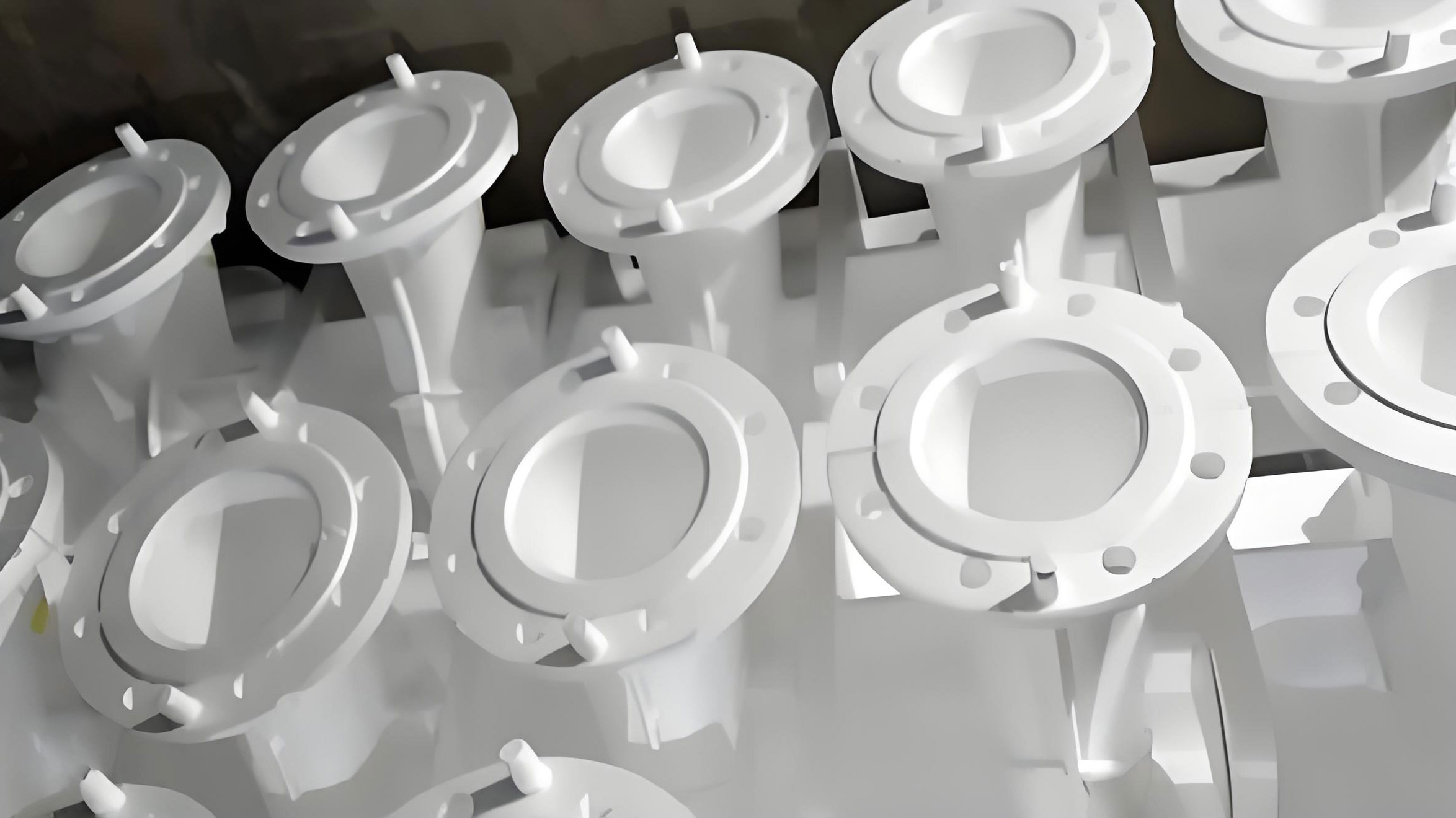
The process flow of lost foam casting can be summarized in a sequence that I use when training new engineers. The pattern shop receives raw beads, pre-expands them, and allows them to mature. The matured beads are injected into molds to form pattern sections. These sections are aged, glued into clusters, coated with refractory slurry, and dried. The dried clusters are sent to the black area, where they are placed in flasks, embedded in dry sand, and compacted on a vibration table. A vacuum is applied, metal is poured, and the foam gasifies. After cooling, the flask is tipped, the sand is separated, and the casting is cleaned. The dry sand is cooled, screened, magnetically cleaned, and returned to the molding line.
I often represent the material flow with a simple mass balance. For a plant producing \(M_{\text{cast}}\) tons of good castings per year, the required foam mass is:
$$ m_{\text{foam}} = \frac{M_{\text{cast}}}{\rho_{\text{metal}} / \rho_{\text{foam}}} $$
This ratio is typically very small because the foam density is much lower than the metal density. However, the foam volume is essentially the same as the casting volume, so the pattern shop must handle large volumes of low-density material. This is why the white area requires substantial floor space and careful ventilation.
White Area Design: Pattern Making and Fire Safety
The white area is the most fire-sensitive part of a lost foam casting plant. The raw beads and the expanded foam are combustible, and the fire hazard classification drives the building design. In my experience, the most common foam materials are expandable polystyrene (EPS), styrene-methyl methacrylate copolymer (STMMA), and expandable polymethyl methacrylate (EPMMA). The table below lists their typical applications.
| Foam Material | Typical Application |
|---|---|
| EPS | Non-ferrous metals, gray iron, general steel castings |
| STMMA | Gray iron, low-carbon steel, alloy steel castings |
| EPMMA | Ductile iron, malleable iron, low-carbon steel, alloy steel, stainless steel |
All of these materials can release flammable vapors. According to the fire code that I follow, the storage room for these beads is classified as a high-hazard occupancy, and the耐火等级 is typically level II. If the high-hazard storage area exceeds 5% of the total workshop area, the entire workshop must be classified as high hazard. This is a critical design constraint. I always calculate the area ratio early in the project:
$$ R_{\text{storage}} = \frac{A_{\text{storage}}}{A_{\text{workshop}}} \times 100\% $$
To avoid reclassifying the entire building, I keep \(R_{\text{storage}}\) below 5%. This often means designing a separate, small storage room with fire-rated walls and independent ventilation. In one project, I reduced the storage area from 8% to 4.5% by using a compact racking system and just-in-time delivery. The savings in fire protection systems were substantial.
The production area of the pattern shop is generally classified as a moderate-hazard occupancy, but it still requires automatic sprinkler systems and indoor hydrants. I also specify fire separation between the pattern shop and the lost foam casting black area. A fire-rated curtain or a water curtain can be used in the connecting corridor. The goal is to prevent a fire in the white area from spreading into the black area, where the dry sand and molten metal present different risks.
In terms of layout, I prefer a multi-story pattern shop. The equipment in the white area is not tall, but it occupies large floor areas for molding machines, aging racks, coating tanks, and drying ovens. A three-story building is often optimal. The ground floor houses pre-expansion, maturation, and molding machines. The second floor contains coating and drying, and it is also the level where the coated clusters are transferred to the black area via an overhead conveyor. The top floor can be a solar aging room, where natural sunlight accelerates the aging of pattern sections. This arrangement reduces the footprint and keeps the building height compatible with the black area.
| Floor | Function | Key Equipment |
|---|---|---|
| Ground floor | Bead pre-expansion, maturation, pattern molding | Pre-expander, fluid bed dryer, molding machines, steam supply |
| Second floor | Coating, drying, cluster assembly, transfer | Coating tanks, drying ovens, glue stations, overhead conveyor |
| Top floor | Pattern aging, solar drying, final gluing | Aging racks, solar room, assembly tables |
The pattern molding process uses steam to heat the beads in the mold. The steam condensate load can be significant. I calculate the condensate flow rate as:
$$ \dot{m}_{\text{cond}} = \frac{Q_{\text{steam}}}{h_{fg}} $$
where \(Q_{\text{steam}}\) is the heat input and \(h_{fg}\) is the latent heat of steam. This helps size the condensate return system and the boiler capacity. I also specify that the boiler house be located close to the pattern shop to minimize steam line losses.
Black Area Design: Molding, Sand Processing, and Vacuum
The black area of a lost foam casting plant resembles a conventional sand foundry in its melting and cleaning operations, but the molding and sand processing are unique. The molding line is built around a vibration table. The dry sand is poured into the flask while the table vibrates, allowing the sand to flow around the pattern cluster and fill all cavities. The vibration parameters must be carefully selected to achieve uniform compaction without deforming the foam pattern. I usually specify a vibration frequency and amplitude that produce a sand density of about 1.5 to 1.6 g/cm³. The compaction can be expressed as:
$$ \rho_{\text{bed}} = \frac{m_{\text{sand}}}{V_{\text{flask}} – V_{\text{pattern}}} $$
where \(m_{\text{sand}}\) is the mass of sand, \(V_{\text{flask}}\) is the flask volume, and \(V_{\text{pattern}}\) is the pattern volume. The vacuum system then holds the sand in place during pouring. The negative pressure must be sufficient to overcome the metallostatic pressure and the gas pressure from foam decomposition. A typical vacuum level is between 0.02 and 0.05 MPa below atmospheric. I use the following relationship to estimate the required vacuum:
$$ P_{\text{vac}} = \rho_{\text{metal}} g h + \Delta P_{\text{coating}} + P_{\text{gas}} $$
where \(\rho_{\text{metal}}\) is the metal density, \(g\) is gravity, \(h\) is the metal head, \(\Delta P_{\text{coating}}\) is the pressure drop across the coating, and \(P_{\text{gas}}\) is the gas pressure from foam decomposition. In my designs, I always include a vacuum pump room adjacent to the pouring line. The vacuum lines should be as short as possible to reduce pressure losses.
The sand processing system in lost foam casting is simpler than in green sand casting because there is no binder. The dry sand is recovered, cooled, screened, and returned. The typical sequence is: hydraulic flask tipper, vibrating conveyor, high-temperature bucket elevator, vibrating screen, magnetic separator, automatic sand gate, fluidized bed cooler, bucket elevator, intermediate sand silo, sand temperature regulator, and molding sand silo. The sand temperature must be controlled because hot sand can soften the foam pattern and cause dimensional errors. I usually target a sand temperature below 50°C. The cooling load is calculated as:
$$ Q_{\text{cool}} = \dot{m}_{\text{sand}} c_{p,\text{sand}} (T_{\text{hot}} – T_{\text{cold}}) $$
where \(\dot{m}_{\text{sand}}\) is the sand circulation rate, \(c_{p,\text{sand}}\) is the specific heat of sand, and \(T_{\text{hot}}\) and \(T_{\text{cold}}\) are the sand temperatures before and after cooling. The cooling water flow rate is then:
$$ \dot{m}_{\text{water}} = \frac{Q_{\text{cool}}}{c_{p,\text{water}} \Delta T_{\text{water}}} $$
I always design the sand processing area with a closed-loop water system to minimize consumption. The sand recovery rate is a key performance indicator. I define it as:
$$ \eta_{\text{sand}} = \frac{m_{\text{recovered}}}{m_{\text{input}}} \times 100\% $$
In a well-operated lost foam casting plant, \(\eta_{\text{sand}}\) exceeds 90%. This reduces both raw material cost and waste disposal.
| Sand Processing Step | Purpose | Key Parameter |
|---|---|---|
| Flask tipping | Discharge sand and casting | Angle and speed |
| Vibrating conveyor | Transport and initial cooling | Stroke and frequency |
| Bucket elevator | Vertical transport | Capacity and temperature rating |
| Vibrating screen | Remove debris and lumps | Mesh size |
| Magnetic separator | Remove metal particles | Magnetic strength |
| Fluidized bed cooler | Cool sand to target temperature | Air flow and water flow |
| Sand temperature regulator | Fine-tune temperature | Set point below 50°C |
| Sand silo | Buffer storage | Level indicators |
The black area also includes melting and cleaning. Melting is similar to any foundry, but I pay attention to pouring temperature because the foam decomposition is endothermic. A slightly higher superheat may be needed to ensure complete filling. Cleaning is easier because there is no sand core and minimal flash. I typically allocate less floor space to cleaning in a lost foam casting plant than in a green sand plant.
Engineering Design Points for Lost Foam Casting Facilities
When I design a lost foam casting facility, I focus on several points that experience has shown to be critical. First, the separation of the white and black areas is essential for fire safety and operational efficiency. The white area has a higher fire hazard, so it should be in a separate building or a separated compartment. The black area is a lower hazard, so keeping the high-hazard area small reduces the overall fire protection cost. I calculate the fire area ratio and ensure it remains below the threshold that triggers a higher hazard classification. This single decision can save significant capital and simplify permitting.
Second, the vacuum system must be designed as an integral part of the molding line. The vacuum pump capacity, pipe diameter, and valve placement all affect the quality of the lost foam casting. I prefer to use a dedicated vacuum pump room for each molding line. The vacuum level is monitored continuously, and the control system adjusts the pump speed to maintain the set point. The following formula helps estimate the pump capacity:
$$ \dot{V}_{\text{pump}} = \frac{Q_{\text{gas}} + Q_{\text{leak}}}{\eta_{\text{vol}}} $$
where \(Q_{\text{gas}}\) is the gas generation rate from foam decomposition, \(Q_{\text{leak}}\) is the leakage rate, and \(\eta_{\text{vol}}\) is the volumetric efficiency. I always add a safety factor of 1.2 to 1.5 to account for variations in foam density and coating permeability.
Third, the sand cooling system must be sized for the maximum sand circulation rate. The sand-to-metal ratio in lost foam casting is typically higher than in green sand casting because the sand is not bonded and must be cooled more aggressively. I use a sand-to-metal ratio of about 4:1 to 6:1 by weight. The cooling water system should include redundancy to avoid downtime. I also specify plate heat exchangers and cooling towers with adequate capacity.
Fourth, automation in the white area is often overlooked. In many existing lost foam casting plants, pattern making is labor-intensive. I believe that future designs must improve automation in bead pre-expansion, molding, gluing, and coating. Robotic handling of pattern sections and automated glue dispensing can reduce labor and improve consistency. The economic benefit can be evaluated by the payback period:
$$ T_{\text{payback}} = \frac{C_{\text{automation}}}{\Delta C_{\text{labor}} + \Delta C_{\text{quality}}} $$
where \(C_{\text{automation}}\) is the capital cost of automation, \(\Delta C_{\text{labor}}\) is the annual labor savings, and \(\Delta C_{\text{quality}}\) is the annual savings from reduced defects. In my analysis, automation in the white area often pays back in two to three years when production volume is high.
| Design Point | Objective | Key Metric |
|---|---|---|
| White/black separation | Reduce fire risk and cost | Storage area ratio below 5% |
| Vacuum system | Ensure mold stability | Vacuum level 0.02–0.05 MPa |
| Sand cooling | Prevent pattern deformation | Sand temperature below 50°C |
| Sand recovery | Reduce material cost | Recovery rate above 90% |
| Automation | Improve consistency | Payback period 2–3 years |
I also consider the building height and crane coverage. The black area typically requires tall bays for melting and pouring. The white area can be lower, but the multi-story arrangement should align with the black area for material flow. I often use an overhead conveyor to transfer coated clusters from the second floor of the pattern shop to the black area. This conveyor must pass through a fire-rated opening with a water curtain or fire shutter. The transfer point is a critical interface that I detail carefully in the design.
Ventilation is another important aspect. The white area needs exhaust ventilation to remove styrene and other volatile organic compounds. The black area needs ventilation for heat, fumes, and dust. I design the ventilation system to maintain a slight negative pressure in the white area relative to the adjacent spaces, so that flammable vapors do not migrate. The air change rate in the pattern shop is usually 6 to 10 air changes per hour. The exhaust air may require treatment depending on local regulations. I often specify activated carbon adsorption or thermal oxidation for the white area exhaust.
Quantitative Summary of Benefits and Design Parameters
To communicate the value of lost foam casting to project stakeholders, I use a set of quantitative indicators. The table below summarizes typical values that I have observed or calculated in my designs.
| Indicator | Typical Value | Formula |
|---|---|---|
| Sand recovery rate | > 90% | $$ \eta_{\text{sand}} = \frac{m_{\text{recovered}}}{m_{\text{input}}} \times 100\% $$ |
| Energy cost reduction | ~15% | $$ \eta_{\text{energy}} = \frac{E_{\text{green sand}} – E_{\text{lost foam}}}{E_{\text{green sand}}} \times 100\% $$ |
| Casting cost reduction | ~30% | $$ \eta_{\text{cost}} = \frac{C_{\text{green sand}} – C_{\text{lost foam}}}{C_{\text{green sand}}} \times 100\% $$ |
| Cleaning labor reduction | > 50% | $$ \eta_{\text{cleaning}} = \frac{L_{\text{green sand}} – L_{\text{lost foam}}}{L_{\text{green sand}}} \times 100\% $$ |
| Equipment investment reduction | 30–50% | $$ \eta_{\text{investment}} = \frac{I_{\text{green sand}} – I_{\text{lost foam}}}{I_{\text{green sand}}} \times 100\% $$ |
| Storage area ratio | < 5% | $$ R_{\text{storage}} = \frac{A_{\text{storage}}}{A_{\text{workshop}}} \times 100\% $$ |
| Vacuum level | 0.02–0.05 MPa | $$ P_{\text{vac}} = P_{\text{atm}} – P_{\text{abs}} $$ |
| Sand temperature | < 50°C | $$ T_{\text{sand}} = T_{\text{hot}} – \frac{Q_{\text{cool}}}{\dot{m}_{\text{sand}} c_{p,\text{sand}}} $$ |
These indicators help me justify the choice of lost foam casting for a given project. For example, if a customer is producing complex motor housings, the reduction in cleaning labor and the elimination of cores can reduce the total manufacturing cost by about 30%. The environmental benefits are also significant: less waste sand, lower emissions, and lower energy consumption. I have found that lost foam casting is particularly competitive when the production volume is moderate to high and the casting geometry is complex.
Detailed Design Calculations for a Representative Project
To illustrate my approach, I will walk through a simplified design calculation for a lost foam casting plant producing 5,000 tons of gray iron castings per year. The plant operates 300 days per year, two shifts per day, and 8 hours per shift. The effective production time is:
$$ t_{\text{year}} = 300 \times 2 \times 8 = 4800 \text{ hours} $$
The required production rate is:
$$ \dot{M} = \frac{5000}{4800} \approx 1.04 \text{ t/h} $$
Assuming a sand-to-metal ratio of 5:1, the sand circulation rate is:
$$ \dot{m}_{\text{sand}} = 5 \times 1.04 = 5.2 \text{ t/h} $$
The sand must be cooled from 120°C to 45°C. The specific heat of sand is about 0.8 kJ/(kg·K). The cooling load is:
$$ Q_{\text{cool}} = 5.2 \times 1000 \times 0.8 \times (120 – 45) / 3600 \approx 86.7 \text{ kW} $$
Using cooling water with a temperature rise of 10°C and a specific heat of 4.18 kJ/(kg·K), the water flow rate is:
$$ \dot{m}_{\text{water}} = \frac{86.7}{4.18 \times 10} \approx 2.07 \text{ kg/s} \approx 7.5 \text{ m}^3/\text{h} $$
For the vacuum system, I assume a gas generation rate of 0.5 m³ per kg of foam, and the foam mass is about 1% of the casting mass. The foam consumption rate is:
$$ \dot{m}_{\text{foam}} = 0.01 \times 1.04 \times 1000 = 10.4 \text{ kg/h} $$
The gas generation rate is:
$$ Q_{\text{gas}} = 10.4 \times 0.5 = 5.2 \text{ m}^3/\text{h} $$
Adding a leakage allowance of 20% and a safety factor of 1.5, the required pump capacity is:
$$ \dot{V}_{\text{pump}} = 1.5 \times (5.2 \times 1.2) \approx 9.4 \text{ m}^3/\text{h} $$
This is a modest requirement, but I would select a pump with at least 20 m³/h capacity to allow for process variations. The vacuum receiver and piping should be sized to minimize pressure fluctuations.
For the pattern shop, the required floor area depends on the molding machine cycle time and the number of patterns. I typically estimate the area using a production rate model:
$$ A_{\text{pattern}} = \frac{N_{\text{machines}} A_{\text{machine}} + A_{\text{aging}} + A_{\text{coating}}}{ \eta_{\text{space}} } $$
where \(N_{\text{machines}}\) is the number of molding machines, \(A_{\text{machine}}\) is the area per machine, \(A_{\text{aging}}\) is the aging area, \(A_{\text{coating}}\) is the coating area, and \(\eta_{\text{space}}\) is the space utilization factor (typically 0.6 to 0.7). For a 5,000 t/year plant, I might need 4 to 6 molding machines, each occupying about 20 m², an aging area of 200 m², and a coating area of 150 m². The total pattern shop area would be around 800 to 1,000 m². A three-story building with 350 m² per floor would be sufficient.
| Parameter | Value | Unit |
|---|---|---|
| Annual production | 5,000 | t/year |
| Operating hours | 4,800 | h/year |
| Production rate | 1.04 | t/h |
| Sand circulation rate | 5.2 | t/h |
| Cooling load | 86.7 | kW |
| Cooling water flow | 7.5 | m³/h |
| Foam consumption | 10.4 | kg/h |
| Gas generation | 5.2 | m³/h |
| Vacuum pump capacity | 20 | m³/h |
| Pattern shop area | 1,000 | m² |
These calculations are the backbone of my engineering design. They allow me to size equipment, estimate utility requirements, and lay out the plant. Of course, actual designs require more detailed simulations and vendor data, but these preliminary calculations guide the concept.
Safety, Environmental, and Operational Considerations
Safety is paramount in lost foam casting. The foam materials are flammable, and the molten metal is hazardous. I design the plant with clear separation between the white and black areas, fire-rated walls, and automatic sprinkler systems. The vacuum system must be interlocked with the pouring system to prevent metal spillage if the vacuum fails. The sand system must be grounded to prevent static electricity. I also specify gas detection in the pattern shop to monitor styrene levels. The ventilation system should be designed to keep concentrations below the occupational exposure limits.
Environmental compliance is another driver. Lost foam casting produces less waste sand and fewer emissions than green sand casting, but the white area still emits volatile organic compounds. I often use regenerative thermal oxidizers or activated carbon filters to treat the exhaust. The sand reclamation system reduces the need for new sand and lowers disposal costs. The energy savings of about 15% also reduce the carbon footprint. I have found that these environmental benefits are increasingly important to clients and regulators.
Operationally, I emphasize training and standard operating procedures. The lost foam casting process is sensitive to small changes in foam density, coating thickness, sand temperature, and vacuum level. A well-trained workforce can maintain the process window and achieve consistent quality. I recommend installing a supervisory control and data acquisition system to monitor key variables and provide alarms. The data can also be used for continuous improvement. For example, by tracking the relationship between vacuum level and defect rate, I can optimize the vacuum set point and reduce scrap.
Future Trends in Lost Foam Casting Design
Looking ahead, I see several trends that will shape the future of lost foam casting. First, automation in the white area will increase. Robotic handling, automated gluing, and inline inspection will reduce labor and improve quality. Second, simulation will become more integrated. Computational fluid dynamics and heat transfer models can predict foam decomposition, metal filling, and solidification. This will allow engineers to optimize coating permeability and vacuum profiles before cutting metal. Third, new foam materials with lower density and lower ash content will improve casting quality and reduce emissions. Fourth, energy recovery systems will capture waste heat from the cooling sand and the melting furnace, further improving energy efficiency. I believe that lost foam casting will continue to grow because it aligns with the industry’s need for complex, lightweight, and cost-effective castings.
In my own practice, I am already incorporating these trends. I use simulation to evaluate gating and vacuum design. I specify automated glue dispensing and robotic handling where the production volume justifies it. I design heat recovery systems for sand cooling and furnace exhaust. These measures not only improve the process but also make the lost foam casting plant more sustainable and competitive.
Conclusion
Lost foam casting is a versatile and efficient process that offers significant advantages over conventional sand casting. From my perspective as an engineering designer, the key points are the separation of the white and black areas, the control of fire hazards, the design of the vacuum system, and the optimization of sand processing. By using quantitative tools such as the formulas and tables presented here, I can size equipment, estimate costs, and lay out a plant that meets production, safety, and environmental goals. The process is particularly suited to complex castings, and its benefits include reduced cleaning labor, lower energy consumption, and higher sand recovery. As the industry moves toward greener and more efficient manufacturing, lost foam casting will play an increasingly important role. I am confident that with careful engineering design, lost foam casting projects can achieve excellent returns and long-term operational success.