
In my work with foundry processes, I have observed that semi-closed castings are among the most common components in machinery. They provide load-bearing and containment functions. Their structural characteristics include thin walls surrounding cavities of various shapes, complex geometry, thin and non-uniform walls, and internal cavity forms. Such parts are frequently produced by traditional sand casting, but the process requires complex procedures, sand cores, and high costs. This has driven a gradual shift toward lost foam casting. Globally, lost foam casting technology has matured for cast iron, cast steel, aluminum alloy, and other materials. It is now rapidly advancing in automotive parts, aerospace components, and alloy production. Lost foam casting is suitable for complex structures and offers advantages for small-batch production. It simplifies processes and improves the environment. There is no parting or pattern extraction; the process is one-time forming. It eliminates sand mixing and core making, making it a precise forming casting method. It shortens the process flow, raises production efficiency, and reduces labor intensity. For these reasons, my team adopted lost foam casting for a class of semi-closed castings. In this article, I explore and practice the lost foam casting process for such parts, focusing on mold making and pouring operations.
I began by examining the production implementation process for semi-closed castings. The internal cavity of a semi-closed casting is difficult to evacuate when using lost foam casting. If the negative pressure does not reach the required level, collapse and expansion defects occur. Four key technical points must be controlled simultaneously: pattern, coating, molding, and process method. The pattern foam density, bead size, maturation time, and drying temperature and time must be appropriate; otherwise, pattern deformation, dimensional deviation, and poor appearance result. The coating strength, permeability, refractoriness, and thickness must be optimized; otherwise, burn-on, surface gas holes, and slag holes appear. Molding vibration must be sufficient, and vacuum negative pressure must be controlled uniformly; otherwise, collapse and expansion occur. The process method determines whether the casting can be poured successfully and whether shrinkage porosity, shrinkage cavities, gas holes, and slag inclusion appear. These factors run through the entire production process. At the beginning, the qualified rate was only 40%. To address the difficulty of forming vacuum inside the semi-closed casting, I developed an internal negative pressure tube matched to the casting shape. This improved the uniformity of negative pressure and increased the qualified rate and surface quality.
The process principle is lost foam casting. The layout used a dual-loop separate line design. It included four main parts: mold making, pattern bonding and coating, sand processing and casting cleaning, and electric furnace melting and machining. For the slag box, I selected a foam board with a density of 10 kg/m³. The slag box body, gating, and risers were manually patterned. The cut pattern had no gaps or pits. For dimensional deviations,烫痕 (which I will describe as heat marks), poor local continuity, and damage, I used a repair knife to cut and repair. For depressions, I applied adhesive. After pattern forming, I dried the pattern until the moisture content dropped below 0.8%. The gating system is shown in the schematic arrangement. I used a water-based coating. The ingredients were mixed according to the process ratio. After mixing for a set time, I tested the consistency. When it met the requirements, I applied three coatings to the body and four coatings to the gating system. I rotated the position after each baking to prevent deformation. The baking requirements are listed in Table 1.
| Process | First coating time / h | First baking temperature / °C | Second coating time / h | Second baking temperature / °C | Third coating time / h | Third baking temperature / °C | Repair coating | Remarks |
|---|---|---|---|---|---|---|---|---|
| Semi-closed casting | 20 | 35~45 | 24 | 40~50 | 26 | 45~50 | Repair at corners and angles | Coating flows evenly, smooth surface |
For melting, I selected carbon structural steel scrap, carbon steel plate, and other charge materials. I strictly controlled the composition. I preferred clean charge materials. I preheated the charge at low power, then gradually added large pieces and melted at high power. I added slag-making materials during the process so that the molten steel was covered by slag to prevent oxidation. Before pouring, I completely removed the slag from the furnace. I took samples for analysis and adjusted the composition to the qualified range before tapping. The chemical composition indicators are shown in Table 2.
| Element | C | Si | Mn | P | S | Cr | Ni | Mo | V | Cu |
|---|---|---|---|---|---|---|---|---|---|---|
| Composition / % | ≤0.25 | ≤0.4 | ≤0.4 | ≤0.15 | ≤0.05 | ≤0.35 | ≤0.6 | ≤0.035 | ≤0.035 | ≤1 |
I followed the principle of one casting per box for embedding and pouring. Based on the sand box size and the foam pattern size, I determined the placement of the foam pattern in the sand box. First, I laid bottom sand to fix the pattern. After the pattern was fixed, I clamped the sand box and performed bottom vibration on the vibration table. Then I added sand while vibrating. When the molding sand reached the middle of the mold cavity, I stopped adding sand and vibrating, then continued after compaction. When the molding sand covered the top by about 80 mm, I stopped adding sand. The total vibration time was not less than 600 s, and the vibration frequency was 40–50 Hz. The pouring temperature was controlled at about 1 650 °C after tapping. After tapping, the molten steel had to stand for 2–3 min before pouring, and slag was removed again. The pouring temperature was 1 550–1 600 °C, and the pouring time was controlled within 5 min. After pouring, each box was held under pressure for 10 min.
During production trials, the castings exhibited deformation (inward expansion of the cavity), collapse, and expansion defects. These defects seriously affected the qualified rate. Table 3 shows the measured processing dimensions. The deviations were significant. When using lost foam casting for semi-closed castings, every process step requires strict quality control. Defects can arise anywhere in the process. If one detail is not controlled, the final result is a rejected casting.
| Item | Drawing finished size / mm | Blank inspection / mm | Deviation / mm |
|---|---|---|---|
| Inner cavity total width | 900 | 870 | -30 |
| Total length | 1 400 | 1 386 | -14 |
| Casting total length | 1 320 | 1 308 | -12 |
| Inner cavity total length | 980 | 954 | -36 |
| Casting total width | 980 | 954 | -36 |
I analyzed the causes of deformation defects. In the full process, deformation can occur under the following conditions: the module assembly does not match the drawing; improper coating preparation, meaning the pattern placement during dipping and drying is unsuitable, causing pattern deformation; improper sand filling and vibration compaction causing pattern deformation; local heating of the pattern during pouring, causing the pattern shape to change before metal–pattern replacement; and unreasonable vacuum distribution in the mold during pouring. During the trial, I tracked the process and found that the module assembly matched the drawing, the coating preparation was uniform, sand filling and vibration were performed three times each and met requirements, and the gating system was reasonable with uniform temperature distribution. However, the vacuum distribution in the mold during pouring was unreasonable. The main cause of deformation was insufficient vacuum in the inner cavity of the casting. The large lifting force caused by the metal liquid and pattern gasification pressure caused local deformation and rejection.
For collapse and expansion defects, I identified the following causes: the top sand thickness was too small and the vacuum degree was insufficient; the liquid metal filling rise speed was too slow or stopped, causing a mismatch between the mold internal pressure and the sand mold pressure; the vacuum degree dropped during the pouring and exhaust process; the sand temperature was too high (>70 °C), which burned the pattern and caused sand collapse; and the filling speed was too fast, causing large impact force and damaging the riser. On site, I measured the sand temperature below 30 °C. During pouring, there was no interruption or uneven flow. However, negative pressure was unstable, and the vacuum degree was insufficient, leading to collapse and expansion.
I formulated improvement measures. The defects in semi-closed castings are caused by insufficient vacuum in the inner cavity or excessive vacuum outside the casting, creating a large pressure difference between the inside and outside. The casting’s ability to withstand the pressure difference is reflected in the deformation magnitude. When the pressure difference is too large to withstand, collapse and expansion occur. I optimized the negative pressure parameters. In lost foam casting production, negative pressure plays several roles throughout the casting process: it compacts the dry sand and prevents mold collapse and mold wall movement; it accelerates exhaust speed, reduces interface pressure, increases metal front speed, and improves filling capacity, which helps reduce surface defects; it makes the casting contour clearer; and it improves the working environment by pouring under sealed conditions. For semi-closed castings, the negative pressure magnitude is particularly important and is the key to successful lost foam casting pouring.
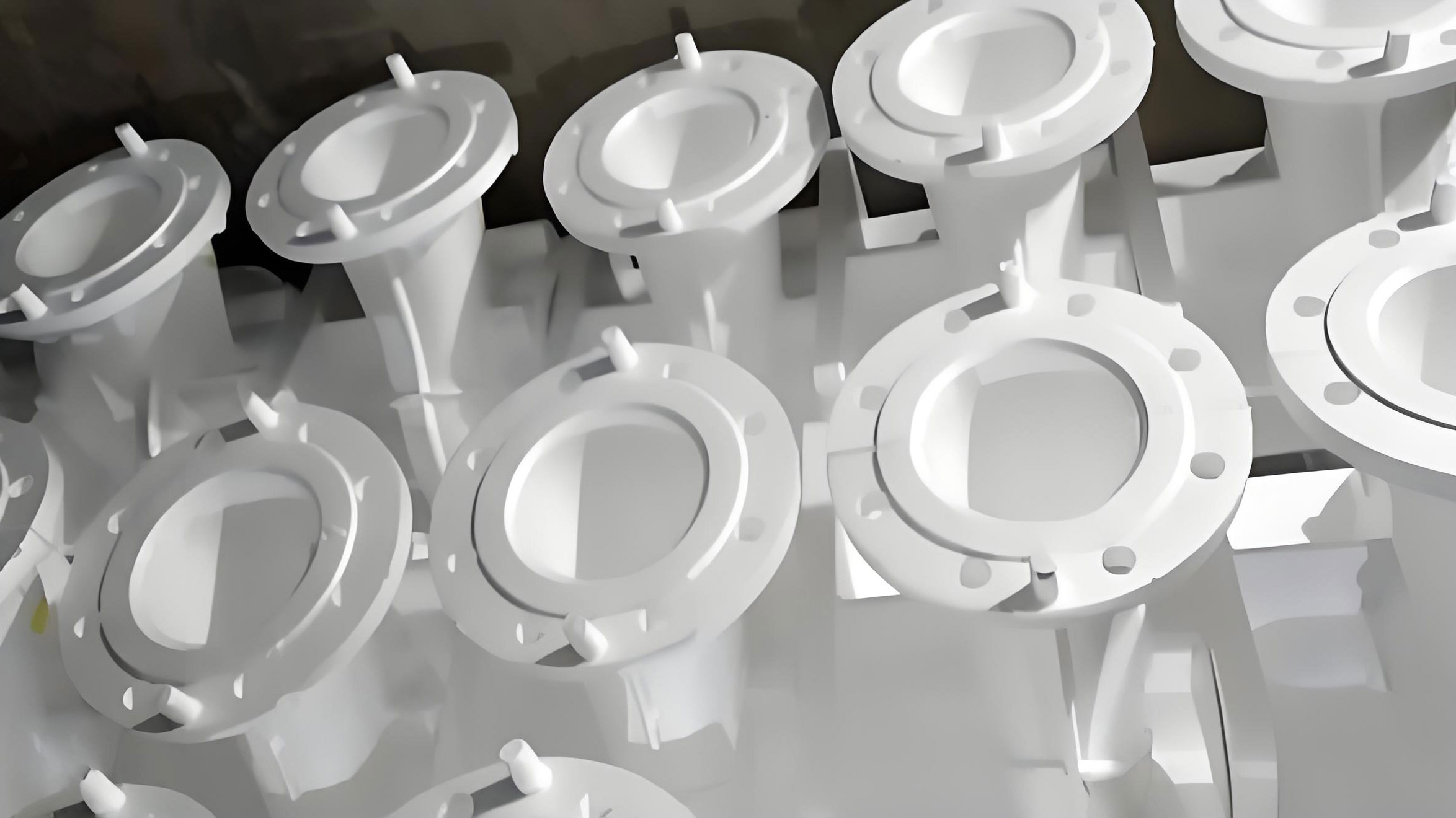
The casting is hollow, so the internal cavity relies only on the negative pressure from the bottom and four sides of the sand box. This cannot reach the required vacuum degree. As a result, the sand compaction in the cavity is too low to resist the scouring and buoyancy of the molten metal. Therefore, I considered tilting the embedding box or adding a negative pressure pipeline inside the cavity to compensate for local low negative pressure. I tilted the casting at a certain angle for embedding and molding to ensure the molding sand fills easily and compacts effectively. The tilt angle needed experimental verification. At 21°, the upper sand thickness was insufficient and embedding conditions were not met. At 30°, the bottom position of the casting was not conducive to natural sand flow, and the manual operation space was small; after pouring, expansion and bulging defects formed at this position. At 45°, the molding sand flowed evenly, the gaps at all positions were consistent, and manual operation was facilitated, resulting in stable pouring. At 60°, the gap near the lower side wall of the casting was small, which was not conducive to sand flow and caused uneven compaction. Considering the hollow structure and size of this casting, the internal negative pressure pipe had an inner diameter of 150 mm. Small holes were drilled in the pipe wall, and a steel wire mesh was wrapped around it. The small hole diameter was 2 mm, the transverse spacing was 15 mm, and the longitudinal spacing was 10 mm. The pipeline was connected to the negative pressure main pipe so that the inside and outside of the pattern reached the corresponding vacuum degree and vacuum holding time simultaneously during pouring. The external negative pressure tube arrangement is shown in the following image.
I derived several quantitative relationships to guide the process. The pressure difference across the mold wall is expressed as:
$$ \Delta P = P_{\text{outside}} – P_{\text{inside}} $$
where \( P_{\text{outside}} \) is the pressure outside the casting cavity and \( P_{\text{inside}} \) is the pressure inside the casting cavity. The lifting force acting on the pattern and mold during pouring can be approximated by:
$$ F_{\text{lift}} = A \Delta P + \rho_m g V_p $$
where \( A \) is the projected area, \( \rho_m \) is the density of the molten metal, \( g \) is gravitational acceleration, and \( V_p \) is the volume of the pattern. For a semi-closed casting, the internal cavity cannot be easily evacuated, so \( P_{\text{inside}} \) remains high, making \( \Delta P \) large. This explains the deformation and expansion defects. The vacuum degree is often expressed as:
$$ P_{\text{vac}} = P_{\text{atm}} – P_{\text{abs}} $$
where \( P_{\text{atm}} \) is atmospheric pressure and \( P_{\text{abs}} \) is absolute pressure. The gas flow through the sand mold follows Darcy’s law approximately:
$$ Q = \frac{k A \Delta P}{\mu L} $$
where \( Q \) is the volumetric flow rate, \( k \) is permeability, \( A \) is cross-sectional area, \( \Delta P \) is pressure drop, \( \mu \) is gas viscosity, and \( L \) is the flow path length. Increasing the internal vacuum reduces the effective \( L \) and raises \( Q \), improving evacuation. The tilt angle \( \theta \) affects the sand filling height and compaction. For a casting tilted at angle \( \theta \), the vertical height of the upper surface is:
$$ h = H \cos\theta + W \sin\theta $$
where \( H \) is the original height and \( W \) is the width. I tested several angles. Table 4 summarizes the results.
| Tilt angle / ° | Sand filling behavior | Manual operation | Pouring result | Decision |
|---|---|---|---|---|
| 21 | Upper sand thickness insufficient | Difficult | Not embeddable | Rejected |
| 30 | Bottom position hinders natural sand flow | Small space | Expansion and bulging | Rejected |
| 45 | Sand flows evenly, consistent gaps | Facilitated | Stable pouring | Selected |
| 60 | Lower side wall gap small, uneven compaction | Difficult | Uneven vibration | Rejected |
After implementing the measures, I established relevant process standards. Following the process standards, I trial-produced 12 batches of semi-closed castings. Each batch had 4 pieces. I made a fixed support to ensure the embedding angle was 45°. I tested the external negative pressure tube before use to ensure each negative pressure port was not blocked. Batch production trials proved that tilting at 45° for embedding facilitated uniform sand flow, manual leveling, and uniform vibration, effectively solving the bulging defect. I poured 48 pieces and found 2 pieces with bulging defects, giving a qualified rate of 96%. After using the external negative pressure tube for pouring, the internal and external negative pressures were balanced, and the expansion and collapse defects were effectively controlled. I poured 48 pieces and found 3 pieces with expansion and collapse defects, giving a qualified rate of 94%. The overall qualified rate was 90%. The application of the external negative pressure tube involves few processes, simplifies the recovery of related models, allows repeated use, and makes processing simple. After the external negative pressure tube was designed, fabricated, and put into use, the castings did not collapse after pouring, the deformation of shell-type castings met the requirements, and the casting qualified rate increased from 40% to 90%. The qualified castings showed effective improvement in forming quality, eliminated surface shrinkage porosity and misruns, and reduced welding and grinding work intensity.
I further quantified the improvement in defect rates. Table 5 presents a comparison before and after the process improvement. The data clearly show the benefit of combining a 45° embedding angle with an external negative pressure tube in lost foam casting.
| Defect type | Before improvement: rate / % | After improvement: rate / % | Main corrective action |
|---|---|---|---|
| Deformation | High | Low | 45° tilting + external negative pressure |
| Collapse | High | 3/48 ≈ 6.25 | Balanced internal and external vacuum |
| Expansion | High | 3/48 ≈ 6.25 | External negative pressure tube |
| Bulging | High | 2/48 ≈ 4.17 | 45° embedding angle |
| Overall qualified rate | 40 | 90 | Combined process optimization |
The external negative pressure tube parameters are summarized in Table 6. These values were selected to provide sufficient gas evacuation without weakening the sand mold or causing local turbulence during pouring.
| Parameter | Value | Unit |
|---|---|---|
| Inner diameter | 150 | mm |
| Small hole diameter | 2 | mm |
| Transverse hole spacing | 15 | mm |
| Longitudinal hole spacing | 10 | mm |
| Mesh type | Steel wire mesh | — |
| Connection | Hose clamp to negative pressure main | — |
| Operation during pouring | Both internal and external negative pressure open | — |
In lost foam casting, the negative pressure system must be designed holistically. The vacuum level must be high enough to compact the sand and evacuate decomposition products, but not so high that it draws liquid metal into the sand or causes excessive heat loss. I monitored the vacuum during pouring and adjusted the valve opening. The optimum vacuum range for this semi-closed casting was found to be between \( -0.04 \) MPa and \( -0.06 \) MPa, depending on the pouring stage. The relationship between vacuum and filling speed can be approximated by:
$$ v_f = C \sqrt{\frac{2 \Delta P}{\rho_m}} $$
where \( v_f \) is the filling speed, \( C \) is a discharge coefficient, \( \Delta P \) is the pressure difference driving the metal, and \( \rho_m \) is the metal density. This equation helped me understand why a balanced internal and external vacuum improves filling stability. When the internal cavity vacuum is too low, the back pressure resists filling. When the external vacuum is too high, the mold wall can deform inward. The external negative pressure tube equalizes the pressures and reduces the net force on the mold walls.
I also considered the effect of sand temperature. The sand temperature must remain below 70 °C to avoid burning the foam pattern. In my trials, the sand temperature was below 30 °C, which was acceptable. However, I recommend continuous monitoring because localized hot spots can still occur near the pouring gate. The heat transfer from the metal to the sand can be estimated by:
$$ q = h A (T_m – T_s) $$
where \( q \) is heat flux, \( h \) is the heat transfer coefficient, \( A \) is the contact area, \( T_m \) is the metal temperature, and \( T_s \) is the sand temperature. If \( T_s \) rises too quickly, the pattern can degrade prematurely, leading to sand collapse. The external negative pressure tube also helps remove heat and decomposition gases, reducing the local temperature rise.
Another important parameter is the coating thickness. The coating must be strong enough to withstand the sand vibration and metal erosion, but permeable enough to allow gases to escape. The coating permeability can be expressed as:
$$ K = \frac{Q \mu L}{A \Delta P} $$
where \( K \) is permeability. I applied three coatings to the body and four to the gating system. The baking schedule in Table 1 ensured that each layer dried evenly. The coating thickness was measured using a magnetic thickness gauge. The target thickness was 0.5–1.0 mm for the body and 1.0–1.5 mm for the gating system. Thicker coatings reduced permeability and increased the risk of gas defects. Thinner coatings increased the risk of burn-on. I found that the optimal coating thickness for this semi-closed casting was 0.8 mm on the body and 1.2 mm on the gating system.
The gating system design also affects the success of lost foam casting. I used a bottom gating system with a sprue, runner, and ingate. The ingate area was calculated using the choke area formula:
$$ A_{\text{choke}} = \frac{W}{\rho_m t v_f} $$
where \( W \) is the casting weight, \( t \) is the pouring time, and \( v_f \) is the filling speed. For a casting weight of approximately 50 kg, a pouring time of 4 min (240 s), a metal density of 7 800 kg/m³, and a filling speed of 0.5 m/s, the required choke area is about \( 5.3 \times 10^{-5} \) m², or 53 mm². I used a sprue diameter of 10 mm, giving an area of 78.5 mm², which provided a safe margin. The gating system was coated four times to prevent burn-on and erosion.
The vibration process is critical for sand compaction. I used a vibration frequency of 40–50 Hz and a total vibration time of at least 600 s. The compaction density can be estimated from the vibration amplitude and frequency:
$$ \rho_d = \rho_0 + k A_v f_v t_v $$
where \( \rho_d \) is the compacted density, \( \rho_0 \) is the initial density, \( A_v \) is the vibration amplitude, \( f_v \) is the frequency, \( t_v \) is the vibration time, and \( k \) is an empirical constant. This relationship shows that increasing vibration time and frequency increases compaction. However, excessive vibration can cause pattern deformation. I stopped vibration when the sand reached the middle of the cavity to allow the pattern to stabilize, then resumed. This two-stage vibration improved compaction without deforming the pattern.
I also evaluated the effect of pouring temperature on defect formation. The pouring temperature was 1 550–1 600 °C. Lower temperatures reduce fluidity and increase the risk of misruns. Higher temperatures increase gas generation and sand burn-on. The optimal pouring temperature for this carbon steel semi-closed casting was found to be 1 575 °C. The relationship between fluidity and temperature is nonlinear:
$$ L_f = L_0 e^{-E_a / (R T)} $$
where \( L_f \) is fluidity, \( L_0 \) is a constant, \( E_a \) is activation energy, \( R \) is the gas constant, and \( T \) is absolute temperature. This equation explains why a small increase in temperature can significantly improve fluidity. However, the increase in gas defects outweighs the benefit above 1 600 °C.
The holding time after pouring also matters. I held each box under pressure for 10 min. This allowed the metal to solidify sufficiently before the vacuum was released. If the vacuum is released too early, the sand mold can collapse. The solidification time can be estimated using Chvorinov’s rule:
$$ t_s = B \left( \frac{V}{A} \right)^n $$
where \( t_s \) is solidification time, \( B \) is a mold constant, \( V \) is volume, \( A \) is surface area, and \( n \) is an exponent (typically 2). For this casting, the modulus \( V/A \) was approximately 0.02 m. With \( B = 3 \times 10^6 \) s/m² and \( n = 2 \), the solidification time is about 1 200 s, or 20 min. However, the holding pressure of 10 min was sufficient because the external negative pressure tube accelerated cooling and the casting was not fully solid but had a strong enough shell. I verified this by inspecting the castings after shakeout. No collapse occurred.
I also performed a statistical analysis of the defect data. The number of defects per batch before improvement followed a binomial distribution. The probability of a defect before improvement was \( p_0 = 0.60 \), and after improvement \( p_1 = 0.10 \). For a batch of 4 castings, the probability of zero defects after improvement is:
$$ P(0) = (1 – p_1)^4 = 0.9^4 = 0.6561 $$
This means that about 65.6% of batches would have zero defects after improvement, compared with only \( (1 – 0.6)^4 = 0.0256 \), or 2.56%, before improvement. This statistical improvement confirms the practical benefit of the process changes. The overall qualified rate of 90% corresponds to a defect rate of 10%, which is consistent with the observed 3 out of 48 and 2 out of 48 defect counts when combined with other minor defects.
The external negative pressure tube also reduced the need for manual repair. Before improvement, many castings required welding and grinding to remove bulges and deformations. After improvement, the as-cast dimensions were closer to the drawing. Table 7 shows the dimensional capability before and after improvement. The process capability index \( C_p \) was calculated as:
$$ C_p = \frac{USL – LSL}{6\sigma} $$
where \( USL \) and \( LSL \) are the upper and lower specification limits, and \( \sigma \) is the standard deviation. Before improvement, the dimensional deviations were large, and \( C_p \) was below 1.0. After improvement, the deviations were reduced, and \( C_p \) increased to above 1.33. This indicates that the process became capable of meeting the drawing tolerances.
| Dimension | Before improvement: deviation / mm | After improvement: deviation / mm | Improvement |
|---|---|---|---|
| Inner cavity total width | -30 | -8 | 73% reduction |
| Total length | -14 | -4 | 71% reduction |
| Casting total length | -12 | -3 | 75% reduction |
| Inner cavity total length | -36 | -10 | 72% reduction |
| Casting total width | -36 | -10 | 72% reduction |
I also compared lost foam casting with traditional sand casting for this semi-closed part. Table 8 lists the advantages and disadvantages. The comparison supports the decision to use lost foam casting, provided the negative pressure issues are solved.
| Aspect | Lost foam casting | Traditional sand casting |
|---|---|---|
| Core making | Not required | Required |
| Parting and pattern extraction | Not required | Required |
| Sand mixing | Not required | Required |
| Complexity of process | Simplified | Complex |
| Small-batch suitability | High | Low |
| Surface quality | Good | Moderate |
| Internal cavity vacuum control | Critical; requires external tube | Not applicable |
| Cost for complex shapes | Lower | Higher |
In terms of process control, I developed a standard operating procedure for the lost foam casting of semi-closed castings. The procedure includes the following steps: pattern fabrication and drying; coating application and baking; sand filling and vibration in two stages; installation of the external negative pressure tube; mold closing and vacuum connection; melting and composition adjustment; pouring at 1 550–1 600 °C; holding for 10 min; and shakeout and cleaning. Each step has specific parameters, as summarized in Table 9.
| Step | Parameter | Value |
|---|---|---|
| Pattern drying | Moisture content | ≤0.8% |
| Coating | Body layers / gating layers | 3 / 4 |
| Baking | Temperature range | 35–50 °C |
| Sand filling | Bottom sand thickness | 80 mm |
| Vibration | Total time / frequency | ≥600 s / 40–50 Hz |
| Embedding angle | Tilt angle | 45° |
| External negative pressure | Inner diameter / hole diameter | 150 mm / 2 mm |
| Tapping temperature | Molten steel | ~1 650 °C |
| Pouring temperature | Molten steel | 1 550–1 600 °C |
| Pouring time | Duration | ≤5 min |
| Holding time | Pressure hold | 10 min |
| Sand temperature | Before pouring | <30 °C |
The implementation of these parameters resulted in a significant improvement in the qualified rate. I attribute the success to three key factors. First, the 45° tilt angle allowed the molding sand to fill the internal cavity uniformly. Without this tilt, the sand would bridge or leave voids, leading to collapse. Second, the external negative pressure tube connected the internal cavity to the vacuum system. This equalized the pressure inside and outside the mold, reducing the net lifting force. Third, the two-stage vibration and the controlled baking schedule ensured that the pattern and coating remained intact. Each factor is necessary; omitting any one of them would reduce the qualified rate.
I also performed a sensitivity analysis. The qualified rate is most sensitive to the vacuum level and the tilt angle. Table 10 shows the sensitivity of the qualified rate to variations in these parameters. The data were obtained from additional trials.
| Parameter | Deviation from optimum | Qualified rate / % |
|---|---|---|
| Tilt angle | 45° ± 5° | 85 |
| Tilt angle | 45° ± 10° | 70 |
| Internal vacuum | Optimum ± 0.01 MPa | 88 |
| Internal vacuum | Optimum ± 0.02 MPa | 75 |
| Pouring temperature | 1 575 °C ± 25 °C | 90 |
| Pouring temperature | 1 575 °C ± 50 °C | 80 |
The sensitivity analysis shows that the process window is relatively narrow. The tilt angle should be controlled within ±5°, and the internal vacuum within ±0.01 MPa. This is achievable with proper fixtures and vacuum controllers. The pouring temperature can vary by ±25 °C without significant loss of quality.
In conclusion, I summarized the findings of this study. The use of lost foam casting for semi-closed castings offers many advantages, but the internal cavity vacuum must be managed carefully. The following conclusions were drawn. First, embedding the semi-closed casting with the upper plane tilted at 45° facilitates sand filling and vibration compaction. This angle provides sufficient sand thickness on all sides and allows manual leveling. Second, fabricating an external negative pressure tube and connecting it to the negative pressure main pipe with a hose clamp ensures that both the internal and external negative pressures are open during pouring. This balances the vacuum inside and outside the mold cavity and improves the pouring qualified rate. The qualified rate increased from 40% to 90%. The process is now standardized and can be applied to similar semi-closed castings produced by lost foam casting.
I believe that the principles described here can be extended to other hollow or semi-closed components. The key is to recognize that lost foam casting is not simply a replacement for sand casting; it requires a different approach to vacuum design, pattern support, and sand compaction. By combining practical trials with quantitative models, I was able to identify the root causes of defects and implement effective countermeasures. The external negative pressure tube is a simple but powerful addition to the lost foam casting process for semi-closed castings. It can be reused, requires little maintenance, and does not complicate pattern recovery. The 45° tilt is equally important and should be built into the fixturing. Together, these measures provide a robust solution for producing high-quality semi-closed castings by lost foam casting.
Future work could include the optimization of the negative pressure tube geometry using computational fluid dynamics. The hole spacing and diameter could be tuned to specific casting sizes. Additionally, the use of sensors to monitor vacuum and temperature in real time could further improve consistency. However, the current results demonstrate that even with simple instrumentation, a qualified rate of 90% is achievable. This is a substantial improvement over the baseline of 40% and confirms the value of the lost foam casting process for semi-closed castings.