
Aluminum door bodies sit at the intersection of two engineering pressures: mass reduction and structural stiffness. A door body accounts for roughly half of a complete door assembly, so replacing a stamped-and-welded steel structure with a thin-wall aluminum casting can remove hem flanges, fasteners, and multiple welded reinforcements. The lightweighting case is often expressed with a simple estimate: every 100 kg removed from a vehicle saves about 0.3–0.6 L/100 km of fuel, adds roughly 20 km of electric range, and avoids about 5–8 g/km of CO2. By mid-2021, China’s vehicle parc was already close to 300 million units, which explains why door-body mass has become a practical target rather than a marginal one.
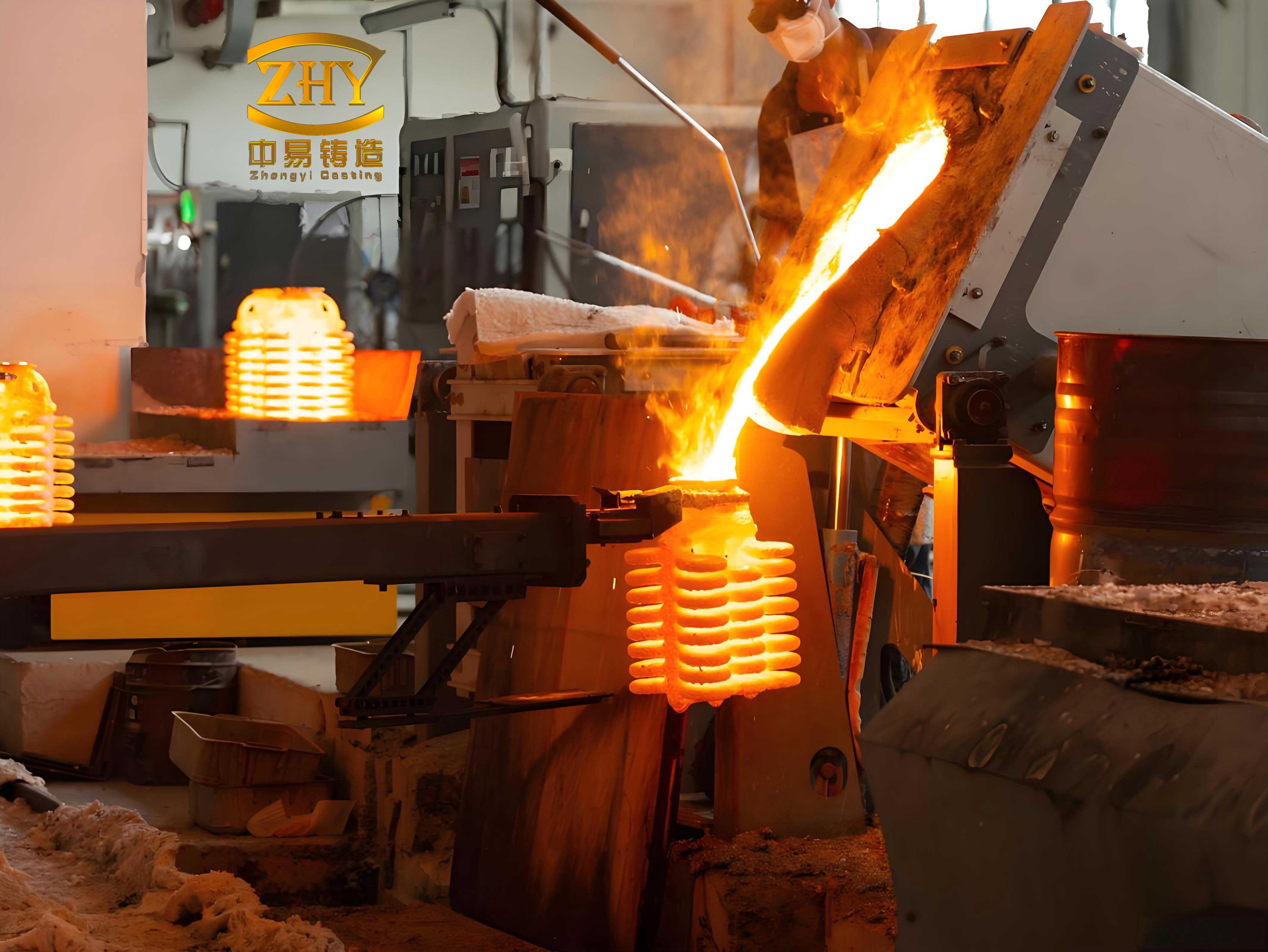
Investment casting offers a route to an integrated door body because it can form thin, complex walls in a ceramic shell and preserve a dense surface layer. The variant considered here combines investment casting with low-pressure filling: molten ZL114A aluminum alloy is pushed upward into a preheated shell under controlled gas pressure, held during solidification, and then released. This approach avoids the high injection speeds of high-pressure die casting and the large machine tonnage that accompanies it. It also avoids the weld seams and hemmed joints that add mass to a conventional stamped door.
From Stamped Assemblies to a Cast Door Body
A conventional door body is assembled from an outer panel, an inner panel, a window-frame assembly, an intrusion beam, hinge reinforcements, and lock reinforcements. Stamping is efficient for uniform-thickness panels, but it produces separate parts that must be joined by spot welding, structural adhesive, and hemming. Hem flanges and weld overlaps are material that contributes to mass but not directly to stiffness. Aluminum substitution makes the joining problem harder because aluminum is more reactive, and fusion welding can introduce oxide inclusions and porosity in thin panels. The integrated casting route removes the inner-to-outer panel hem, consolidates the reinforcement strategy, and replaces the separate intrusion beam with local ribs on the outer panel.
The cast door body studied here is made of ZL114A, a high-strength Al-Si casting alloy with good fluidity and low hot-cracking tendency. The component has a mass of 13.6 kg and an envelope of 408 × 345 × 1242 mm. The thinnest region is the inner panel at 1.5 mm, while the reinforcing ribs reach 3 mm. The ribs are placed where a conventional door would carry an intrusion beam and local reinforcements, so the casting performs the structural role of several stamped parts. The trade-off is that rib intersections become thermal nodes during solidification, and these nodes are the main locations where shrinkage porosity can form.
Structural Performance of the Casting-Oriented Geometry
The door body is a shell-type part, so a neutral-surface finite-element model is appropriate. HyperMesh was used for geometry cleanup, midsurface extraction, mesh repair, and thickness assignment. The final shell mesh contained 413,789 surface elements with a nominal element size of 6 mm. The model was exported to ANSYS with ZL114A properties: density 2.65 g/cm³, elastic modulus 69 GPa, and Poisson’s ratio 0.3. Small holes, fillets, and chamfers that do not affect global stiffness were removed before meshing; local features that control stiffness were retained.
Modal analysis gives a first natural frequency of 42.2 Hz for the free door body. Road-wheel excitation is typically in the 1–30 Hz range, road roughness in the 1–3 Hz range, and engine excitation in the 20–30 Hz range. A first mode above 30 Hz therefore keeps the door away from the main excitation bands. The first mode is a window-frame bending mode, followed by inner-panel breathing and combined window-frame/inner-panel modes at higher frequencies. The result does not prove NVH performance for the assembled vehicle, but it does show that the casting-oriented geometry is not intrinsically soft in the frequency range that matters for door shake.
Stiffness was checked under seven load cases: sinking with the door closed under its own weight, sinking with the door open and an 800 N load at the latch, upper and lower torsion under 900 N, window-frame corner and mid-span loads of 200 N, and inner/outer waistline loads of 100 N. The simulated maximum deformation and the corresponding stiffness values are summarized below. The criterion values are the design limits used for the door-body check.
| Load case | Maximum deformation (mm) | Stiffness (N/mm) | Criterion deformation (mm) | Criterion stiffness (N/mm) |
|---|---|---|---|---|
| Sinking, closed door and open-door 800 N case | 2.7 | 296.3 | 4.5 | 250.1 |
| Upper torsion, 900 N | 4.8 | 187.5 | 10 | 91.5 |
| Lower torsion, 900 N | 4.8 | 187.5 | 7 | 91.5 |
| Window-frame corner, 200 N | 3.8 | 65.8 | 5 | 50 |
| Window-frame mid-span, 200 N | 3.3 | 60.7 | 6 | 40 |
| Inner waistline, 100 N | 0.9 | 111.1 | 1.2 | 100 |
| Outer waistline, 100 N | 0.5 | 200.0 | 1.2 | 100 |
The stiffness margins are not uniform. Torsion and window-frame corner stiffness are the tightest cases, while the waistline panels have substantial margin. That pattern is consistent with a thin-wall shell whose global bending and torsion are controlled by the window-frame ring and the lower sill, not by the flat panel fields. The modal and stiffness results support the geometry as a feasible casting-oriented design, but they do not cover strength, crash intrusion, hinge fatigue, or seal-gap distortion under combined road loads.
Wax Pattern Injection and Tooling Design
In investment casting, the wax pattern carries the geometry and surface quality into the ceramic shell. Dimensional error in the wax pattern is therefore transferred to the casting. The pattern material is an F28-448 mid-temperature wax with a melt density of 1.06 g/cm³, a solid density of 1.12 g/cm³, a recommended melt temperature of 61–66 °C, a mold temperature of 25–35 °C, and a transition temperature of 55 °C. The parting surface is placed on the inner-panel side. Core heads for the central cavity pass through three openings in the inner panel, which helps locate the core and vent the cavity during injection. The vent holes are also used later for ceramic rods that stiffen the wax pattern during handling.
Gate location was screened with Moldflow using four layouts. The comparison used fill time, flow-front temperature difference, pressure at the velocity-to-pressure switch, volumetric shrinkage, and the number of visible weld lines. The results are summarized below.
| Gate scheme | Number of gates | Fill time (s) | Flow-front ΔT (°C) | Pressure at V/P switch (MPa) | Volumetric shrinkage (%) | Visible weld lines |
|---|---|---|---|---|---|---|
| 1 | 3 | 7.275 | 5.57 | 33.2 | 5.138 | 4 |
| 2 | 5 | 7.299 | 3.09 | 32.3 | 5.180 | 5 |
| 3 | 7 | 7.295 | 2.74 | 36.2 | 5.242 | 7 |
| 4 | 10 | 7.313 | 2.72 | 33.7 | 5.211 | 11 |
Scheme 1 has the lowest shrinkage and only four weld lines, but the individual weld lines are long and wide, which is unfavorable for a brittle wax pattern. Scheme 2 was selected because it combines a moderate gate count, the lowest pressure at the velocity-to-pressure switch, a flow-front temperature difference of 3.09 °C, and a balanced filling pattern. The five-gate layout uses point gates with a 2 mm diameter, a hot-runner system, a main runner 80 mm long with end radii of 12 mm and 16 mm, and branch runners with a 10 mm radius. The hot-runner choice keeps the wax from cooling in the long feed path before it reaches the cavity.
The cooling system uses water as the medium, with a channel diameter of 20 mm, a channel-to-mold distance of 50 mm, and a channel pitch of 200 mm. The initial layout left the central ribbed cavity hotter than the surrounding walls, with a maximum wax temperature difference of 25.5 °C. Adding baffles inside the core and increasing the number of inlet paths reduced the maximum difference to 23.71 °C. This is a modest improvement, but it targets the region where the wax pattern is most likely to warp during cooling.
Wax injection parameters were screened with single-factor simulation runs. Melt temperature was varied from 56 to 70 °C, mold temperature from 15 to 36 °C, injection time from 6 to 20 s, and holding pressure from 30% to 100% of filling pressure. The useful windows were 56–60 °C melt, 30–36 °C mold, 6–10 s injection, and 50–70% holding pressure. A four-factor, three-level orthogonal array was then used with melt temperature at 56/58/60 °C, mold temperature at 30/33/36 °C, injection time at 6/8/10 s, and holding pressure at 50/60/70% of filling pressure. Range analysis ranked the factors as melt temperature > mold temperature > holding pressure > injection time. The best combination was 56 °C melt, 33 °C mold, 8 s injection, and 60% holding pressure, giving a predicted volumetric shrinkage of 3.863%.
Low-Pressure Investment Casting Process Design
The casting route uses a silica-sol shell with a wall thickness of 6 mm. The shell preheat temperature was initially set to 420 °C, and the pouring temperature to 720 °C. ZL114A has a liquidus of about 613 °C and a solidus of about 557 °C, so 720 °C provides roughly 100 °C superheat. For a 1.5–3 mm wall, that superheat is needed to avoid cold shuts, but it also increases oxidation and feeding demand. The optimized preheat temperature from the later simulation matrix was 480 °C. The combined linear shrinkage allowance is 1%, covering wax shrinkage, shell expansion, and metal solidification contraction. The draft is 0°10′ on the outer surface and 0°15′ on the inner surface for draft heights above 100 mm. The dimensional tolerance for the largest size class is about 1.02 mm.
The gating system is an open system with a riser outlet : runner : ingate area ratio of 1 : 1.6 : 2.15. The total ingate area is 48 cm², the runner area is 31.3 cm², and the riser outlet area is 19.5 cm². The mold uses two cavities to improve productivity and to reduce shell distortion during handling. The calculated low-pressure cycle is summarized below; the values are rounded from the pressure and fill-time calculations.
| Stage | Time (s) | Pressure at stage end (kPa) |
|---|---|---|
| Riser rise | 8 | 22 |
| Mold filling | 9 | 50 |
| Pressurization | 5 | 100 |
| Holding | 600 | 100 |
| Release | 2 | 0 |
The holding stage dominates the cycle. A 600 s hold is long for a thin-wall aluminum part, but it is consistent with the need to keep the ingate molten long enough to feed the casting and to avoid backflow when pressure is released. The 2 s release then returns unsolidified metal in the sprue to the crucible. In practice, the holding time would need to be matched to the shell temperature and the actual solidification time of the thickest feeding path, not only to the thin wall.
Filling, Solidification, and Defect Control
The initial gating layout used two rows of gates: four at the bottom of the outer panel and four in the ribbed region. Filling simulation showed that metal entered the cavity from the lower gates before the gating system was fully filled, and the rising front from the bottom gates lagged behind the front from the upper gates. The resulting surface height difference produced splashing and unstable filling, which is unfavorable for oxide control. The revised layout increased the number and total cross-section of the bottom gates. The revised filling simulation completed in 12.7 s with a stable rising front, and the metal remained above the liquidus at the end of filling.
Solidification starts in the thin inner panel and at the edges of the installation openings. By 180 s, most of the inner panel has solidified. At 250 s, the lower ingate region and the ribbed outer panel are still mushy, and isolated pools remain in parts of the window frame. By 680 s, the casting is essentially solid, while the ingate remains molten. The isolated pools are the source of shrinkage porosity: they cannot draw feed metal through already solidified walls. After gating optimization, the predicted shrinkage-porosity volume was 14.68 cm³, concentrated at rib intersections and in parts of the window frame.
Single-factor casting simulations varied filling time from 10 to 18 s, pouring temperature from 660 to 740 °C, and shell preheat temperature from 390 to 510 °C. The lowest defect volumes in those one-dimensional sweeps were 13.92 cm³ at 14 s, 14.01 cm³ at 720 °C, and 14.23 cm³ at 480 °C. A three-factor, three-level orthogonal array then used pouring temperature at 710/720/730 °C, shell preheat at 450/480/510 °C, and filling time at 12/14/16 s.
| Run | Pouring temperature (°C) | Shell preheat (°C) | Filling time (s) | Shrinkage-porosity volume (cm³) |
|---|---|---|---|---|
| 1 | 710 | 450 | 12 | 14.62 |
| 2 | 710 | 480 | 14 | 14.32 |
| 3 | 710 | 510 | 16 | 14.56 |
| 4 | 720 | 450 | 14 | 13.92 |
| 5 | 720 | 480 | 16 | 12.34 |
| 6 | 720 | 510 | 12 | 12.87 |
| 7 | 730 | 450 | 16 | 14.21 |
| 8 | 730 | 480 | 12 | 14.01 |
| 9 | 730 | 510 | 14 | 13.99 |
Range analysis ranked the factors as pouring temperature > shell preheat > filling time. The best combination was 720 °C pouring, 480 °C shell preheat, and 16 s filling, with a defect volume of 12.34 cm³. The ranking is physically plausible: pouring temperature changes the superheat and the amount of liquid that must be fed, while shell preheat changes the cooling rate and the lifetime of the feeding path. Filling time matters mainly through its effect on front stability and on the temperature field at the end of fill.
The remaining 12.34 cm³ of porosity was still concentrated at rib intersections and window-frame hot spots. Adding risers would lower yield and leave marks on a thin cosmetic panel; external chills are difficult to locate on an investment shell. The selected alternative was localized forced cooling with liquid nitrogen. Liquid nitrogen has a low boiling point and a high volumetric heat capacity, and it evaporates without leaving a residue. Directed jets at the shell surface near the hot spots increase the local solidification rate, break up the isolated pools, and promote directional feeding from the ingate. With this local cooling, the predicted shrinkage-porosity volume fell to 4.9 cm³, about 60% below the 12.34 cm³ obtained by parameter optimization alone.
Process Capability and Validation Gaps
The numerical results support a coherent process route: a casting-oriented door geometry with adequate modal and stiffness behavior, a wax pattern with a five-gate injection layout and a 3.863% volumetric shrinkage prediction, a low-pressure filling schedule of 22/50/100 kPa with a 600 s hold, and a final shrinkage-porosity volume of 4.9 cm³ after localized liquid-nitrogen cooling. The strongest quantitative case is the defect reduction: 14.68 cm³ after gating optimization, 12.34 cm³ after parameter optimization, and 4.9 cm³ after targeted cooling. The weakest part of the case is validation. These are simulation results, not measured castings.
The structural work covers modal and stiffness cases only. It does not cover yield strength, hinge fatigue, latch pull-out, crash intrusion, or the effect of casting porosity on local ductility. The wax pattern study uses one parting surface and four gate layouts; other parting surfaces, gate positions, and cooling-channel arrangements could change the weld-line pattern and the shrinkage field. The casting model predicts shrinkage porosity but does not resolve gas entrapment, oxide films, grain structure, or heat-treatment response. A production qualification would need physical trials with shell permeability, wax injection rheology, dimensional inspection, X-ray or CT porosity mapping, and mechanical testing of cast coupons.
The engineering value of the route is nevertheless clear. It replaces a multi-part stamped and welded assembly with a single thin-wall investment casting, uses low-pressure filling to avoid the turbulence of high-pressure die casting, and treats the thermal nodes of the casting as a tooling problem rather than a post-processing problem. The next step is not another global parameter sweep; it is local validation of the hot-spot cooling, the shell preheat uniformity, and the fatigue behavior of the cast door body under realistic hinge and latch loads.