
Screen plates are the coarse-crushing elements of roller-type coal crushers in thermal power plants. Large coal is struck and sheared between the rotating plates and the crushing drum before being conveyed to the next reduction stage. The plates therefore experience impact, compression, and shear, and the central mounting bore must remain clean enough for subsequent machining. A casting route that leaves porosity, sand holes, or slag near the bore creates scrap not only because of the defect itself but because it interrupts the machining sequence.
Water-glass-bonded CO2-cured sand casting was the established route for these plates. In production, a four-cavity flask yielded four plates, and about four of every twenty castings were scrapped after porosity and sand holes were exposed during dressing or rough machining, for an acceptance rate near 80%.
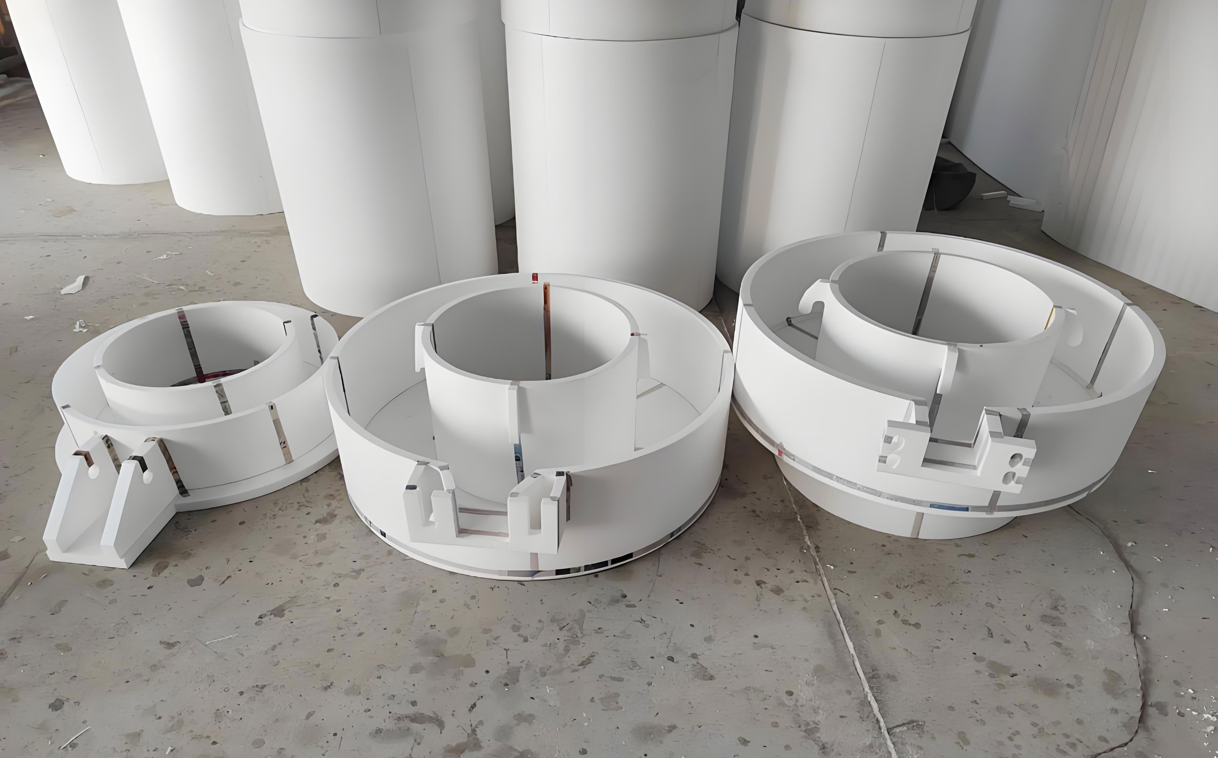
Lost foam casting replaces the bonded sand mold with an expendable polystyrene pattern embedded in unbonded dry sand. During pouring, the metal degrades the pattern; the decomposition products escape through a refractory coating and the sand, assisted by vacuum. The pattern carries the external shape and the central bore, so the mold has no parting line and no separate core for the bore. The quality window depends on foam density, coating, sand compaction, gating, pouring rate, and vacuum.
Pattern and coating control
Patterns were cut from polystyrene foam with a resistance wire. The effective density window was 0.016–0.018 g/cm3. Lower density gave weak patterns that could distort or collapse during compaction; higher density increased carbon pickup, gas porosity, inclusions, and incomplete filling. The pattern surface had to be smooth, with fused beads and no voids or inclusions. A 1.02% shrinkage allowance was applied. Sections were joined with white latex adhesive and dried for 24–48 h before coating and molding; residual moisture otherwise generated steam during pouring and could cause backfire or porosity.
The coating was a water-based quartz powder slurry. The quartz filler had a density of 2.65 g/cm3 and a thermal conductivity of 1.8 W/(m·K); water was the carrier, cellulose the suspending agent, and white latex the binder. The slurry was mixed in a ball mill for 4–6 h. Coated patterns were dried in an infrared oven at 52 ± 3 °C. The coating had to strengthen the pattern during handling and compaction and prevent metal penetration and sand holes without blocking gas escape.
Gating and molding: the bore is the critical feature
The first production design used vertical pouring. Inner gates 45 mm × 45 mm were placed on the teeth, and 50 mm × 50 mm runners fed from both sides of the sprue; six plates were cast per flask. The bore was severely burned on and could not be machined. The cause was insufficient dry-sand compaction inside the bore, which allowed metal to penetrate the sand.
The design was changed to horizontal pouring with a riser above the bore, keeping 45 mm × 45 mm inner gates on the teeth and 50 mm × 50 mm runners. An open gating system and a bottom-suction vacuum flask were used, again with six plates per flask. Molding was done in two vibration stages: 100–200 mm of bottom sand was placed and vibrated level; the pattern cluster was checked for exposed foam, sealed with refractory clay, and covered to half height; dry sand was hand-filled under the screen plate; a second vibration was applied while sand was added; and the sand under the plate was tamped with a wooden stick to prevent a void. The horizontal design eliminated bore burn-on and kept the bore machinable.
Melt, pour, and vacuum
The steel was melted in a 250 kg medium-frequency induction furnace. The charge was calculated for the specified screen composition, melted rapidly, and pushed down to avoid bridging; the composition was adjusted and the melt deoxidized. Tapping temperature was 1590–1610 °C. The ladle was held for 3–5 min, and pouring began when a surface film formed.
The pour rate had to match the rate at which the foam decomposed and the products were removed. If pouring was too slow, the metal front fell behind pattern loss, the gap widened, and the mold could collapse. If pouring was too fast, decomposition products could not escape, causing backfire, and turbulence could entrain gas and slag. The sprue and pouring cup were kept full, and metal was left in the cup at the end of the pour.
Vacuum was maintained during pouring at −0.06 to −0.04 MPa. After filling, it was reduced to −0.04 to −0.03 MPa for 15–20 min before the pump was shut off. The casting was held in the flask for 6 h and then air-cooled.
Heat treatment and hardness
The plates were quenched and tempered to meet the service requirement. Surface hardness after treatment was HBS 243–269, measured with a KPE300 Brinell hardness tester, within the user’s specification. This hardness is a shop acceptance measure; it confirms the heat-treatment response but does not by itself establish wear life.
Defect comparison and production performance
The values in Table 1 are average defect counts per casting for production batches, not single-casting readings. They allow the sand-cast route and two lost foam casting variants to be compared on the same basis.
| Process route | Gas porosity (defects per piece) | Sand holes (defects per piece) | Slag inclusions (defects per piece) | Burn-on |
|---|---|---|---|---|
| Water-glass CO2 sand casting | 3.2 | 2.8 | 3.1 | None |
| Lost foam casting, vertical pouring | 1.3 | 1.2 | 1.0 | Yes, in the bore |
| Lost foam casting, horizontal pouring | 0.3 | 0.2 | 0.1 | None |
The horizontal lost foam route reduced gas porosity from 3.2 to 0.3 per piece, sand holes from 2.8 to 0.2, and slag inclusions from 3.1 to 0.1 compared with water-glass CO2 sand casting. Vertical pouring lowered internal defects to 1.3, 1.2, and 1.0 per piece, respectively, but produced bore burn-on and was not acceptable. Horizontal pouring produced no burn-on. Ultrasonic testing found no distinct internal defects in the horizontal lost foam castings, and the castings reached quality grade 3.
Production data also showed a change in flask output. The sand-cast route produced four plates per flask; the lost foam route produced six, so direct flask productivity was 1.5 times higher. The sand-cast acceptance rate was about 80%, with four scrapped castings in a 20-piece lot, while the horizontal lost foam lot reached 100% acceptance, a ratio of 1.25. The 100% figure is a trial-lot result, not a guarantee for every future lot.
Production implications
The benefit of lost foam castings for this part came from the complete process package, not from the name of the process. Vertical pouring was already better than sand casting internally, but the bore could not be machined. Changing to horizontal pouring and adding a bore riser addressed sand compaction and feeding, which were the actual causes of scrap.
Lost foam also simplifies the mold: there is no water-glass mixing, no CO2 curing, and no separate bore core; the dry sand is unbonded and the pattern is expendable. The trade-off is that pattern density, joining, drying, coating, and compaction become critical. The process moves the quality burden upstream to pattern and coating control.
The comparison is a production comparison rather than a controlled experiment; the improvement combines pattern quality, horizontal gating, a bore riser, and vacuum practice. For this screen plate, that combination produced a sound, machinable bore and a high acceptance rate. The result should not be read as a universal lost foam yield, because the same defects can reappear if foam density, coating permeability, sand compaction, or pour rate move outside the window. Within that window, lost foam casting is a practical route for wear-resistant crusher screen plates that require a clean central bore and a low scrap rate.