
As mentioned above, the open gating system is not conducive to slag retaining at the initial stage of pouring, and it is easy to produce secondary oxidation slag inclusion. The closed gating system has good slag resistance, but the pressure at the inner gate is high, easy to spray and splash, resulting in a large amount of secondary oxidation slag inclusion. Because the flow rate of molten metal at the minimum section of the closed gating system ν It can not be controlled at will, but depends on the metal hydraulic head HP and flow coefficient μ, It can be calculated by the following formula.
discharge coefficient μ The value mainly depends on the resistance of molten metal in the gating system and mold during mold filling, and the flow coefficient of cast iron μ The flow coefficient of cast steel is 0.35-0.60 μ Values are 0.25-0.50. If take μ= 0.40, then HP = 80mm, and the flow rate of molten metal will reach 0.5m/s. Therefore, in actual production, especially the gating system of large castings, it is difficult to meet the requirement that the mold filling speed is less than 0.5m/s. The flow velocity of molten metal at the minimum section of gating system of some important castings is counted. The maximum flow velocity of molten metal in the gating system of some castings is less than 0.5 m / s, but the filling flow velocity of a considerable number of castings is higher than 0.5 m / s, even about 1.0 m / s, which is obviously an unavoidable problem.
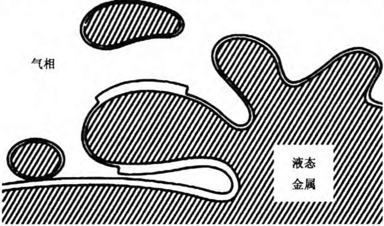
In order to achieve good slag retaining capacity of the gating system, closed or semi closed gating system shall be adopted, i.e. ∑ f straight > ∑ f transverse > ∑ f inner or Σ f straight < ∑ f transverse > ∑ f inner and Σ f straight > ∑ f inner. The minimum section of the closed or semi closed gating system is located in the ingate, that is, the ingate with the highest flow rate. If the ingate is not designed properly, spraying and splashing are easy to occur in the process of liquid metal filling, resulting in a large amount of secondary oxidation slag inclusion. Fig. 1 is a schematic diagram of oxidation slag inclusion formed when disturbance occurs during metal liquid filling.
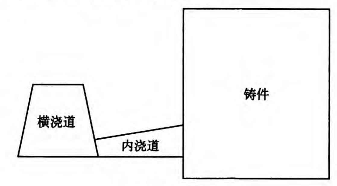
For large castings, when the flow rate at the minimum section exceeds 0.5m/s, only the measures to reduce the pressure of the liquid metal at the outlet of the inner sprue can be taken to reduce the flow rate of the liquid metal, make the liquid metal flow smoothly into the mold cavity, and prevent the disturbance and spray phenomenon during the filling process of the liquid metal. Fig. 2 is a schematic diagram of the depressurized ingate. The minimum section of the gating system is set at the junction of the runner and the ingate. The ingate gradually expands from the junction of the runner to the junction of the cavity, so as to reduce the liquid metal pressure and mold filling speed, and avoid the spray and splash of liquid metal. The reduced pressure sprue can effectively reduce the generation of secondary oxidation slag and iron beans. Zong Zhenhua and others adopt a semi closed gating system, and the ratio of each component is f straight: F resistance: ∑ f inner = 1:0.7:2.24. During the pouring process, the liquid metal can quickly fill the straight gate to avoid the involvement of gas. The area of the liquid metal after passing through the blocking section is expanded, and the liquid metal can more stably fill the inner gate and mold. The author has adopted the inner gate decompression gating system in a large number of sand casting products, such as automobile nodular cast iron supercharger shell, railway vehicle nodular cast iron axle box, aluminum alloy gearbox and other important parts, and achieved good results.