
For example, the liquid filling state of the casting at different times is represented. The red represents the molten metal liquid. According to the temperature range on the left, the temperature of the metal liquid can be roughly judged according to the color, and the gray area is a foam appearance. It can be seen from the diagram that the gating system has been filled with molten metal for a longer time and a slower filling type at 5.2s. This is because the runner is filled with foam patterns, causing resistance to the flow of molten metal. At the same time, the foam pattern is exposed to molten high temperature molten metal to decompose and vaporate away the heat of the molten metal and reduce the temperature of the molten metal. Thus, the flow performance of liquid metal becomes slow and the filling time of liquid metal is increased; The mold filling of the whole casting was completed at 21.79s.
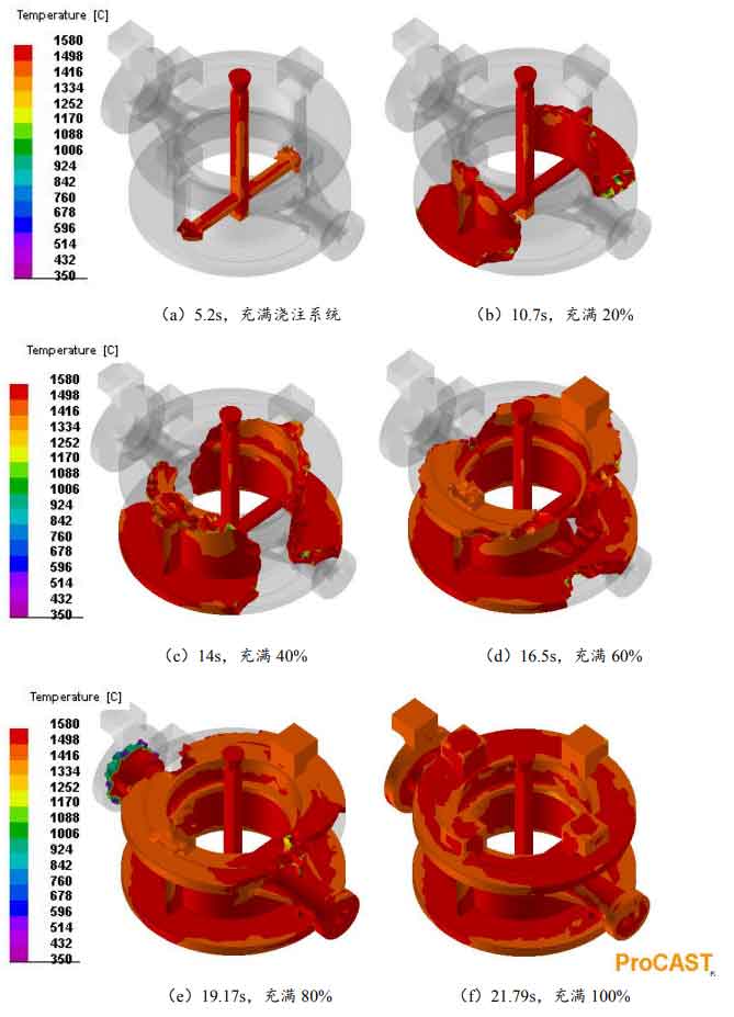
As can be seen from the figure, from figure a to figure F, the time interval required for each 20% filling is 5.5s, 3.3s, 2.5s, 2.67 and 2.62 respectively. It is known that the time interval of metal liquid filled with 20% cavity varies little. This indicates that the flow of molten metal from the straight runner to the runner to the bottom of the casting is uniform and slow, and there is no serious spatter phenomenon from the bottom up to the whole casting. The gas generated by the combustion of the foam pattern can be discharged well during the filling process of the lost foam casting. Slag inclusion can also float well to the riser.