
In my extensive experience within the foundry industry, the pursuit of efficient, high-quality, and cost-effective manufacturing methods for complex components is a constant endeavor. One particularly challenging area involves the production of thin-wall castings using gray iron, a material prized for its good machinability, damping capacity, and cost-effectiveness but notorious for its relatively poor fluidity compared to ductile iron. This inherent characteristic makes it susceptible to defects like cold shuts, mistruns, and chilling in sections with minimal thickness. Traditional green sand molding, while versatile, often struggles to consistently meet the stringent dimensional accuracy and surface finish requirements for such parts, especially in high-volume production scenarios. It was within this context that my team and I turned our focus to the Sand-Faced Permanent Mold (SFPM) casting process, also known as iron mold with sand lining. This report details our first-hand application, adaptation, and optimization of this process specifically for the batch production of intricate thin-wall gray iron castings.
The core principle of the SFPM process involves using a reusable metal mold (the “iron mold” or “permanent mold”) whose cavity is lined with a thin, cured resin-coated sand layer. This combines the benefits of permanent mold casting—excellent dimensional stability, rapid cooling, and smooth surface finish—with the flexibility and refractoriness of a sand mold. For gray iron casting, this hybrid approach is critical. The metal mold provides rapid heat extraction, promoting a dense microstructure, but if uncontrolled, it can lead to excessive chilling and white iron formation in thin sections. The insulating sand layer interposed between the molten metal and the metal mold allows for modulation of the cooling rate. Our project centered on a specific component analogous to a sanding machine base: a thin-walled, box-like structure with uniform walls around 6 mm, local minima down to 2.3 mm, and demanding requirements for non-machined surface finish, sharp corners, and tight dimensional tolerances (conforming to CT8 per GB6414-86). The order volume was substantial, demanding a monthly output in the tens of thousands, which made the productivity and consistency of SFPM highly attractive.
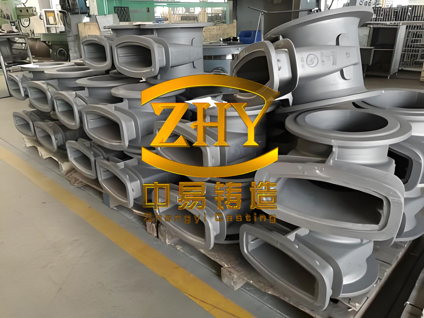
The journey began with a thorough analysis of the challenges. Translating the part geometry into a robust SFPM process design presented several hurdles. First, the part’s trapezoidal shell structure dictated a specific molding orientation, necessitating that the entire cavity be formed in one mold half (either the cope or the drag). This eliminated the possibility of a parting line at the center to reduce pattern draw depth. Consequently, the hardened sand shell’s adhesion to the pattern plate during stripping became a significant concern. Second, and most critically for gray iron casting, were the metallurgical and thermal challenges. The combination of thin sections (especially around windows and edges), the inherently lower fluidity of gray iron, and the high thermal conductivity of the mold assembly created a perfect storm for filling-related defects. The rapid chilling at the metal front could easily cause cold shuts before the mold was completely filled. Furthermore, the risk of carbide formation (chill) at these thin sections was high. Third, the internal core, which was part of the metal mold assembly, could mechanically restrain the shrinkage of the solidifying gray iron casting, creating high thermal stresses and predisposing the component to cold cracking.
To systematically address these issues, we developed a multi-faceted工艺设计 strategy. The philosophy was to leverage the adjustable parameters of the SFPM process—sand layer thickness, metal mold thickness, gating design, and thermal management—to create a favorable environment for filling and solidification of thin-wall gray iron casting.
Gating System and Filling Dynamics
The primary objective was to achieve rapid, uniform, and tranquil filling to beat the rapid heat loss. We opted for a pressurized (choke-at-the-ingate) gating system but with carefully moderated ratios to minimize turbulence. The system was designed as a semi-pressurized type with the relationship: $$F_{sprue} : F_{runner} : F_{ingate} = 1.2 : 1.5 : 1$$. Here, \(F\) represents the cross-sectional area. This ratio ensures a slight pressurization in the runner, helping to push metal into the ingates but not so severe as to cause excessive velocity and jetting. The number of ingates was increased to distribute the metal entry points, ensuring shorter flow paths to the extremities of the cavity. The ingates were positioned to promote directional solidification towards appropriate feeding areas. The fill time was targeted to be under 7 seconds. The governing fluid flow considerations can be related using a simplified Bernoulli-based approximation for metal head pressure and the need to overcome friction in thin sections: $$\Delta P = \rho g h – \frac{128 \mu L Q}{\pi D^4}$$ where \(\Delta P\) is the effective pressure driving flow, \(\rho\) is the molten gray iron density, \(h\) is the effective sprue height, \(\mu\) is the apparent viscosity, \(L\) and \(D\) are the characteristic length and hydraulic diameter of thin sections, and \(Q\) is the volumetric flow rate. This highlights that for thin sections (small \(D\)), the pressure loss due to viscous friction becomes enormously sensitive, necessitating higher \(\Delta P\) via larger gating or higher metal head.
| Parameter | Design Value / Target | Rationale |
|---|---|---|
| Gating Ratio (Sprue:Runner:Ingate) | 1.2 : 1.5 : 1 | Controlled pressurization for fast fill with minimal turbulence. |
| Number of Ingates | Increased from baseline design | To reduce flow length and fill time for each stream. |
| Target Pouring Temperature | > 1320°C | Compensates for fluidity loss and rapid cooling in thin-wall gray iron casting. |
| Target Fill Time | ~7 seconds | Prevents metal front freezing before mold complete fill. |
| Pouring Cup/Sprue Base Design | Well/Strainer core used | To reduce splash and vortex, ensuring a smoother entry. |
Ventilation and Sand Layer Design
Venting in SFPM is twofold: venting the sand mold during its formation via the shooting process, and venting the cavity during metal pouring. Inadequate venting during sand shooting can lead to soft spots or poor compaction, especially in areas far from the shoot head. During pouring, the displaced air must escape quickly; otherwise, back-pressure can impede filling or cause blows. We incorporated strategic vents in the metal mold, leading from the cavity extremities to the exterior. The permeability of the cured sand layer itself also plays a role. A balance is needed: sufficient permeability to allow air escape but fine enough to produce a smooth surface. We selected a finer grain sand than typical for thicker castings. This served a dual purpose: it reduced the surface roughness of the mold cavity, thereby decreasing the frictional resistance to molten metal flow—a critical factor for thin-wall gray iron casting—and it enhanced the as-cast surface finish of the part. The sand grain distribution was tightly controlled.
The thermal design of the mold assembly is the heart of成功 for thin-wall gray iron casting in SFPM. The goal is to slow the initial cooling rate just enough to allow complete fill and avoid chill, but still maintain a cooling rate higher than sand casting to achieve the desired mechanical properties. This is managed by the thickness of the sand lining (\(t_s\)) and the metal mold (\(t_m\)). We treat this as a composite wall problem. The instantaneous heat flux (\(q\)) from the solidifying metal can be approximated by: $$q = \frac{T_{metal} – T_{ambient}}{\frac{1}{h_i} + \frac{t_s}{k_s} + \frac{t_m}{k_m} + \frac{1}{h_o}}$$ where \(h_i\) and \(h_o\) are the interfacial and ambient heat transfer coefficients, and \(k_s\) and \(k_m\) are the thermal conductivities of the sand and metal mold, respectively. For gray iron casting in thin sections, we want to increase the dominant thermal resistance in the early stages. Since \(k_m >> k_s\), the sand layer thickness \(t_s\) is the most effective variable. Therefore, we increased the sand layer thickness, particularly on the internal cores (which are surrounded by hot metal), to values between 8-20 mm, while the external sand layer was 5-12 mm. Concurrently, the metal mold thickness was minimized to just maintain structural rigidity and thermal mass for temperature stability over cycles, typically between 15-25 mm. This combination increases the thermal resistance, reducing the initial chilling severity, and also improves the mold’s yield to accommodate the shrinkage of the gray iron casting, mitigating hot tearing and cold cracking risks.
| Component | Parameter Range | Primary Function |
|---|---|---|
| Resin-Coated Sand Layer Thickness (Cavity side) | 5 – 12 mm | Insulation, surface finish, and contraction allowance. |
| Resin-Coated Sand Layer Thickness (Core side) | 8 – 20 mm | Enhanced insulation to delay solidification on the core, reduce shrinkage stress. |
| Metal Mold (Iron Type) Thickness | 15 – 25 mm | Provides structural support and thermal mass for cycle stability. |
| Sand Grain Fineness Number (GFN) | Higher than standard (e.g., ~70-85) | Improves mold surface smoothness to aid fluidity in thin-wall gray iron casting. |
| Mold Preheat Temperature | ~180 – 220°C | Reduces thermal shock, improves sand layer adhesion, and moderates initial cooling rate. |
Pattern Design and Production Layout
To meet the high-volume requirement efficiently, we designed the pattern for one mold to produce two castings (one-cavity per part, two cavities per mold). This doubled the productivity per molding cycle. The pattern had to accommodate the deep draw from the trapezoidal shape. We applied generous draft angles (where permissible by part design) and employed high-quality, polished pattern plates. A critical step was the application of release agents. We used a combination of a sprayed-on liquid parting agent for general coverage and a more viscous, brush-applied mold release paste or wax on severe undercuts and deep sections. This significantly reduced the stripping force required to separate the cured sand shell from the pattern. The stripping sequence was timed precisely: the mold was opened soon after the sand was cured enough to handle but before it reached its ultimate strength, which can make it brittle. The sand shell then continued its final curing ex-situ. This “early strip” practice was vital for preserving mold integrity and achieving a high pattern release success rate.
Foundry Floor Operations and Process Control
The theoretical design must be executed with precision on the shop floor. Our operational protocol emphasized consistency in several key areas. First, the application of release agent was standardized and frequently audited. Second, the melting and pouring practice was tightened. We maintained the pouring temperature for gray iron casting at a minimum of 1320°C, often between 1320-1350°C, to provide a sufficient superheat margin. The ladles were preheated to prevent temperature drop during transfer. Pouring was conducted swiftly and steadily to achieve the target fill time. Third, mold temperature cycling was managed. While “hot mold” pouring is beneficial, an excessively hot mold (>250°C) could degrade the sand binder. We aimed for a steady-state mold operating temperature through controlled cycle times. Fourth, and crucially for preventing cracking, the knockout time was optimized. Allowing the gray iron casting to cool too long in the restrictive metal mold increases stress. We found that opening the mold and extracting the casting within 5 to 10 minutes after pouring was optimal. At this point, the casting had developed enough strength to handle but was still hot enough to have some ductility to relieve residual stresses without cracking. The casting was then placed on an insulated conveyor for slow, stress-relieving cooling.
The entire production line was compact, fitting within a 200 m² area. It comprised a continuous mixer for resin-coated sand, the shooting and curing station for mold production, a conveyor system for transferring prepared molds to the pouring line, the pouring station, a cooling conveyor, and a knockout/cleaning station. The closed-loop nature of the process minimized sand waste and environmental dust compared to traditional green sand systems.
Results and Performance Metrics
The implementation of this tailored SFPM process was highly successful in mass-producing the thin-wall gray iron casting. The production rate consistently exceeded 40 castings per hour, comfortably meeting the monthly demand of over ten thousand pieces. The quality outcomes were particularly gratifying. The surface finish of the castings was excellent, with sharp, well-defined corners and edges on features like the 45° chamfers. The dimensional accuracy consistently met the CT8 specification, with wall thickness variation held within ±0.5 mm. The internal soundness was confirmed through random destructive testing and visual inspection of broken samples; no cold shuts or mistruns were found in the production batches. The fear of chill in the 2.3 mm sections was alleviated by the insulating sand layer; microstructure analysis revealed a fully pearlitic matrix with type A graphite, free of carbides at the edges, confirming the effectiveness of the thermal moderation for this gray iron casting.
From an economic and resource efficiency standpoint, the benefits were substantial. The process yield (casting weight divided by total metal poured) reached 89%, a significant improvement over typical sand casting yields for such parts, which often linger around 60-70%. The scrap rate was maintained below 2%. A remarkable metric was the iron-to-sand ratio, which was approximately 1:1 by weight. In traditional sand casting, this ratio can be 1:5 or even higher, meaning for every ton of gray iron casting produced, 5 tons of sand might be processed and potentially discarded. The SFPM process, with its reusable metal mold and thin, cured sand shell, dramatically reduces sand consumption and waste. Furthermore, the improved dimensional accuracy led to a direct reduction in casting weight from a nominal 9 kg to a finalized 7.02 kg, achieving significant material savings without compromising functionality. This weight reduction, compounded over tens of thousands of parts, translates into major cost savings in raw iron and reduced energy for melting.
| Performance Indicator | SFPM Process (Achieved) | Typical Green Sand Casting (Benchmark) |
|---|---|---|
| Process Yield (Metal Yield) | ~89% | ~65-75% |
| Dimensional Consistency (Wall Thickness) | Within ±0.5 mm | Typically ±0.8 – ±1.2 mm |
| Surface Finish (Ra estimate) | 6.3 – 12.5 μm | 12.5 – 25 μm |
| Scrap Rate (for filling/chill defects) | < 2% | 5% – 10% (for similar complexity) |
| Iron-to-Sand Consumption Ratio (by weight) | ~1:1 | ~1:5 to 1:10 |
| Production Floor Space Density | High (Line in <200 m²) | Lower (Requires larger sand system & storage) |
Mathematical Modeling and Future Optimization
While our initial success was based on empirical design and iteration, we recognize the power of simulation for future projects. The solidification of thin-wall gray iron casting in an SFPM mold can be modeled using the heat conduction equation with appropriate boundary conditions. The governing equation in three dimensions is: $$\rho c_p \frac{\partial T}{\partial t} = \nabla \cdot (k \nabla T) + \dot{Q}_{latent}$$ where \(\rho\) is density, \(c_p\) is specific heat, \(k\) is thermal conductivity, \(T\) is temperature, \(t\) is time, and \(\dot{Q}_{latent}\) is the latent heat release rate due to the liquid-solid phase change of gray iron. The boundary condition at the casting-mold interface is complex, involving a gap formation as the gray iron casting shrinks away from the sand layer. A simplified approach uses an effective heat transfer coefficient \(h_{interface}\) that varies with time and temperature. Optimizing the process involves solving this system to predict thermal gradients, solidification fronts, and potential defect sites. For instance, the criterion for avoiding a cold shut can be related to the fluidity length (\(L_f\)) of the iron, which is a function of composition and cooling rate, and the actual flow length (\(L_a\)) in the mold: $$L_a < L_f = f(C.E., T_{pour}, \dot{T}_{cooling})$$ where \(C.E.\) is the carbon equivalent of the gray iron. Our process design effectively increased \(L_f\) by moderating \(\dot{T}_{cooling}\) (via sand layer) and raising \(T_{pour}\), ensuring \(L_a < L_f\) was always true.
Further optimization could involve dynamic control. One could envision a process where the sand layer thickness is varied intelligently across the mold cavity—thicker in extreme thin sections and areas prone to cracking, and thinner in heavier sections that need faster cooling. The gating design could also be optimized using computational fluid dynamics (CFD) simulations to visualize metal flow and temperature distribution during filling of the thin-wall gray iron casting, minimizing oxide formation and turbulence.
Conclusion and Broader Implications
In conclusion, our hands-on experience has conclusively demonstrated that the Sand-Faced Permanent Mold casting process is not only viable but highly advantageous for the high-volume production of complex, thin-wall gray iron castings. The keys to success lie in a holistic design approach that acknowledges the unique challenges of gray iron fluidity and shrinkage. By strategically manipulating the gating for fast fill, the sand layer for thermal moderation and surface quality, and the metal mold for structural integrity, we created a stable and productive process. The operational discipline in pouring temperature, mold release, and controlled knockout further cemented the quality outcomes. The results—high dimensional accuracy, excellent surface finish, low scrap rates, and remarkable material/energy efficiency—present a compelling case for adopting SFPM for similar applications. This project underscores that for demanding thin-wall gray iron casting components destined for batch production, moving beyond conventional sand casting to a controlled, hybrid process like SFPM can yield significant competitive advantages in quality, cost, and manufacturing footprint. The principles and parameters detailed here provide a foundational framework that can be adapted and refined for other challenging geometries in gray iron casting, paving the way for more widespread and innovative use of this efficient casting technology.