
The pursuit of lightweight, high-performance materials in modern engineering has consistently directed attention towards magnesium alloys. The intrinsic properties of magnesium—low density, high specific strength and stiffness, excellent dimensional stability, superior thermal conductivity, and exceptional damping capacity—make it an outstanding candidate for critical applications across the aerospace, defense, and automotive sectors. Furthermore, its excellent machinability and recyclability enhance its appeal for sustainable manufacturing. However, the widespread adoption of cast magnesium components, or sand casting parts, is often hampered by significant processing challenges. The hexagonal close-packed (HCP) crystal structure of magnesium inherently limits its ductility and formability at room temperature. More critically for casting, magnesium exhibits high chemical reactivity, particularly a strong affinity for oxygen, and suffers from relatively poor fluidity and a pronounced tendency to form shrinkage defects during solidification. These characteristics make the production of sound, complex, and thin-walled sand casting parts exceptionally difficult. This article details a comprehensive investigation into the sand casting process for a specific complex thin-walled magnesium alloy component, systematically analyzing and comparing different gating and feeding strategies to establish a robust and practical manufacturing protocol.
Sand casting, as a foundational and versatile manufacturing process, involves creating a mold from a sand aggregate. The success of producing high-integrity sand casting parts, especially from challenging alloys like magnesium, hinges on the meticulous design of every subsystem: the mold and core sands, the gating system, and the feeding mechanism. For the subject component—a cylindrical vessel with an average wall thickness of 4 mm, a minimum thickness of 3 mm, a length of 600 mm, and a major diameter of 480 mm—these design choices become paramount. The technical requirements mandated high dimensional accuracy on the outer surface, internal soundness with a uniform and dense microstructure, and the absolute absence of defects such as sand inclusions, gas porosity, shrinkage cavities, shrinkage porosity, and hot tears.
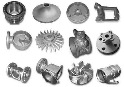
The foundational process design adopted a three-part flask (cope, drag, and cheek) and a single, large core to form the internal cavity of the cylinder. The core was fabricated using a synthetic oil sand mixture, while the mold itself employed a specialized synthetic sand designed for magnesium. This mold sand typically contains inhibitors like sulfur compounds, boric acid, and halides to suppress the violent reaction between molten magnesium and moisture in the sand. Both molds and cores were thoroughly dried in resistance ovens to eliminate any residual moisture, a critical step to prevent hydrogen gas porosity, a common defect in magnesium sand casting parts. To ensure smooth, turbulent-free filling of the mold cavity—a necessity for thin sections—a bottom-gating system with a choke at the base (closed) transitioning to larger areas upstream (open) was employed. However, the central challenge remained counteracting magnesium’s poor feeding characteristics during solidification.
The solidification of metals is governed by thermal gradients and the evolution of latent heat. For a cylindrical, thin-walled casting, the solidification time can be approximated using Chvorinov’s rule:
$$ t = B \left( \frac{V}{A} \right)^n $$
where \( t \) is the total solidification time, \( V \) is the volume of the casting, \( A \) is its surface area, \( n \) is an exponent (often ~2), and \( B \) is the mold constant. For thin-walled geometries, the \( V/A \) ratio is small, leading to rapid solidification. While this can refine the microstructure, it severely restricts the time available for liquid metal to flow and feed the shrinkage that occurs during the phase change from liquid to solid. The volumetric shrinkage \( \varepsilon_v \) for magnesium alloys can be significant:
$$ \varepsilon_v = \frac{\rho_s – \rho_l}{\rho_l} \times 100\% $$
where \( \rho_l \) and \( \rho_s \) are the density of the liquid and solid phases, respectively. Without effective feeding, this shrinkage manifests as macro-porosity (shrinkage cavities) or micro-porosity (shrinkage scatter). Traditional risers (or feeders) alone are often insufficient for extended thin walls because the long, narrow feeding paths freeze off before the riser can supply liquid metal.
To address this fundamental issue, a vertical slot feeder (also known as a knife gate or slot gate) system was integrated. This system is not merely a channel for metal entry but acts as a thermally active, supplementary feeder. It consists of a thick vertical section attached to the casting wall. Its thermal mass remains liquid longer than the thin casting wall, creating a directional solidification sequence from the casting into the feeder. The efficiency of this feeding can be related to the pressure head \( P \) available to drive liquid metal through the partially solidified dendrite network, often described simplistically by Darcy’s law for flow in a porous medium:
$$ \frac{dP}{dx} = – \frac{\mu}{K} v $$
where \( \mu \) is the dynamic viscosity, \( K \) is the permeability of the mushy zone, and \( v \) is the superficial velocity. The slot feeder maintains a higher thermal gradient at the casting-feeder interface, sustaining permeability \( K \) in the critical region for a longer duration and thereby enhancing feeding.
Our initial process (Process A) positioned this vertical slot feeder system on the inside of the cylindrical wall. The molten metal would enter from the bottom via a downsprue, flow through runners and ingates into the interior volume of the core, and then fill the casting cavity from the inside out, with the internal slot feeder and top risers intended to provide feeding. The modified process (Process B) relocated the vertical slot feeder system to the outside of the cylindrical wall. The gating remained a bottom-fed system, but the feeding pathway was now from the exterior. Additionally, external chill plates (cooling fins) were placed at identified thermal hot spots (like intersections and thicker sections) on the exterior mold to promote faster, more directional solidification.
The comparative analysis of these two configurations reveals critical insights into the physics of producing such sand casting parts. The following table summarizes the core advantages and disadvantages of each approach from a process engineering standpoint.
| Aspect | Process A: Internal Slot Feeder | Process B: External Slot Feeder with Chills |
|---|---|---|
| Core Manufacturing | Complex. Requires precise integration of the feeder into the core body, increasing core fragility and making de-coreing difficult. | Simpler. The core is a standard cylindrical shape. The feeder is part of the mold cavity, separate from the core. |
| Metal Flow & Filling | Direct impingement of metal stream onto the internal feeder/casting interface can cause turbulence and oxide film entrainment. | Smoother, more controlled filling from the bottom outward. The external feeder acts as a flow-off for initial cold metal and dross. |
| Heat Transfer & Solidification | Primary heat extraction is radially outward. The internal feeder’s effectiveness is limited by the insulating effect of the core. | Primary heat extraction is radially outward, aided by external chills. The external feeder is in direct contact with the mold sand, enabling more effective heat transfer, creating a stronger thermal gradient from the casting wall into the feeder. |
| Feeding Path & Efficiency | The feeding path is through the thickness of the casting wall into the internal feeder. This path is short but narrow, prone to premature freezing. | The feeding path is laterally along the wall from the external feeder. The slot feeder’s large cross-section maintains a longer liquid life, feeding a greater length of the wall effectively. |
| Casting Clean-up | Extremely difficult. Removing the internal feeder from the complex inner surface risks damaging the casting. | Straightforward. External feeders and chills are easily removed by standard cutting and grinding operations. |
The theoretical advantages of Process B were validated through rigorous practical experimentation. Three castings were produced using each of the two process configurations. After standard post-casting operations—shakeout, thermal treatment (T4 or T6, as per alloy specification), and rough machining—the castings underwent non-destructive and destructive evaluation. Full-volume X-ray radiography was performed to detect internal defects like shrinkage and gas porosity. Furthermore, test coupons were sectioned from critical locations on the castings for metallographic examination and mechanical testing (tensile and hardness) to assess microstructural uniformity and integrity. The results are consolidated in the table below.
| Process | Casting ID | X-Ray Radiography Results | Metallographic & Mechanical Analysis |
|---|---|---|---|
| A (Internal Feeder) | 1 | Multiple surface cracks on outer wall. Significant shrinkage cavities and gas porosity visible on inner wall. | Microstructure not uniform; porous regions present. Mechanical properties inconsistent and below specification. |
| 2 | Shrinkage and gas porosity largely eliminated. Sand inclusions present on outer surface. | Microstructure generally sound but shows local variations in grain size and secondary phase distribution. Mechanical properties non-uniform. | |
| 3 | Gas holes, shrinkage cavities, and sand inclusions absent. Minor shrinkage porosity at identified hot spots. | Microstructure sound. Mechanical properties meet minimum spec but show some scatter across locations. | |
| B (External Feeder) | 1 | No shrinkage, gas holes, or cracks detected. Minor sand wash on exterior surface. | Microstructure acceptably dense and uniform. Mechanical properties consistent and meet specification. |
| 2 | Completely free from shrinkage, porosity, cracks, and sand inclusions. | Microstructure exceptionally fine and uniform. Mechanical properties exceed specification and show high consistency. | |
| 3 | Effectively free from all major casting defects. | Microstructure sound and uniform. Mechanical properties meet specification consistently. |
The data demonstrates a clear and decisive superiority for Process B. The external vertical slot feeder system, synergized with strategic chilling, fundamentally alters the solidification dynamics to favor the production of high-quality sand casting parts. The thermal management can be modeled more formally. Consider Fourier’s law of heat conduction applied at the casting-mold interface:
$$ q = -k \frac{dT}{dx} $$
where \( q \) is the heat flux, \( k \) is the thermal conductivity of the mold material, and \( dT/dx \) is the temperature gradient. The external sand mold and the chill plates provide a high-conductivity path, maximizing \( q \) and creating a steep thermal gradient (\( dT/dx \)) directed from the casting center towards the mold wall and feeder. This strong directional solidification is essential for feeding. The effectiveness of the slot feeder is a function of its modulus (volume-to-surface-area ratio), which must be greater than that of the casting section it is intended to feed:
$$ M_{feeder} > M_{casting} $$
where \( M = V/A \). For an external longitudinal feeder attached to a plate-like wall, its design ensures this condition, allowing it to remain liquid and “pump” metal into the solidifying casting to compensate for shrinkage over an extended length. The application of chills at hot spots further modifies the local solidification time, ensuring that these regions, which would normally be the last to freeze and become isolated from the feeder, are instead solidified in a controlled sequence towards the feeder.
In contrast, the internal feeder in Process A suffered from several thermodynamic handicaps. The core material, typically with lower thermal conductivity than the mold sand, acts as an insulator. This reduces the heat extraction rate from the inner surface of the casting, flattening the thermal gradient and potentially creating an inverse gradient where the center of the wall (near the hot core) stays liquid longer than the area near the mold. This can lead to centerline shrinkage or porosity. Furthermore, the mechanical difficulty of creating and removing a complex core-integrated feeder introduced variability and damage, negatively impacting the final quality of the sand casting parts.
The transition to the optimized external feeder process (Process B) resulted in a dramatic reduction in the scrap rate. Where Process A consistently yielded a scrap rate exceeding 18%, primarily due to shrinkage and cleaning-related damage, Process B enabled a sustained scrap rate of less than 5% in production. This represents not only a significant cost saving but also a reliable method for manufacturing complex, thin-walled magnesium components that meet stringent quality standards.
In conclusion, the successful sand casting of complex thin-walled magnesium alloy components is an exercise in precise thermal and hydraulic management. This investigation underscores that traditional gating and feeding approaches are inadequate for such geometries. The strategic implementation of an external vertical slot feeder system, combined with a bottom-gated filling system and targeted use of chill plates, creates the necessary conditions for directional solidification and effective feeding. This methodology directly counters the inherent limitations of magnesium—its poor fluidity and high shrinkage—by providing a dedicated, thermally efficient liquid metal reservoir that remains active throughout the critical solidification period. The resultant process has proven to be robust, practical, and scalable for the batch production of high-integrity magnesium alloy sand casting parts, successfully eliminating major defects and ensuring consistent microstructural and mechanical properties. This framework provides a validated technical blueprint for expanding the application envelope of sand-cast magnesium alloys into more demanding structural roles.