
Automobile lightweight is one of the important measures to achieve energy conservation and emission reduction The development of new technologies for automotive engines, in addition to the use of all aluminum alloy in mechanical aspects In addition to lightweight materials such as cylinder blocks and cylinder heads, more and more engines are being manufactured at zero In terms of component structure and function, an integrated and integrated structural design is adopted . At present, the latest technology in the industry is cylinder head integrated exhaust manifold technology, which The technology eliminates traditional exhaust manifold components and integrates the exhaust manifold into the cylinder
The exhaust side of the cover uses the high-temperature gas discharged to heat the coolant
The cooling system of a car adds heat sources The internal cooling channel of traditional aluminum alloy cylinder heads is usually composed of a water channel sand The core can be formed, and the internal cooling structure of the integrated cylinder head becomes very complex Miscellaneous, usually formed by 2-3 water channel sand cores, resulting in a change in the overall structure of the water channel sand cores It is very thin and has uneven wall thickness, making it easier to produce castings compared to traditional cylinder heads Create defects. Currently, there are issues related to shrinkage, porosity, and slag inclusion in aluminum alloy cylinder heads There are many research reports on defects [8-16], but there are concerns about casting blockage caused by sand core fracture There are few reports on the issue of death. Therefore, this study focuses on the aluminum alloy integrated cylinder head
A detailed analysis was conducted on the problem of blocked water channels in castings, including process parameters and pouring We have made on-site adjustments and verifications in terms of process and core making process, and have utilized Simulation software is used for simulation, and through scheme optimization and actual production verification, the Finally, the casting defect problem was completely resolved, providing an analysis of the casting defect problem Provide reference for resolution.
1 Product structure and defect description
The structure of an integrated aluminum alloy cylinder head is shown in Figure 1, with its overall outline dimensions 419.85mm × 314.12mm × 143.58mm, mass 13.92 Kg, the average wall thickness of the casting is 8.22mm, and the maximum wall thickness is 34.47mm, The minimum wall thickness is 3.85mm. Casting cover edge (i.e. oil chamber sand core and two metals) The theoretical design between the side molds generally has a wall thickness of 4mm. Exhaust manifold set The cross-sectional structure of the area is shown in Figure 1c, with the upper and lower waterways The relationship between sand cores, upper and lower exhaust duct sand cores, oil chamber sand cores, and metal bottom molds
In terms of design, the general wall thickness is 4mm, and the minimum local position is 3.85mm.
During the appearance inspection of the cylinder head castings produced using the initial process, it was found that the cylinder There is abnormal blockage in the inner cavity of the cover channel, and all castings were dissected (see Figure)。
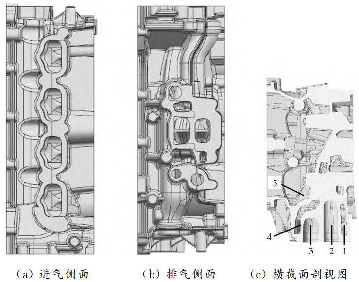
Fig.1 Structure Diagramofaluminuntegratedcylinder cover
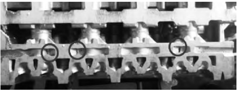
Figure 2 BlockageInSideWaterJackTofCylinderCove Product
2 Analysis of the causes of casting defects
2.1 Defect physical object and sand core structure
The defect status of the casting is shown in Figure 3. Through dissection of the casting, it was found that all The fleshy state of the blocked position shows a spreading trend, which can be basically determined as blocked The main reason for the formation of plugs is that the sand core of the upper water channel comes out during the casting forming process Cracks present. As the filling process progresses, the aluminum liquid drills into the crack location and expands The expansion ultimately leads to the formation of excess flesh, which leads to the blockage of the casting waterway. Statistical analysis was conducted on the location of faults and defects, and it was found that the main defect locations were
Concentrate in a relatively fixed area, as shown in Figure 4, marking the defect at position 3 in the figure
The proportion is relatively the highest, and by analyzing the sand core structure, it can be clearly seen that the fault。
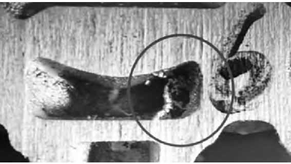
Figure 3 Diagram casting defect
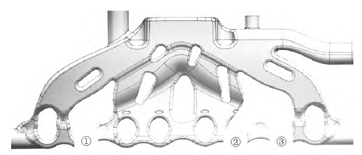
Fig.4 Schematic diagram ofsandcoreoffupperwater jacketandlocation ofblocking defect
2.2 On site process adjustment and verification
2.2.1 Casting process analysis
By analyzing the defects, it is preliminarily believed that the aluminum liquid has filled the mold in the casting The impact force on the sand core during the process exceeds its strength, causing the sand core to fracture, This in turn leads to the generation of beryllium, leading to the blockage of the casting water channel. To reduce aluminum liquid during mold filling The impact force on the sand core during the process will be determined by the gravity casting pouring time on site Extending from 18s to 24s and conducting pouring verification, it was found that the appearance of the casting was formed
Good, but defects still exist after dissection. Due to the fact that the sand core absorbs a large amount of heat during the casting filling process, sand An increase in core temperature will lead to a decrease in its strength, and the pouring temperature of the aluminum liquid will be adjusted from The temperature dropped from 700 ℃ to 680 ℃, resulting in a cold lap on the appearance of the casting. Continue to
The pouring temperature was adjusted to 690 ℃, and it was found that the appearance of the casting was well formed, But the defects still exist after dissection. The adjustment plan based on on-site process parameters is invalid, which affects the casting process The material direction is adjusted from the position of the exhaust side cover edge to the position of the intake side cover edge, The comparison diagram before and after adjustment is shown in Figure 5. By adjusting the feeding direction
Avoiding or reducing the frontal impact of aluminum liquid on the fault area of the sand core in the upper water channel Strike, but the plan still failed after on-site verification.

Fig.5 Comparisonofcastingsbeforeandafterfeeding directionadjustment
2.2.2 Analysis of Core Making Process
Improving the strength of sand cores can reduce the risk of sand core fracture, but excessively high sand cores Strength may make residual sand in the inner cavity of the casting less prone to collapse, affecting the cleanliness of the casting Degrees. To verify the effectiveness of this scheme, the resin content of the coated sand was adjusted The tensile strength of the sand core in the upper water channel was increased from 1.6 MPa to 2.6 MPa for pouring verification, and the results showed that defects still exist after the casting was dissected. Quenching coatings use chemical reactions to change the coagulation within the coating layer range Adjust the solidification sequence of castings by adjusting the solidification conditions and cooling rate. On At the same time as the strength of the sand core in the water channel is improved, on-site monitoring of the corresponding water channel defects Brushing and applying chilling coating on the surface area of the sand core for pouring verification, and the results are as follows:
The defect still exists after dissection.

Fig.6 Simulationresultsofsand-shootingprocessofsandcoresinupperwaterjacket
2.3 Numerical simulation analysis
2.3.1 Sand shooting process simulation
Simulate the sand shooting process using FLOW-3DCAST simulation software, and set the simulation boundary conditions according to the actual process parameters on the production site. The simulation results of the sand shooting process of the upper channel sand core are shown in Figure 6. It can be seen that the filling process at the defect is good, without obvious shrinkage and air entrainment, indicating that the sand blasting process is relatively reasonable.
2.3.2 Casting process simulation
Using FLOW-3DCAST software to analyze the casting forming process
Simulation, due to the complex structure of the 3D model, a tetrahedral structure is used to
Perform finite element mesh generation. Simulation of Casting Temperature Field and Upper Channel Sand Core Temperature Field during Mold Filling Process The results are shown in Figure 7. It can be seen that as the filling process progresses, when the aluminum liquid is filled When forming the sand core area of the upper waterway, the temperature of the sand core in the upper waterway will rapidly increase. The temperature distribution diagram of the sand core in the upper water channel during the completion of casting filling is shown in Figure 8. Yes It can be seen that the color at the thin connection position of the sand core structure is very deep and too concentrated. By comparison, it was found that the local temperature of the sand core was too high (as shown in Figure 8) Distribution of coil labeling and casting fault location (see coil labeling in Figure 4)The pattern is basically consistent. The internal temperature of the sand core at the location with the highest proportion of faulty defects The solid phase rate of surface aluminum liquid was analyzed, and the results are shown in Figure 9. It can be seen that casting
The instantaneous temperature at the center of the sand core during the completion of mold filling is 465 ℃,The solid state rate of aluminum liquid on the surface of the sand core is 6.89%. Enter after the casting filling is completed During the solidification process, as the solidification process progresses, the sand core will continue to absorb heat and remain warm The degree will continue to rise.

Fig.7 Temperaturefieldsimulationresultsofcastingsandsandcoreinupperwaterjacketduringfillingprocess
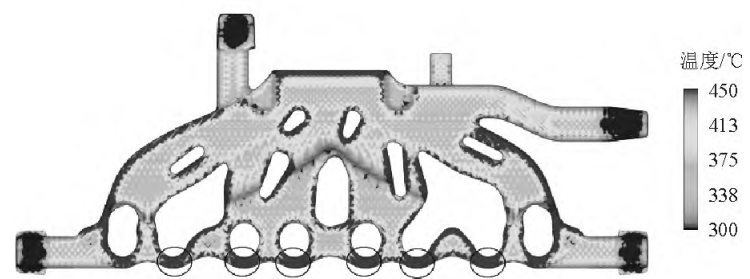
Fig.8 Temperature distribution of sandcore in overwater jacket after completing casting filling

Fig.9 Simulationresultsofinternaltemperatureofsandcoreandsolidfractionofsurfacemoltenaluminum
3 Plan improvement and validation
After identifying the root cause of the blockage defect in the casting water channel through the aforementioned analysis, the sand core structure of the upper water channel was designed and optimized, and the three thin connection positions of the sand core were thickened, as shown in Figure 10. Optimization of local position of sand core The cross-sectional areas before and after optimization are 160.98 and 240.87 mm2, respectively. The comparison of the cross-sectional areas before and after the optimization of the local position of the sand core is shown in Figure 10b.
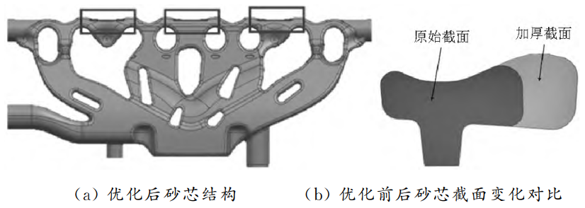
Fig.10 Schematicdiagramofsandcoreinupperwater jacketbeforeandafteroptimization
Re simulate the optimized solution, and the results are shown in Figure 11. can It can be seen that the temperature at several thin connections of the sand core in the optimized upper channel is too high
The phenomenon has been significantly improved, and the center position of the sand core inside the casting is at the completion of mold filling The instantaneous temperature is 357 ℃, a decrease of 108 ℃ compared to before optimization. From temperature From the curvature of the change curve, it can be seen that after optimization, it becomes smoother compared to before, indicating that the temperature at local positions of the sand core has been effectively transmitted after optimization The phenomenon of excessive concentration of local internal stress in the sand core has also been improved. Implement validation of the above optimization plan. After continuous production of 30 castings After dissection, no blockage defects were found in the casting water channel, and the optimized production was carried out
The anatomical results of the sand core and casting are shown in Figure 12. After mass production and tracking, the The problem did not occur again, and the blockage defect of the casting water channel was completely resolved.
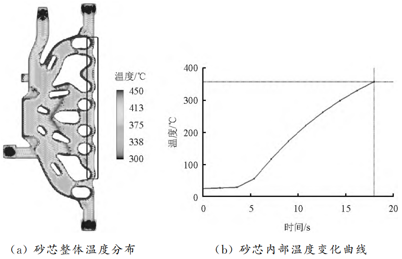
Figure 11 Simulation Results of Temperature Field of Sand Core in Upstream Waterway after Optimization
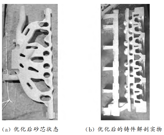
Figure 12 Anatomical Results of Sand Core and Casting Produced after Optimization
4 Conclusion
(1) Compared to traditional cylinder heads, the aluminum alloy integrated cylinder head has a non
Often complex, the internal cooling channels of the cylinder head are composed of 2 or 3 independent water channels The sand core is cast and formed, and the sand core structure becomes very thin and uneven in wall thickness, Compared to traditional cylinder heads, they are more prone to casting defects.
(2) The simulation of sand blasting process can be used to divide the sand core forming and filling process Analyze and identify the risk points of shrinkage and porosity during sand core forming, and confirm the design of the mold exhaust structure Reasonableness of the sand core and ensuring the sand by increasing its density or compactness Core quality.
(3) Regarding casting defects, from on-site process parameters, pouring process, and manufacturing
Multiple aspects such as core technology have been adjusted and verified on site, but none have been achieved Improved efficiency, and later simulated using simulation software to identify casting defects
The root cause of the birth, and through scheme optimization and actual production verification, ultimately Solved the casting defect issue.