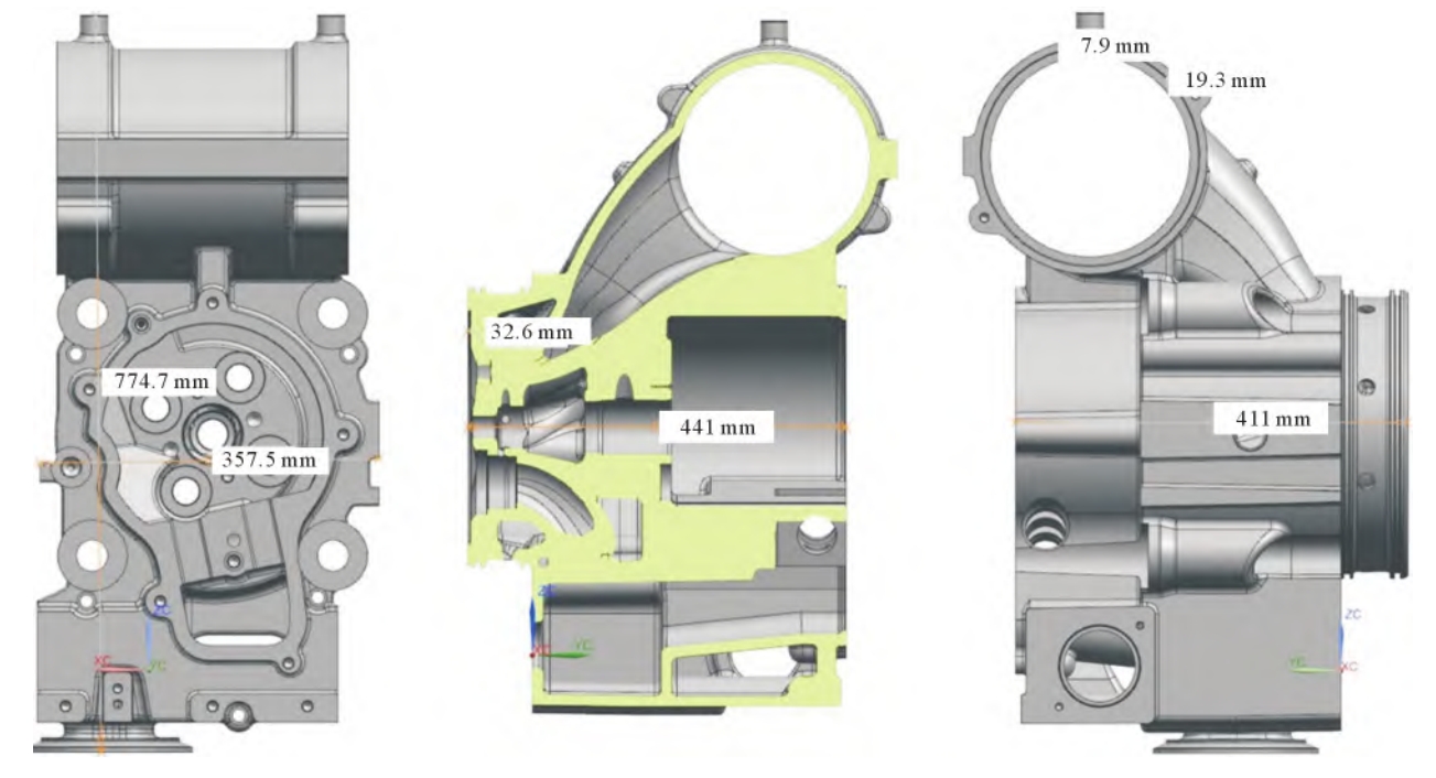
Maximum: 30 mm (combustion surface), Minimum: 8 mm (intake and exhaust ducts)
Structure Complexity
High, with complex internal and external structures including intake and exhaust ducts, upper and lower water channels, through screw holes, injectors, and exhaust pipes
1.2 Casting Process
Casting Process Details
Description
Molding Method
All molds are made of gray iron and produced by a core shooter. The sand core is phenolic resin to ensure strength and dimensional accuracy
Molding Style
Upper and lower molds, with the combustion surface facing down
Pouring Method
Bottom pouring, with two pieces in one box
2. Existing Problems and Cause Analysis
2.1 Shrinkage Defects in Thin – Walled Areas
Problem
Details
Defect Appearance
Shrinkage defects in the intake and exhaust holes after machining
Impact on Cylinder Head
Reduces the ability to withstand high temperature and pressure, shortens the service life, and may even cause product scrapping
Causes
1. Graphite expansion in the later stage of solidification of nodular iron casting may not offset the volume shrinkage in the early stage, requiring a reasonable cold iron and riser process. 2. Unstable alloy composition, such as high or low carbon equivalent and excessive Mg element, may also lead to shrinkage defects. However, it is determined that the main cause in this case is insufficient feeding
2.2 Slag Inclusion on the Spring Seat Surface
Problem
Details
Defect Appearance
Slag inclusion on the spring seat surface after machining
Impact on Cylinder Head
Affects the ability to withstand spring pressure and may lead to material failure over time
Causes
The bottom pouring process causes slag to float up. When the casting solidifies, the slag floats to the surface. Since the spring seat surface is at the top of the casting in this process, if the slag does not fully float to the machining allowance position, defects will occur after machining
3. Defect Solution
3.1 Solution for Shrinkage Defects in Thin – Walled Areas
Solution
Details
Original Cold Iron Scheme Problem
The original cold iron scheme in the intake and exhaust holes had only 4 small cold irons. During pouring and solidification, the iron liquid near the cold iron solidified first, creating a local hot spot. The area away from the cold iron cooled slowly, and due to the thin – walled self – feeding ability being insufficient, shrinkage defects occurred
Improvement Measures
Increase the volume of the cold iron and evenly cover all surfaces of the intake and exhaust cylinders to ensure simultaneous cooling and solidification, thereby eliminating the local isolated hot spot and shrinkage defects
3.2 Solution for Slag Inclusion on the Spring Seat Surface
Solution
Details
Improvement Method
Increase the machining allowance by 5 mm on the original basis
Effect
The slag in the iron liquid can fully float up, eliminating the slag inclusion on the spring seat surface
4. Conclusion
Conclusion
Details
Shrinkage Defect Solution
For the shrinkage defects in the thin – walled areas of complex nodular iron castings, covering the cold iron comprehensively can effectively eliminate the hot spots and then the shrinkage defects
Slag Inclusion Solution
For the slag inclusion defect of the cylinder head, increasing the machining allowance of the casting can make the defect fully float to the surface of the casting, ultimately achieving the purpose of defect elimination
The production process and quality improvement of the cylinder head of a certain marine diesel engine are of great significance. Through the analysis and solution of shrinkage defects and slag inclusion problems, the casting process of the cylinder head has been effectively optimized, improving the quality and qualification rate of the cylinder head. This provides a reference for the production of similar nodular iron castings and helps to improve the overall performance and safety of marine diesel engines.