1. Introduction
Marine diesel engines play a crucial role in the operation of ships, and the quality of their cylinder heads directly impacts the overall performance and safety of the engine. The cylinder head is also one of the components that experience the harshest service conditions in the engine, as it needs to withstand alternating high and low temperatures and pulsating high and low pressures during operation. Therefore, extremely high quality requirements are imposed on cylinder head parts.
Ductile iron is widely used in the manufacturing of high-power medium and high-speed diesel engine cylinders due to its excellent strength, toughness, wear resistance, and impact resistance. However, ductile iron has a tendency to form shrinkage porosity and shrinkage cavities during solidification, and most of the research on shrinkage problems in ductile iron castings has focused on thick and large parts, with relatively little attention paid to thin-walled castings. Therefore, in the casting process design of cylinder heads, the rational design of the gating system, risers, and venting system is crucial to ensure the quality of the castings. This article analyzes the causes of shrinkage porosity defects in the intake and exhaust ports and slag inclusion problems on the spring seat surface of a certain type of cylinder head during the casting process, and proposes corresponding solutions.
2. Cylinder Head Structure and Casting Process
2.1 Cylinder Head Structure
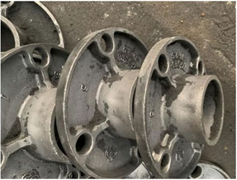
Figure 1 shows a certain type of cylinder head, which is made of QT400 – 15 with the chemical composition shown in Table 1. The overall dimensions of the cylinder head are 775 mm × 358 mm × 411 mm, and the weight of the rough casting is 168 kg. The wall thickness of the cylinder head varies significantly, with the maximum wall thickness of 30 mm on the combustion surface and the minimum wall thickness of 8 mm in the intake and exhaust ports. The internal and external structures of the cylinder head are complex, and the cavity is composed of intake and exhaust ports, upper and lower water channels, through screw holes, fuel injectors, exhaust pipes, etc., which increases the manufacturing difficulty.
2.2 Casting Process
Due to the complex structural dimensions of the cylinder head that cannot be met by traditional manual core-making methods, all molds are made of gray iron and produced using a core shooter. The sand cores are made of phenolic resin to ensure the strength and dimensional accuracy of the cores. The casting is assembled in an upper and lower mold with the combustion surface facing downwards, with two pieces in one box. The pouring method is bottom pouring, as shown in Figure 2.
3. Existing Problems and Cause Analysis
Most casting defects are internal and only become visible after machining. After machining, this cylinder head exhibited shrinkage porosity defects in the intake and exhaust ports and slag inclusion problems on the spring seat surface, resulting in a qualification rate of less than 50%.
3.1 Thin-Walled Shrinkage Porosity Defects
Analysis revealed that this defect was shrinkage porosity. In previous production, machining of the cylinder head revealed defects in the intake and exhaust ports (Figure 3), accounting for 60% of all defects. During diesel engine operation, the intake and exhaust ports need to withstand high temperatures and pressures as they are responsible for inhaling and expelling high-temperature gases. When defects occur in the pipe holes, the ability of the cylinder head to withstand high-temperature and pressure loads is reduced, shortening its service life. Severe defects can even render the product unusable.
There are two main reasons for the shrinkage porosity defects in the cylinder head: ① Ductile iron solidifies in a mushy manner. During the early stage of solidification, volume shrinkage occurs first, followed by graphite expansion in the later stage. This graphite expansion is more pronounced in thick and large parts. Casting process design usually takes advantage of this characteristic of ductile iron to fully utilize the self-feeding ability of the casting and achieve qualified casting quality and cost reduction. However, if the graphite expansion in the later stage cannot compensate for the volume shrinkage in the early stage of solidification, shrinkage porosity defects may occur, which requires a reasonable cold iron and riser process. ② Unstable alloy composition of the material can also lead to shrinkage porosity defects in the casting. In ductile iron, an excessively high or low carbon equivalent (CE) and excessive Mg content in the molten iron can increase the occurrence of shrinkage porosity defects.
Regarding the shrinkage porosity caused by unstable alloy composition, since our company has a strict operating process during melting and pouring, with furnace-front testing using a carbon-sulfur analyzer, and no similar defects have occurred in other ductile iron castings of the same material, it can be concluded that the shrinkage porosity in the intake and exhaust ports of the cylinder head is due to insufficient feeding. Subsequent process improvements will be targeted at this aspect to eliminate the defects.
3.2 Slag Inclusion on the Spring Seat Surface
Slag inclusion on the spring seat surface after machining is also one of the main reasons for the unqualified cylinder head, as shown in Figure 4. Since the spring seat surface of the cylinder head needs to withstand the constantly changing pressure of the spring, relatively strict technical requirements are imposed on this area. Even a small defect can cause material failure after long-term reciprocating impact. Therefore, slag inclusion on the spring seat surface is also a problem that needs to be addressed.
By comparing other cylinder heads of different models with the same process, it was found that slag inclusion on the spring seat surface also occurred. Therefore, it can be concluded that the defect on the spring seat surface is due to the unreasonable pouring process in this area. Bottom pouring causes the slag in the molten iron to float upwards. When the casting solidifies, the slag floats to the surface of the casting and is finally removed by machining. The combustion surface of the cylinder head is the part that directly faces the combustion chamber during service. Therefore, in the casting process of the cylinder head, the quality of the combustion surface must be ensured first to meet its service requirements. Hence, the cylinder head is usually cast with the combustion surface facing down using the bottom pouring method. As can be seen from the cylinder head part drawing, this pouring method causes the spring seat surface of the cylinder head to be located at the top of the casting, and the slag floats to the spring seat surface. If the slag cannot completely float to the machining allowance position, defects will form on the spring seat surface after machining.
4. Defect Solution
4.1 Solution for Thin-Walled Shrinkage Porosity Defects
As shown in Figure 5a, the original cold iron scheme for the intake and exhaust ports only placed 4 cold irons. Although this can cause the casting to solidify quickly, preventing shrinkage porosity and shrinkage cavities caused by solidification shrinkage, due to the relatively large size of the intake and exhaust ports of the cylinder head and the relatively small size of the cold irons, during pouring and solidification, the molten iron at and near the cold irons solidifies first, while the molten iron far from the cold irons is less affected by the chilling effect of the cold irons, forming a local hot spot. The cooling rate in this area is relatively slow, and at the same time, the self-feeding ability of the thin-walled part is insufficient, ultimately leading to the occurrence of shrinkage porosity defects. The subsequent improvement scheme is to eliminate the local isolated hot spot.
For the isolated hot spot in ductile iron, the following improvements can be made: ① Set risers and vents at the hot spot to achieve the feeding effect and eliminate shrinkage porosity defects; ② Change the cold iron process to eliminate the hot spot and prevent the occurrence of process-induced isolated hot spots. Regarding the elimination of the hot spot by adding risers and vents, since the cylinder head sand cores are all made using a core shooter, if risers and vents are added, the sand core machine mold needs to be changed, resulting in complex operation processes and high costs. Therefore, the defect is eliminated by changing the cold iron process. The original cold iron size is relatively small and cannot effectively chill all the intake and exhaust ports. Therefore, by increasing the volume of the cold iron and evenly covering all surfaces of the intake and exhaust ports as shown in Figure 5b, all surfaces are affected by the same cold iron, ultimately achieving simultaneous cooling and solidification and eliminating the defect.
4.2 Solution for Slag Inclusion on the Spring Seat Surface
For slag inclusion on the spring seat surface, the defect is eliminated by increasing the machining allowance. As shown in Figure 6b, an additional 5 mm allowance is added on the basis of the original machining allowance, allowing the slag in the molten iron to float sufficiently and ultimately eliminating slag inclusion on the spring seat surface.
Using the new process, 130 cylinder heads were produced again. After machining, as shown in Figure 7, no shrinkage porosity defects were found in the intake and exhaust ports, and the defects on the spring seat surface also disappeared completely. The qualification rate reached 93%, an increase of 40%.
5. Conclusion
For the thin-walled shrinkage porosity defects of complex ductile iron castings, they can be effectively eliminated by fully covering the cold iron to eliminate the hot spot. The slag inclusion defect of the cylinder head can be eliminated by increasing the machining allowance of the casting, allowing the defect to float sufficiently to the surface of the casting.
6. Acknowledgments
The authors would like to express their gratitude to all those who have provided assistance and support in the research and writing of this article. Special thanks go to the colleagues in the company for their cooperation and valuable suggestions in the process of analyzing and solving the casting defects of the cylinder head. Without their efforts, this research could not have been successfully completed.