
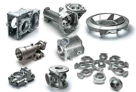
In modern heavy industry, particularly in sectors like railway transportation, the demand for high-integrity, complex components is paramount. The manufacturing of critical parts such as locomotive diesel engine bearing housings, axle housing boxes, and support brackets relies heavily on casting technology. My research focuses on the formability and defect analysis of box-type steel castings—a category of sand casting parts characterized by intricate geometries, varying wall thicknesses, and high structural load requirements. The quality of these castings directly influences the performance, safety, and longevity of the final assembly. This work details a comprehensive study employing numerical simulation to understand, predict, and mitigate defects in such components, fundamentally shifting the paradigm from trial-and-error based process design to a science-driven, simulation-validated approach.
1. Introduction and Significance of Casting Simulation
The casting of sand casting parts, especially large steel components, presents significant challenges. Defects like shrinkage cavities, porosity, hot tears, and cold shuts can originate from complex interactions between the molten metal’s fluid flow, heat transfer, solidification patterns, and stress development. Traditional process design relies heavily on empirical knowledge, leading to prolonged development cycles, high scrap rates, and elevated costs. The advent of casting process numerical simulation has revolutionized this field. It allows for the virtual prototyping of the entire casting process—filling, solidification, and cooling—enabling the prediction of potential defects before any metal is poured.
The core significance of this technology lies in its ability to visualize and quantify physical fields that are impossible to observe in real-time during production. By solving the governing equations for fluid dynamics and heat transfer, simulation software can output the temperature field, velocity field, and fraction solid during solidification. Based on these results and established defect prediction criteria, engineers can identify probable defect locations, sizes, and formation mechanisms. This capability enables the optimization of critical process parameters such as gating and riser design, chilling application, and pouring temperature, thereby ensuring casting quality, shortening lead times, and reducing production costs. For box-type sand casting parts with their inherent thermal and geometrical complexities, numerical simulation is not just beneficial but essential for achieving reliable and economical production.
2. Overview of Casting Numerical Simulation Technology
The development of casting simulation has evolved through distinct phases, from basic temperature field calculations in the 1960s to today’s sophisticated multi-physics, multi-scale modeling. Modern commercial software packages can handle coupled analyses of filling, solidification, stress, and even microstructure evolution for various casting processes, including sand casting.
The general workflow of a casting simulation system comprises three main modules:
- Pre-processing: This involves creating the 3D CAD model of the part, molds, cores, gating, and risering system. The model is then discretized into a finite number of elements (meshing). The quality and resolution of this mesh critically impact the accuracy and computational cost of the simulation.
- Numerical Computation (Solver): This is the core engine where the physical equations are solved. Key models include:
- Fluid Flow (Filling): Solved using Navier-Stokes equations, often with volume-of-fluid (VOF) methods to track the liquid metal front.
$$ \frac{\partial \rho}{\partial t} + \nabla \cdot (\rho \vec{v}) = 0 $$
$$ \frac{\partial (\rho \vec{v})}{\partial t} + \nabla \cdot (\rho \vec{v} \vec{v}) = -\nabla p + \nabla \cdot \vec{\tau} + \rho \vec{g} $$ - Heat Transfer & Solidification: Solved using the energy conservation equation, incorporating latent heat release.
$$ \rho C_p \frac{\partial T}{\partial t} = \nabla \cdot (k \nabla T) + \rho L \frac{\partial f_s}{\partial t} $$
where $T$ is temperature, $t$ is time, $k$ is thermal conductivity, $C_p$ is specific heat, $L$ is latent heat, and $f_s$ is solid fraction. - Defect Prediction: Based on computed fields, criteria are applied. For example, the Niyama criterion ($G/\sqrt{R}$) is widely used to predict macro-porosity in steel castings, where $G$ is the temperature gradient and $R$ is the cooling rate. A critical value (e.g., ~1 °C1/2·min1/2/cm for steel) is used as a threshold.
- Fluid Flow (Filling): Solved using Navier-Stokes equations, often with volume-of-fluid (VOF) methods to track the liquid metal front.
- Post-processing: Results are visualized through color contours, isosurfaces, and slice views, allowing for intuitive analysis of temperature distribution, solidification sequence, and predicted defect locations.
Several commercial software packages dominate the market, each with strengths. For this research, ProCAST was primarily utilized due to its robust capabilities in simulating the solidification and stress development in complex steel sand casting parts. Its finite element-based solver is well-suited for accurate thermal and thermomechanical analysis.
| Software | Primary Developer/Origin | Key Features & Applicability |
|---|---|---|
| ProCAST | ESI Group | Comprehensive FEA-based solver for filling, solidification, stress, microstructure. Excellent for investment and sand casting of ferrous/alloy parts. |
| MAGMASOFT | MAGMA GmbH | Powerful FDM-based solver with extensive material databases. Widely used for high-pressure die casting, sand casting, and gravity casting. |
| FLOW-3D CAST | Flow Science | Renowned for highly accurate free-surface flow modeling (VOF method). Ideal for analyzing filling-related defects in all casting processes. |
| AnyCasting | AnyCasting Co. | User-friendly interface with efficient solvers. Suitable for various processes including sand, die, and investment casting. |
| NOVACAST | NovaCast AB | Specializes in solidification modeling and defect prediction, particularly for ductile iron and steel sand castings. |
3. Foundry Process Fundamentals for Box-Type Steel Castings
The successful production of high-quality box-type steel sand casting parts relies on a meticulously controlled foundry process chain. This encompasses metallurgy, mold and core making, and process design.
3.1 Steel Melting Practice: The base material quality is foundational. Typically melted in electric arc furnaces (EAF), the process involves careful charge calculation, an oxidizing period to remove impurities like phosphorus, and a reducing period for deoxidation and final chemistry adjustment. Pouring temperature is a critical parameter, as it affects fluidity, feeding efficiency, and grain structure.
3.2 Mold and Core Making: For steel castings, sand molds must withstand high temperatures. A common process is ester-cured sodium silicate (water glass) sand. This binder system offers good collapsibility and environmental advantages compared to some resin systems. The sand mixture’s composition and properties are vital:
$$ \text{Mix: Silica Sand} + \text{Modified Sodium Silicate (2.5-3.0\%)} + \text{Ester Hardener (0.2-0.4\%)} $$
Proper mold and core rigidity are essential to resist metallostatic pressure and prevent mold wall movement, which can lead to dimensional inaccuracies and shrinkage defects.
4. Defect Analysis in Box-Type Sand Casting Parts
Understanding the root causes of defects is prerequisite to their prevention through simulation and process control. Box-type castings are particularly prone to certain issues due to their geometry.
| Defect Type | Typical Characteristics | Primary Causes | Simulation-Assisted Prevention Strategies |
|---|---|---|---|
| Shrinkage Cavity/Porosity | Irregular, internal voids; rough, dendritic walls. Can be macro (cavity) or micro (porosity). | Inadequate feeding due to improper riser design, lack of directional solidification, high pouring temperature. | Use solidification simulation to optimize riser size, location, and use of chills. Apply feeding criteria (Niyama, G/R) to identify isolated hot spots. |
| Hot Tear | Intergranular cracks with oxidized surfaces, often at section transitions or near constraints. | Tensile stresses during late solidification when the mushy zone strength is low. Hindered contraction. | Perform stress simulation during solidification to identify high-stress zones. Redesign geometry (fillets), improve mold collapsibility, or use compliant cores. |
| Cold Shut/Misrun | Surface discontinuity with rounded edges; incomplete filling of thin sections. | Low metal fluidity, slow filling, low pouring temperature, inadequate gating. | Simulate filling pattern and temperature drop. Optimize gating system design (choke area, runner placement) to ensure rapid, turbulent-free filling. |
| Gas Porosity (Invasive) | Large, smooth-walled, spherical or pear-shaped pores near mold/metal interface. | Gas evolution from mold/core (moisture, binder) entering the metal. Low mold permeability. | While primarily a mold sand issue, filling simulation can show pressure pockets. Ensure proper venting in areas predicted to be last filled. |
The governing principle for preventing shrinkage-related defects is achieving directional solidification towards the riser. The modulus (Volume/Surface Area ratio) is a key geometric factor:
$$ M = \frac{V}{A} $$
Sections with a higher modulus cool slower and require feeding. Risers must have a larger modulus than the section they feed and maintain an open feeding channel until that section solidifies.
5. Case Study I: Axle Housing Box – Cracking Defect Resolution
5.1 Problem Definition: The axle housing is a critical, safety-relevant box-type sand casting part for a high-speed locomotive bogie. Initial production using a conventional process (top risers, side gating) yielded a high rejection rate. Dye-penetrant inspection revealed fine cracks near the flange-to-body fillet regions. Subsequent dissection confirmed the presence of major subsurface shrinkage cavities in the same locations.
5.2 Initial Process Analysis & Simulation: The original casting layout was modeled and analyzed for solidification and stress. The simulation revealed two key issues:
- The side gates created localized hot spots at the critical fillet, isolating it from the riser’s feeding range.
- Solidification stress analysis showed high residual tensile stress concentration precisely at the crack locations, exacerbated by the restraining geometry of the mold.
The solidification sequence showed that the fillet region, intended to be fed, became a isolated hot spot due to gate heating, leading to shrinkage. The stress plot confirmed this as a critical failure zone.
$$ \sigma_{residual} > S_{hot} $$
Where $\sigma_{residual}$ is the simulated thermal stress and $S_{hot}$ is the high-temperature strength of the steel in the mushy state.
5.3 Process Optimization via Simulation: Multiple virtual trials were conducted:
- Gating Relocation: Gates were moved to feed from the bottom of smaller boss risers, eliminating the hot spot at the main fillet.
- Riser Modification: Open risers were supplemented with larger feeder heads to improve feeding pressure and efficiency for the heavy flanges.
- Stress Relief Geometry: Temporary “ears” or reinforcing ribs were added to the high-stress fillet regions. These acted as sacrificial stress concentrators and were removed during machining.
The optimized scheme was simulated again. The new solidification pattern showed clear directional solidification from the fillet towards the risers. The stress simulation indicated a significant reduction in tensile stress at the critical location.
5.4 Production Validation: Castings produced with the modified process were dissected. No shrinkage cavities were found in the fillet regions. Non-destructive testing confirmed the absence of cracks. This validated the simulation predictions and solved the field failure problem.
6. Case Study II: Locomotive Support Bracket – Shrinkage Porosity Elimination
6.1 Challenge: This heavy, structurally loaded bracket featured a large, thick circular hub on a thinner plate—a classic geometry prone to centerline shrinkage in the hub. The initial design used large open top risers placed on the hub.
6.2 Simulation-Driven Iterative Design:
Design 1 (Open Riser): Solidification simulation using the Niyama criterion predicted severe centerline porosity in the hub. Analysis showed the open riser cooled too quickly, losing its thermal advantage before the heavy hub solidified. The criterion value fell below the critical threshold in the hub center.
$$ NY = \frac{G}{\sqrt{R}} < NY_{crit} $$
Design 2 (Insulated Riser): Replacing the open riser with an insulated sleeve riser of slightly smaller size was simulated. This improved the thermal profile, but the Niyama criterion still indicated a small zone of marginal porosity at the hub’s center. The riser was still not efficient enough.
Design 3 (Optimized Insulated Riser): The insulated riser size was strategically increased, and its shape was optimized based on the thermal modulus. A new simulation run was performed.
6.3 Results and Verification: The final simulation for Design 3 showed a clear and sustained temperature gradient from the hub center to the riser. The entire hub region displayed Niyama values well above the critical limit, indicating soundness. The predicted shrinkage was fully contained within the riser itself.
$$ NY_{hub} > NY_{crit} $$
A prototype was cast according to the final simulation-optimized design. Radiographic examination and sectioning of the hub confirmed a fully dense structure without any shrinkage porosity, perfectly aligning with the simulation prediction.
7. Conclusion
This research demonstrates the transformative power of numerical simulation in the design and production of complex box-type steel sand casting parts. By virtualizing the casting process, it is possible to move beyond empirical guesswork to a deterministic understanding of how defects form.
Key conclusions are:
- Numerical simulation, particularly using advanced software like ProCAST, is an indispensable tool for predicting major defects (shrinkage, hot tears, mistuns) in complex sand casting parts.
- The integration of temperature field, fluid flow, and stress/strain analysis provides a holistic view of the casting process, enabling the identification of not just the location but also the root cause of defects.
- As evidenced by the axle housing and support bracket cases, simulation enables rapid, cost-effective iterative optimization of gating and risering systems. It allows for comparing multiple design alternatives virtually, leading to a right-first-time manufacturing approach.
- Successful validation of simulation predictions with actual castings builds confidence in the technology and allows for the establishment of robust, simulation-verified process windows for families of similar sand casting parts.
The implementation of casting process simulation represents a fundamental shift towards smart foundry practices. It significantly reduces development time and cost, minimizes material and energy waste from scrap, and most importantly, enhances the reliability and performance of critical components. For the continued advancement of industries reliant on high-integrity steel castings, the adoption and deep integration of numerical simulation is not merely an option but a strategic imperative.