
In the pursuit of high-quality, near-net-shape, and defect-free cast components, the foundry industry has increasingly turned to advanced processes like lost foam casting. Among its variants, the lost foam shell casting technique, which involves decomposing and removing the foam pattern prior to pouring, has emerged as a promising method for producing complex, thin-walled alloy castings with excellent dimensional accuracy and surface finish. This process combines the advantages of sand casting, investment casting, and traditional lost foam casting, aligning with the industry’s goals of green manufacturing, precision, and lightweighting. A critical element in lost foam shell casting is the coating applied to the foam pattern. This coating forms a rigid shell after the foam is removed, and its performance during metal pouring directly dictates the success of the casting operation. Specifically, the coating must possess sufficient high-temperature strength to prevent mold collapse and adequate high-temperature permeability to allow gases to escape, thereby avoiding defects such as porosity, inclusions, and bloating. Therefore, a comprehensive analysis of the high-temperature bending strength and gas permeability of coatings used in lost foam shell casting is essential for process optimization and quality assurance. In this study, I focus on evaluating these key high-temperature properties for a specialized coating system, providing data-driven insights for its application and further development.
The coatings investigated in this work are specifically formulated for lost foam shell casting applications. The shell is typically built with a multi-layer structure: a single face coat followed by several backup coats. The face coat primarily employs zircon flour as the refractory aggregate, with an average particle size ranging from 150 to 800 micrometers. The binder for this layer is silica sol, and the powder-to-liquid ratio for the zircon flour is maintained between 2.5 and 3.5. The backup coats use quartz sand as the main refractory filler, with an average particle size of 300 to 800 micrometers. This layer is modified with small additions of iron oxide powder, sodium bentonite, and sodium carboxymethyl cellulose. The binder system for the backup coats consists of silica sol and a minor amount of α-starch, with the quartz sand powder-to-liquid ratio ranging from 1.5 to 2.5. This formulation is designed to provide a balance of strength, permeability, and collapsibility after pouring.
To systematically evaluate the properties, I prepared a series of shell specimens with varying thicknesses by controlling the number of backup coats applied. The detailed composition of the specimens is summarized in Table 1.
| Specimen ID | Number of Face Coats | Number of Backup Coats | Average Shell Thickness (mm) |
|---|---|---|---|
| S14 | 1 | 4 | 2.94 |
| S15 | 1 | 5 | 3.96 |
| S16 | 1 | 6 | 4.42 |
| S17 | 1 | 7 | 5.58 |
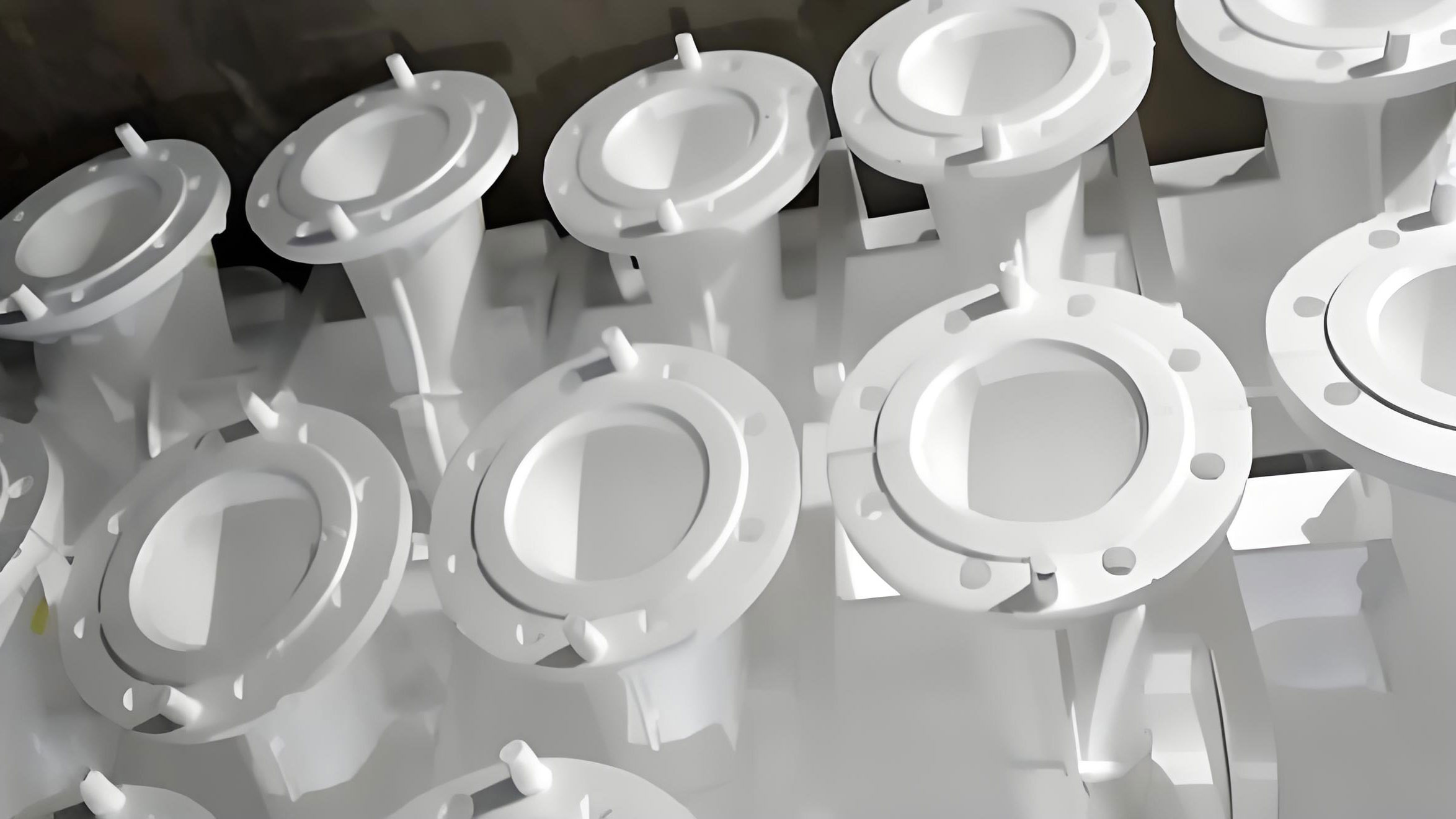
Two types of test specimens were fabricated: permeability specimens and bending strength specimens. For permeability testing, a ceramic tube was inserted and fixed into a spherical foam pattern with a diameter of 37 mm. The coating application process was identical for both specimen types. First, the foam pattern was dipped into the face coat slurry to ensure a uniform coating layer, then air-dried at 40°C for a minimum of 3 hours. Subsequently, the pattern was dipped into the stirred backup coat slurry and air-dried at 50°C for at least 3 hours. This backup coating cycle was repeated to achieve the desired number of layers as per Table 1. After the coating process was complete, the specimens underwent a firing cycle to remove the foam and sinter the coating. They were heated to 300°C and held for 30 minutes to gasify the foam, then further heated to 900°C and held for another 30 minutes to sinter the ceramic shell. This resulted in hollow, sintered shells ready for testing. The following figure shows examples of the fired specimens used in this study for lost foam shell casting evaluation.
The high-temperature gas permeability of the lost foam casting shells was measured using a principle where a constant-pressure gas is passed through the shell specimen. The pressure drop across the shell, combined with the gas flow rate, time, and shell geometry, is used to calculate permeability. The test involves placing the specimen in a furnace, introducing compressed air at a pressure (P_e) between 0.1 and 0.15 MPa, heating to the test temperature at a rate of 20°C/min, holding for 10 minutes to stabilize, and then measuring the gas flow volume (V) over a known time (t). The permeability (K) is calculated using the following formula, which accounts for the shell thickness (δ) and the internal surface area (A):
$$K = \frac{V \cdot \delta}{t \cdot P_e \cdot A}$$
Here, K represents permeability with units of m⁴/(N·min), V is the gas volume in m³, t is the time in minutes, P_e is the air pressure in Pa, δ is the shell thickness in meters, and A is the internal surface area in m². This measurement was conducted both at room temperature (25°C) and at a high temperature of 1250°C to assess performance under casting conditions.
The bending strength of the shells was evaluated using a three-point bend test on bar-shaped specimens at three different temperatures: 25°C (room temperature), 900°C, and 1250°C. The specimens were heated to the target temperature in a furnace, held for a sufficient time to ensure uniform temperature distribution, and then tested to failure. The maximum load was recorded, and the bending strength (σ) was calculated using the standard formula for a simply supported beam with a central point load:
$$\sigma = \frac{3 \cdot F \cdot L}{2 \cdot w \cdot h^2}$$
Where F is the fracture load, L is the support span, w is the specimen width, and h is the specimen thickness. This provided insights into the mechanical integrity of the lost foam casting shell at various stages of the process.
The results for the gas permeability of the lost foam shell casting coatings are presented in Figure 1 and summarized in Table 2 below. The data reveals distinct trends for room temperature and high-temperature permeability as a function of shell thickness.
| Specimen ID | Shell Thickness (mm) | Permeability at 25°C, K (m⁴/(N·min)) | Permeability at 1250°C, K (m⁴/(N·min)) |
|---|---|---|---|
| S14 | 2.94 | 0.55 | 0.47 |
| S15 | 3.96 | 0.57 | 0.58 |
| S16 | 4.42 | 0.62 | 0.95 |
| S17 | 5.58 | 0.58 | 0.83 |
The room-temperature permeability for lost foam casting shells remained relatively stable across different thicknesses, fluctuating within a narrow range of approximately 0.55 to 0.62 m⁴/(N·min). This indicates that at lower temperatures, the inherent pore structure of the coating is not significantly influenced by the overall build-up thickness. In contrast, the high-temperature permeability at 1250°C exhibited a clear increasing trend with shell thickness, rising from 0.47 m⁴/(N·min) for the thinnest shell (S14) to 0.83 m⁴/(N·min) for the thickest shell (S17). Specimen S16 showed an anomalously high value of 0.95 m⁴/(N·min), which I attribute to the presence of micro-cracks or leakage paths introduced during the specimen preparation, serving as an outlier. Excluding this point, the general trend is a near-linear increase in high-temperature permeability with thickness. This behavior can be modeled by a simple linear relationship:
$$K_{1250°C} = m \cdot \delta + c$$
Where m is the slope and c is the intercept. For the consistent data points (S14, S15, S17), the trend suggests that thicker shells in lost foam casting provide more pathways or larger interconnected porosity for gas escape at elevated temperatures, which is crucial for preventing gas-related defects during metal pouring.
The bending strength results for the lost foam casting shells are summarized in Table 3 and depicted graphically. The strength was measured at three critical temperatures to understand its evolution from handling through sintering to metal pouring.
| Specimen ID | Bending Strength at 25°C (MPa) | Bending Strength at 900°C (MPa) | Bending Strength at 1250°C (MPa) |
|---|---|---|---|
| S14 | 3.65 | 2.75 | 1.82 |
| S15 | 3.70 | 2.80 | 2.15 |
| S16 | 3.68 | 2.78 | 2.40 |
| S17 | 3.72 | 2.85 | 2.65 |
As expected, the bending strength of the lost foam casting shell decreased with increasing temperature. At room temperature, the strength was consistently high, averaging around 3.69 MPa with minimal variation across different thicknesses. This indicates that the coating provides robust handling strength for mold assembly and transportation in lost foam casting processes. At 900°C, the strength dropped to an average of approximately 2.80 MPa, again showing little dependence on thickness. This temperature corresponds to the sintering stage, where the binder systems undergo transformation, leading to a reduction in strength but still maintaining sufficient integrity. However, at the casting-relevant temperature of 1250°C, a clear trend emerged: the bending strength increased with shell thickness. The strength rose from 1.82 MPa for the 2.94 mm thick shell to 2.65 MPa for the 5.58 mm thick shell. This positive correlation can be expressed as:
$$\sigma_{1250°C} = k \cdot \delta + \sigma_0$$
Where k is a positive constant and σ_0 is the base strength. I postulate that for thinner shells, the influence of inherent defects like micro-voids, surface roughness, or coating inhomogeneities is more pronounced, acting as stress concentrators and leading to lower effective strength. As the shell thickness increases in lost foam casting, these defects are averaged out, and the material behaves more like a bulk ceramic. Furthermore, the increased thickness may provide more resistance to crack propagation through mechanisms like crack deflection or microcrack toughening within the porous structure.
To provide a holistic view, the trends for both key properties—high-temperature permeability and high-temperature strength—are plotted against shell thickness in Figure 2. This comparative analysis is vital for optimizing the lost foam shell casting process.
| Shell Thickness (mm) | Normalized High-Temp Permeability Trend | Normalized High-Temp Strength Trend |
|---|---|---|
| ~3.0 | Low | Low |
| ~4.0 | Medium | Medium |
| ~4.5 | High (with scatter) | Medium-High |
| ~5.6 | High | High |
The data reveals that both high-temperature permeability and high-temperature bending strength generally improve with increased shell thickness in lost foam casting. This presents a favorable scenario, as a thicker shell can simultaneously enhance gas venting and resist metallostatic pressure during pouring. However, practical considerations such as cost, drying time, and post-casting collapsibility must be balanced. Shells that are too thick may be difficult to remove from the casting after solidification, increasing cleaning effort and potentially causing casting damage. Production trials have indicated that shells corresponding to specimens S15 and S16 (approximately 4-5 mm thick) offer an excellent compromise. They provide adequate pre-pouring strength, good high-temperature performance, and satisfactory collapsibility, as evidenced by castings where the shell spontaneously detached upon cooling. This balance is crucial for the economic and qualitative success of lost foam shell casting.
To contextualize the permeability performance of this coating system, I compared it with data reported in other studies on lost foam casting coatings. A summary of this comparison is presented in Table 4, which consolidates findings from various literature sources.
| Coating Type / Study Reference | Typical Permeability Range (m⁴/(N·min)) | Comments |
|---|---|---|
| Conventional Lost Foam Coatings (Study A) | 0.2 – 0.4 | Often optimized for different binder systems. |
| Coatings with Organic Fibers (Study B) | 0.3 – 0.5 | Enhanced permeability due to fiber burnout. |
| Coatings for Steel Castings (Study C) | 0.25 – 0.45 | Focus on high-temperature stability. | This Study (Lost Foam Shell Casting) | 0.47 – 0.83 (at 1250°C) | Higher permeability, especially for thicker shells. |
The comparison shows that the coatings developed for lost foam shell casting in this work exhibit superior high-temperature permeability compared to many conventional lost foam casting coatings reported elsewhere. This enhanced permeability is a direct result of the tailored formulation and the multi-layer shell structure, which is designed to create an optimal pore network for gas evolution during the critical metal-pouring phase of lost foam casting.
The stability of room-temperature strength across thicknesses, converging to an average of about 3.71 MPa, is an important finding. In an ideal, defect-free material, mechanical properties should be independent of dimensions. The observed convergence suggests that for the thinner shells, the properties are initially influenced by process-induced flaws. As thickness increases in the lost foam casting shell building process, the coating application becomes more uniform, and the relative impact of surface irregularities and internal voids diminishes. Consequently, the measured strength asymptotically approaches the intrinsic strength of the coating material system. This understanding is valuable for quality control in lost foam shell casting production, indicating that maintaining consistent coating application parameters is key to achieving predictable shell strength.
Based on the comprehensive analysis of high-temperature properties, I can conclude that the investigated coating system for lost foam shell casting demonstrates an excellent combination of strength and permeability. The high-temperature permeability increases with shell thickness, providing better venting for gases. Simultaneously, the high-temperature bending strength also shows a positive correlation with thickness, offering greater resistance to mold failure. For practical applications in lost foam shell casting, I recommend a shell configuration comprising one face coat and five to six backup coats, resulting in a total thickness in the range of 4 to 5 mm. This configuration, exemplified by specimens S15 and S16, delivers robust handling strength, sufficient high-temperature integrity and permeability for successful pouring, and good collapsibility for easy shell removal after casting, thereby ensuring high-quality castings with minimal defects. The formulas and trends established here, such as $$K \propto \delta$$ and $$\sigma \propto \delta$$ at high temperatures, provide a quantitative framework for further optimization of coatings in the versatile and precise lost foam casting process.
Future work could involve more detailed microstructural analysis to correlate pore size distribution and crack propagation mechanisms with the measured properties. Additionally, testing under simulated thermal shock conditions identical to those in actual lost foam casting would provide even more relevant data for industrial application. The continuous development of such high-performance coatings is fundamental to advancing lost foam shell casting technology, enabling the production of superior cast components across various industries.