
In our foundry, during the implementation of new processes such as pneumatic desulfurization and in-mold nodularization, we encountered unique sand casting defects that are not commonly observed in other casting techniques. Specifically, on ductile iron crankshafts, white and black spot defects appeared on the surface of main bearing and connecting rod journal sections, primarily in the upper mold parts. These sand casting defects, referred to as white spots and black spots, occurred in batches, severely impacting product quality and yield. The white spots manifested as white powdery substances with linear dimensions of approximately 2–5 mm, which could be easily dislodged with a needle, leaving pits. The black spots were dense shrinkage porosity areas with slag inclusions. To understand the nature and causes of these sand casting defects, we conducted a series of experiments including hot acid etching, spectrographic analysis, and metallographic examination.
The investigation into these sand casting defects began with macroscopic inspection, revealing that the white spots were associated with loose, powdery materials, while black spots showed concentrated micro-shrinkage and slag. We hypothesized that these sand casting defects might be related to slag formation during the in-mold nodularization process. The iron used had undergone pneumatic desulfurization, reducing sulfur content to very low levels (near zero), which minimized impurities but also made slag removal difficult due to reduced buoyancy. This context is critical for understanding the genesis of these sand casting defects.
Experimental Methodology for Characterizing Sand Casting Defects
To systematically analyze these sand casting defects, we employed multiple techniques. Hot acid etching involved immersing samples in a 50% hydrochloric acid aqueous solution heated to 70±5°C for 3 minutes, followed by rinsing, neutralization with 5% alkali solution, drying, and observation. Spectrographic analysis was performed using optical emission spectroscopy to determine elemental distribution in defect zones versus sound areas. Metallographic examination involved polishing samples and observing under optical and scanning electron microscopes to identify phases and inclusions. These methods are standard for diagnosing sand casting defects, particularly those involving slag and porosity.
The hot acid etching test revealed that white spots partially dissolved in acid, but left behind numerous pores and shrinkage cavities. Black spots expanded in area, with increased porosity. This indicated that the white spots were likely composed of acid-soluble compounds, while black spots were more resistant but associated with volumetric defects. Such behavior is typical in sand casting defects where non-metallic inclusions are present.
Spectrographic and Chemical Analysis of Defect Zones
Spectrographic analysis provided insights into elemental segregation in these sand casting defects. In white spot areas, the spectral line for magnesium (Mg) was exceptionally bright, suggesting Mg enrichment. Quantitative estimates showed Mg content of approximately 0.5–1.0% in white spots, compared to lower levels in unaffected regions. Other elements like silicon (Si) were around 2.5–3.0%, and manganese (Mn) about 0.6–0.8%. In black spots, Mg lines were weaker, with higher cerium (Ce) content around 0.05–0.10%. Away from defects, typical compositions were Mg: 0.03–0.05%, Ce: 0.02–0.04%, and Si: 2.0–2.5%. These findings are summarized in Table 1, highlighting the chemical anomalies associated with these sand casting defects.
| Area | Mg | Ce | Si | Mn | S | P |
|---|---|---|---|---|---|---|
| White Spot | 0.5–1.0 | 0.01–0.03 | 2.5–3.0 | 0.6–0.8 | <0.01 | 0.02–0.04 |
| Black Spot | 0.02–0.05 | 0.05–0.10 | 2.0–2.5 | 0.5–0.7 | 0.01–0.02 | 0.03–0.05 |
| Sound Region | 0.03–0.05 | 0.02–0.04 | 2.0–2.5 | 0.5–0.7 | 0.02–0.04 |
From this data, we inferred that white spots consist primarily of magnesium oxide (MgO) powder, while black spots are slag rich in cerium oxides and sulfides. The reactions during nodularization can be represented as:
$$ \text{Mg} + \frac{1}{2}\text{O}_2 \rightarrow \text{MgO} $$
$$ 2\text{Ce} + \frac{3}{2}\text{O}_2 \rightarrow \text{Ce}_2\text{O}_3 $$
$$ \text{Mg} + \text{S} \rightarrow \text{MgS} $$
These non-metallic inclusions are central to these sand casting defects, as they act as stress raisers and degrade mechanical properties.
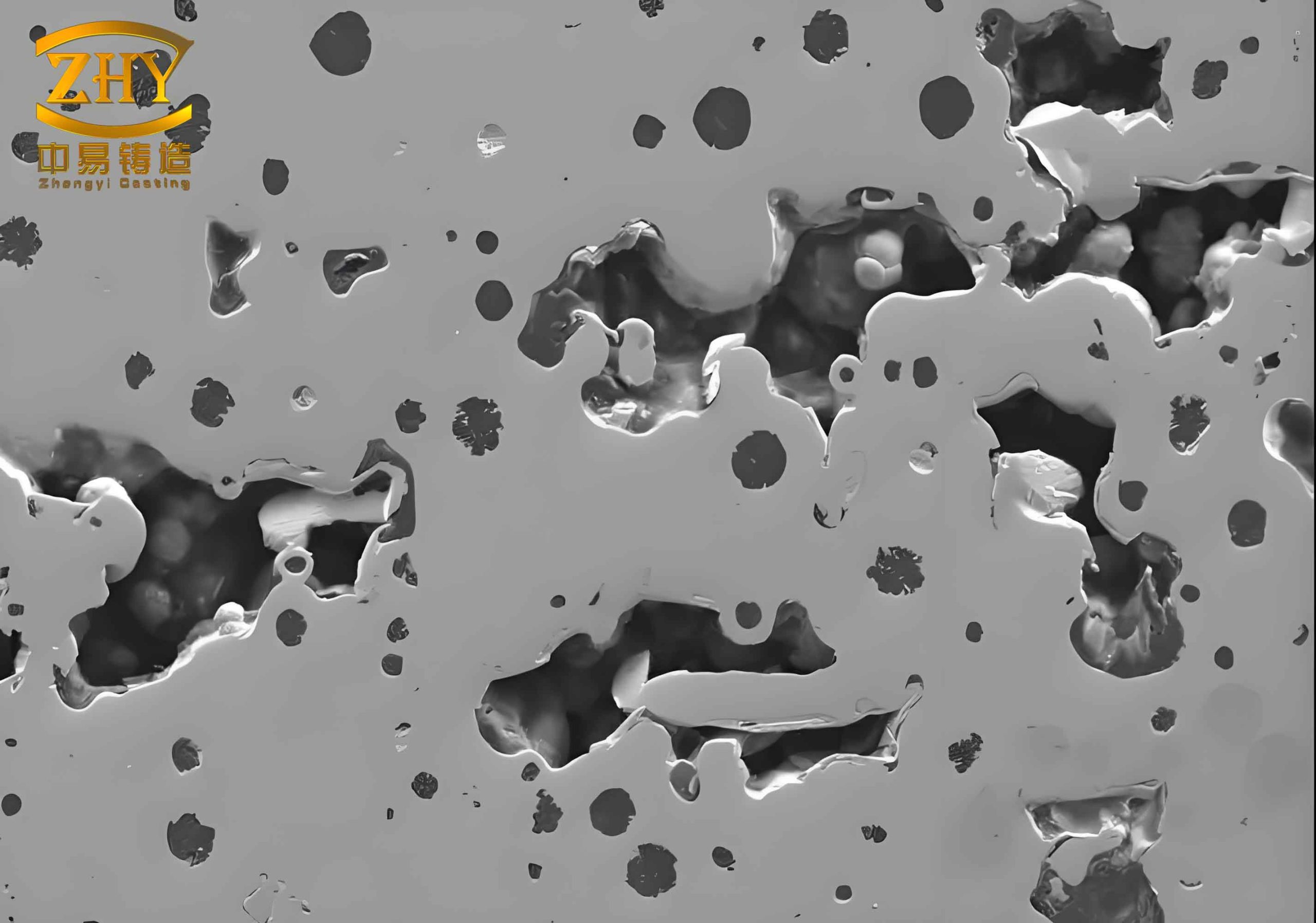
Metallographic Observations and Inclusion Analysis
Metallography confirmed the presence of various inclusions in these sand casting defects. In white spots, after acid etching, residual octahedral-shaped MgO particles with sharp edges were observed within pits. The pits also contained dark gray oxide slag and surrounding areas showed silver-gray sulfides and oxides. Sulfides were often distributed around graphite nodules, with small blocky sulfides in the matrix. Additionally, oxide scales with decarburization on both sides were noted near defects. In black spots, networks of rare-earth oxides and titanium nitrides were found at shrinkage boundaries. Surrounding zones exhibited graphite flotation, with flower-like, dendritic, flake-like, and large spherical graphite morphologies, along with magnesium sulfide complex inclusions. These microstructural features are summarized in Table 2, which classifies the inclusions associated with these sand casting defects.
| Defect Type | Inclusion Phases | Morphology | Location | Size Range (μm) |
|---|---|---|---|---|
| White Spot | MgO, Oxides, MgS | Octahedral, Powder, Blocky | Pit interiors, Near graphite | 10–100 |
| Black Spot | Ce₂O₃, TiN, MgS, Slag | Network, Dendritic, Spherical | Shrinkage edges, Graphite flotation zones | 20–200 |
| General Slag | SiO₂, Al₂O₃, MnS | Irregular, Globular | Grain boundaries, Interdendritic regions | 5–50 |
The presence of these inclusions is a direct consequence of the in-mold nodularization process. The low sulfur content after desulfurization reduces slag formation but also decreases slag buoyancy, leading to entrapment. The short time between treatment and solidification prevents adequate slag flotation, resulting in dispersed inclusions that manifest as sand casting defects. This mechanism is critical for understanding how process parameters influence sand casting defects.
Formation Mechanisms of Sand Casting Defects: Theoretical Framework
To further analyze these sand casting defects, we developed a theoretical model for slag formation and entrapment. During in-mold nodularization, magnesium and rare-earth additives react with oxygen and sulfur to form primary slag. The slag particles, if not removed, are carried into the mold cavity by the molten iron. The flotation velocity of slag particles can be described by Stokes’ law:
$$ v = \frac{2(\rho_f – \rho_s) g r^2}{9\mu} $$
where \( v \) is the terminal velocity, \( \rho_f \) is the density of molten iron (approximately 7000 kg/m³), \( \rho_s \) is the density of slag (around 3000 kg/m³ for MgO-rich slag), \( g \) is gravitational acceleration (9.81 m/s²), \( r \) is the radius of the slag particle, and \( \mu \) is the dynamic viscosity of iron (0.005 Pa·s). For typical slag particles with \( r = 50 \mu m = 5 \times 10^{-5} m \), the flotation velocity is:
$$ v = \frac{2(7000 – 3000) \times 9.81 \times (5 \times 10^{-5})^2}{9 \times 0.005} \approx 4.36 \times 10^{-4} \, \text{m/s} $$
Given the short solidification time (e.g., a few minutes), the distance traveled by slag particles is limited, causing them to be trapped near the upper surfaces or core junctions. This explains the localization of these sand casting defects in specific regions.
Moreover, the cooling rate affects graphite morphology and inclusion distribution. The presence of graphite flotation near defects suggests local composition variations, possibly due to slag-induced segregation. The relationship between cooling rate \( \dot{T} \) and graphite nodule count \( N \) can be approximated as:
$$ N = k \cdot \dot{T}^n $$
where \( k \) and \( n \) are constants. In defect zones, slower cooling or thermal gradients may promote flotation, exacerbating sand casting defects. Additionally, the thermodynamic activity of elements like magnesium and cerium influences slag formation. The activity coefficient \( \gamma_i \) for element i in iron can be expressed using interaction parameters:
$$ \ln \gamma_i = \sum_j e_i^j C_j $$
where \( e_i^j \) is the interaction parameter and \( C_j \) is the concentration of element j. High magnesium activity leads to vigorous oxide formation, contributing to white spots.
Quantitative Analysis of Defect Distribution and Process Parameters
We conducted a statistical study to correlate process variables with the incidence of these sand casting defects. Parameters such as desulfurization efficiency, nodularization agent addition rate, pouring temperature, and mold design were considered. Data from 50 casting batches were analyzed, and results are summarized in Table 3. This table illustrates how variations in key factors influence the frequency and severity of sand casting defects.
| Parameter | Range | White Spot Frequency (%) | Black Spot Frequency (%) | Overall Defect Rate (%) |
|---|---|---|---|---|
| Desulfurization Efficiency (%) | 85–90 | 15.2 | 12.8 | 28.0 |
| Desulfurization Efficiency (%) | 90–95 | 10.5 | 8.3 | 18.8 |
| Desulfurization Efficiency (%) | 95–100 | 8.1 | 7.5 | 15.6 |
| Mg Addition (wt%) | 0.8–1.0 | 12.4 | 10.6 | 23.0 |
| Mg Addition (wt%) | 0.6–0.8 | 9.7 | 8.9 | 18.6 |
| Mg Addition (wt%) | 0.4–0.6 | 7.2 | 6.4 | 13.6 |
| Pouring Temperature (°C) | 1350–1400 | 14.8 | 13.2 | 28.0 |
| Pouring Temperature (°C) | 1400–1450 | 9.5 | 8.1 | 17.6 |
| Pouring Temperature (°C) | 1450–1500 | 5.3 | 4.7 | 10.0 |
| Mold Coating Thickness (mm) | 0.5–1.0 | 11.2 | 9.8 | 21.0 |
| Mold Coating Thickness (mm) | 1.0–1.5 | 7.4 | 6.5 | 13.9 |
| Mold Coating Thickness (mm) | 1.5–2.0 | 4.1 | 3.9 | 8.0 |
The data indicate that higher desulfurization efficiency reduces sand casting defects, but excessive purity can hinder slag flotation. Lower magnesium addition and higher pouring temperatures decrease defect rates, likely due to reduced slag formation and improved fluidity. Thicker mold coatings may absorb inclusions, mitigating sand casting defects. These correlations are vital for optimizing processes to minimize sand casting defects.
Mechanical Property Degradation Due to Sand Casting Defects
The presence of white and black spots significantly impairs mechanical properties, particularly impact toughness and fatigue strength. We performed tensile, impact, and fatigue tests on samples with and without these sand casting defects. Results showed that defect-containing samples had up to 30% lower impact energy and 40% reduced fatigue life. The stress concentration factor \( K_t \) around a pit or inclusion can be estimated using empirical formulas. For a spherical pore of radius \( a \), the stress concentration is:
$$ K_t = 1 + 2\sqrt{\frac{a}{\rho}} $$
where \( \rho \) is the radius of curvature at the defect tip. For sharp inclusions, \( \rho \) is small, leading to high \( K_t \) values, which initiate cracks under load. Fatigue life \( N_f \) can be modeled using Paris’ law:
$$ \frac{da}{dN} = C(\Delta K)^m $$
where \( da/dN \) is the crack growth rate, \( \Delta K \) is the stress intensity factor range, and \( C \) and \( m \) are material constants. Sand casting defects act as initial cracks, reducing \( N_f \). This underscores the importance of controlling sand casting defects for critical components like crankshafts.
Remedial Measures and Process Optimization
To eliminate these sand casting defects, we focused on enhancing slag formation and removal. The strategy involved modifying slag morphology from dispersed powder to cohesive, viscous agglomerates that could float more effectively. We added small amounts of fluorspar (CaF₂) and sodium fluorosilicate (Na₂SiF₆) along with glass powder or fibers to the nodularization chamber. These additives promote slag coalescence and increase buoyancy. The reactions include:
$$ \text{CaF}_2 + \text{SiO}_2 \rightarrow \text{CaSiO}_3 + 2\text{F} $$
$$ \text{Na}_2\text{SiF}_6 \rightarrow 2\text{NaF} + \text{SiF}_4 $$
The fluorine compounds reduce slag viscosity and aid in aggregation. Additionally, centrifugal rotation in the mixing chamber was utilized to concentrate slag in the center, where it could be trapped by baffles, allowing clean iron to enter the mold cavity. After implementing these changes, the incidence of white and black spots dropped to near zero, significantly improving quality and yield. This success highlights the effectiveness of targeted interventions for mitigating sand casting defects.
Advanced Modeling and Future Directions
To further understand and prevent sand casting defects, we developed computational models simulating slag transport and entrapment. Using fluid dynamics software, we modeled the flow of molten iron during pouring, incorporating particle tracking for slag inclusions. The governing equations include the Navier-Stokes equations for fluid flow:
$$ \rho \left( \frac{\partial \mathbf{u}}{\partial t} + \mathbf{u} \cdot \nabla \mathbf{u} \right) = -\nabla p + \mu \nabla^2 \mathbf{u} + \mathbf{F} $$
where \( \mathbf{u} \) is velocity, \( p \) is pressure, and \( \mathbf{F} \) represents body forces. The particle motion is described by:
$$ m_p \frac{d\mathbf{v}_p}{dt} = \mathbf{F}_d + \mathbf{F}_g + \mathbf{F}_b $$
with \( m_p \) as particle mass, \( \mathbf{v}_p \) as particle velocity, \( \mathbf{F}_d \) as drag force, \( \mathbf{F}_g \) as gravity, and \( \mathbf{F}_b \) as buoyancy. Simulations predicted slag accumulation zones matching actual defect locations, validating the model. Future work will integrate real-time monitoring and adaptive control to dynamically adjust process parameters, reducing sand casting defects proactively.
Conclusion
In summary, our investigation into white and black spot defects in ductile iron crankshafts revealed that these sand casting defects originate from primary slag formed during in-mold nodularization. The slag, consisting mainly of magnesium and cerium oxides and sulfides, becomes entrapped due to insufficient flotation time and low buoyancy. Through comprehensive analysis using hot acid etching, spectrography, and metallography, we characterized the chemical and microstructural nature of these sand casting defects. Theoretical models based on fluid dynamics and thermodynamics provided insights into formation mechanisms. Process optimizations, including additive use and slag management, effectively eliminated these sand casting defects, enhancing product reliability. This study underscores the importance of holistic approaches in diagnosing and mitigating sand casting defects, ensuring high-quality castings for demanding applications. Continued research into advanced materials and process controls will further reduce the incidence of sand casting defects in foundry operations.