When setting simulation parameters in ProCAST preprocessing section, the following aspects need to be adjusted:
(1) The material of cold iron is set as 35 steel, and the pouring number of interface heat exchange between cold iron and casting is set as H = 1000W / (M2 · K).
(2) The heat generating material is exothermic, the density is 500kg / m3, the ignition temperature is 600 ℃, and the heating capacity is 1000kj / kg.
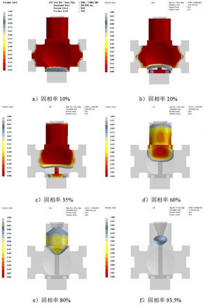
Figure 1 shows the distribution of solid increase rate. It can be seen from the figure that the solidification rate of the contact part of the cold iron is significantly accelerated due to the chilling effect of the external cold iron. When the solid increase rate is 10%, all four corners of the casting have solidified, which reduces the defects such as porosity and continuous carburization. When the solid increase rate is 20%, the liquid increasing zone between the bottom of the casting and the runner has been disconnected, which greatly reduces the influence of pouring on the sequential solidification. When the solid increase rate reaches 60%, the casting has solidified all around, and the liquid increasing area concentrates on the middle and upper part of the casting and the inner part of the riser. When the solid increase rate reaches 93.5%, all the increasing areas of isolated liquid are concentrated in the riser, and all the castings have been solidified.

The internal solidification of the casting follows the sequence from the beginning to the end, and there is no isolated liquid increasing area, which indicates that the internal feeding of the casting is good and there is no shrinkage porosity defect. In addition, because the top of the riser is covered with heating material, the heating material continuously releases a large amount of heat energy in a short time after ignition, thus prolonging the solidification time of the riser. It can be seen from Fig. 1 that even when the solid increase rate reaches 20%, the liquid increasing zone in the riser still maintains a high temperature, and the top of the riser does not start to solidify until the solid increase rate reaches 35%.

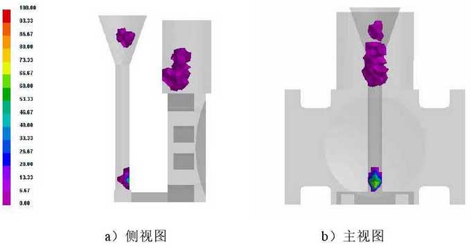
Fig. 2 shows the prediction diagram of shrinkage cavity and porosity position. The results show that the shrinkage cavity and porosity appear in the riser and runner (purple area in the figure), and the density of casting group is good, which is consistent with the prediction of solid increase rate diagram.

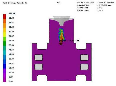
The shortest vertical distance between the shrinkage cavity and the top of the casting (i.e. the safe height of the riser) is 2.32cm, as shown in Fig. 3. This simulation result almost reaches the limit value.
