
1. Selection of parting surface and pouring position of casting
According to the structural characteristics of the castings, the bottom two planes of the castings are the important working faces. There are cavities in these two planes, which require high positioning requirements.Sand cores need to be designed between two cavities and two ribs. Therefore, when choosing the parting surface, the two separated bottom surfaces should be taken as the important surface to facilitate the placement of the core and reduce the number of cores.When choosing the pouring position of castings, the pouring position and parting surface should be set on a plane with the main body of the castings in the upper box. This can reduce misalignment, facilitate the setting of the pouring system, reduce the later process cost and improve the quality of the castings.In addition, the selection of the pouring position should ensure that the critical working face of the casting is down or side elevation, and that the number of cores is minimized [4].In conclusion, 4 schemes as shown in Figure 2 are designed for comparative analysis.
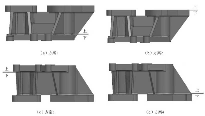
In scheme 1 and 2, two important planes are placed on the upper surface (Figures 2a and b), considering that these two planes are not suitable for machining and that more cores are required for both casting schemes, Scheme 1 and Scheme 2 are excluded; in contrast, Scheme 3 and Scheme 4, two important planes are placed on the bottom surface (Figures 2C and d), which facilitates the setting of upper and lower cores and reduces the number of cores.The top surface is an irregular surface with many reinforcing ribs and cylindrical protruding blocks. The protruding blocks can collect defects, so that the defects on the upper surface of the casting are concentrated in the cylindrical protruding blocks. A riser is set at the cylindrical protruding blocks so that the defects are concentrated on the riser, which reduces the defects of the casting, improves the precision of the casting and also improves the yield of the casting.The castings belong to small castings and are formed by one box and two pieces. It can be seen from scheme 3 and 4 that liquid metal in scheme 4 is injected into the cavity from the bottom of the castings while liquid metal in scheme 3 is injected into the cavity from the top of the castings. Liquid metal will exert a great impact on the bottom of the castings and easily cause sand scouring, while bottom pouring in scheme 4 can avoid oxidation and coiling caused by splashing of liquid metal.Therefore, scheme 4 is the best one.
2. Design of gating system
According to the structural characteristics of the castings, the bottom lapping side pouring system was designed, and the common funnel-shaped pouring cup was selected as the pouring cup.The cross section of the gating system is trapezoid, and the inner gating is flat trapezoid. Slag risers are set at both ends of the cross gating system.The metal liquid flows from the straight runner to the cross runner through sharp bends. Therefore, a slag collecting bag is set at the lower end of the straight runner. The slag collecting bag can not only filter the scum in the metal liquid, but also buffer the metal liquid to a certain extent.The casting requires that the pouring system has certain slag removal capacity. Therefore, a filter screen with hole size of 2.5 mm x 2.5 mm is set at the bottom of the straight gate.
3. Determination of casting process parameters
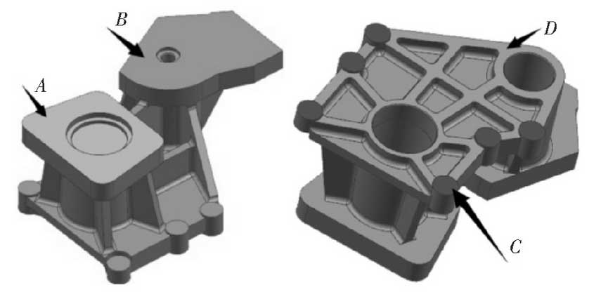
In order to ensure the dimensional accuracy of the casting machined surface, a certain thickness will be added to the machined surface during the casting process design.The casting material selected is ductile iron, and the machining grade range is E-G.Combining with the pouring position of the casting, different grades of “processing allowance grade” are set for different parts of the casting.The position of machining allowance for castings is shown in Figure 3.The casting tolerance grade of this castings is CT11. Calculated machining allowance on each side is 1.5 mm on surface A, 1.5 mm on surface B, 0.5 mm on surface C and 2 mm on surface D.
Metal shrinkage occurs when changing from liquid to solid. There are 9 reinforcing ribs on the casting. The setting of reinforcing ribs can effectively prevent the casting from shrinking. The casting shrinkage rate of this casting is set at 0.8%.In order to take out the pattern or core easily, a certain degree of slope should be left in the direction of the pattern and core box. The whole casting is wrapped by the core and the whole is composed of cores. Therefore, the drawing slope of this casting is set at 0 35′.