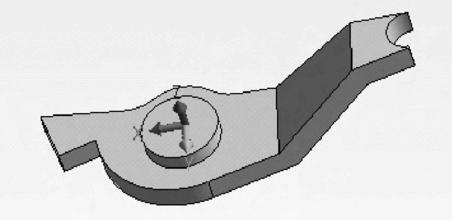
Taking the profile bar on a track powered rolling car as an example, the material of the steel casting is zg230-450, the gross weight of a single piece is 2kg, the total mass of the pouring riser is 5kg, the pouring temperature is 1560 ~ 1590 ℃, the pouring time is 8 ~ 11S, and the riser height is 100mm. See Figure 1 for the model of the steel casting.
The part information extraction model is imported into the system, and the part information is extracted to obtain the overall volume, area, contour length and quality of steel castings, and to obtain the overall modulus of steel castings.
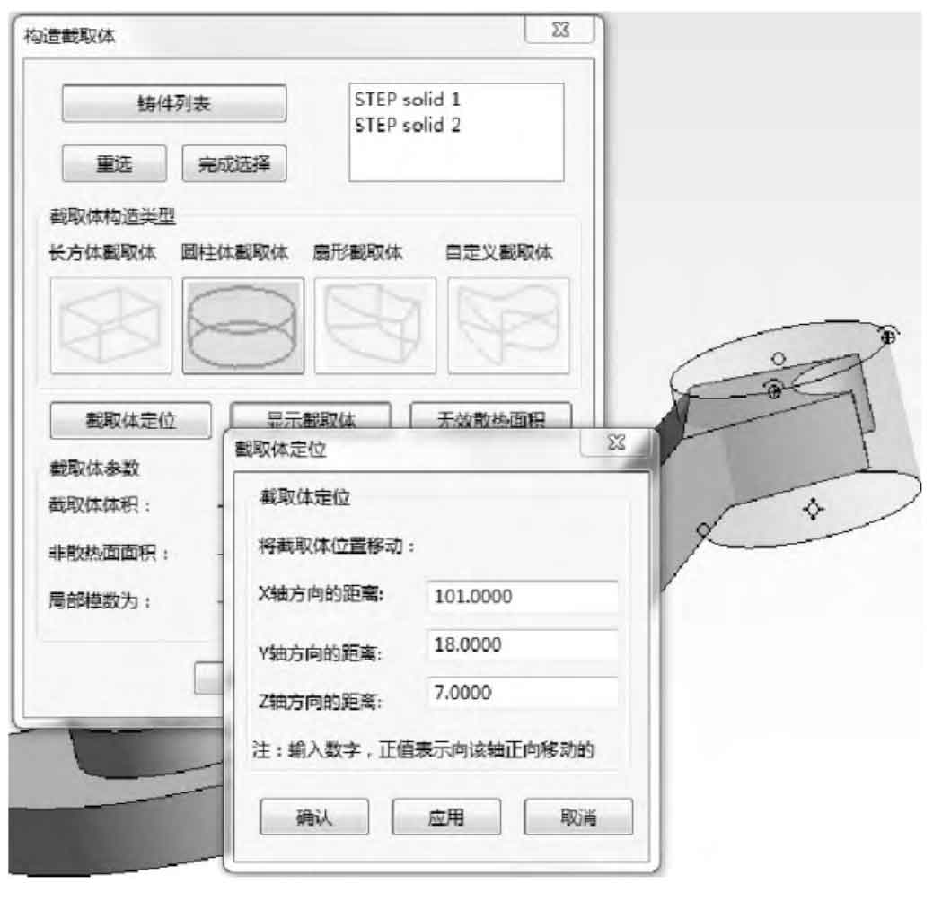
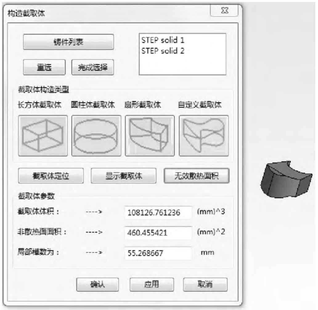
To calculate the local modulus of steel castings, first select the appropriate type of interceptor tool. In this example, select the cylindrical interceptor. Figure 2 shows the construction process of interceptor. Set the size and position of the interceptor, as shown in Figure 2a, and obtain the interceptor of the steel casting. Select the steel casting to obtain the volume of the interceptor, and select the non radiating surface of the interceptor of the steel casting to obtain the non radiating area of the local interceptor of the steel casting, and then obtain the local modulus of the steel casting, as shown in Figure 2b.
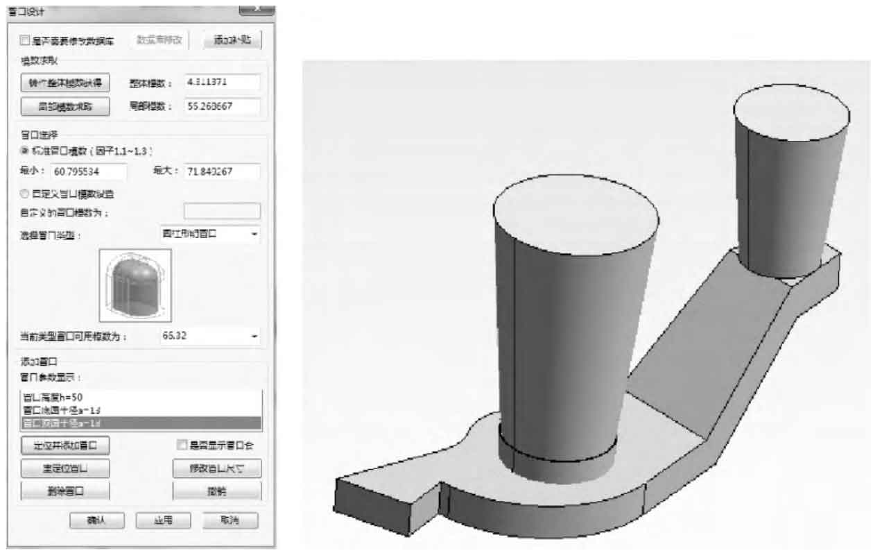
The riser type and parameters of steel castings shall be selected through the above methods. The riser type shall be cylindrical open riser. After the above operations are completed, the riser shall be positioned. The final riser system is shown in Figure 3.
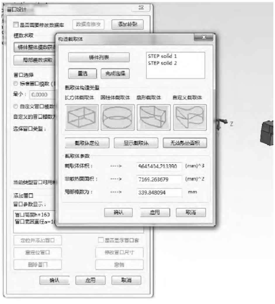
Taking the upper box of a typical steel casting tamping machine with the model of dc-32 as an example, the density, total area, outline dimension, casting volume, mass, total mass of molten steel and other information of steel castings are shown in Figure 4.

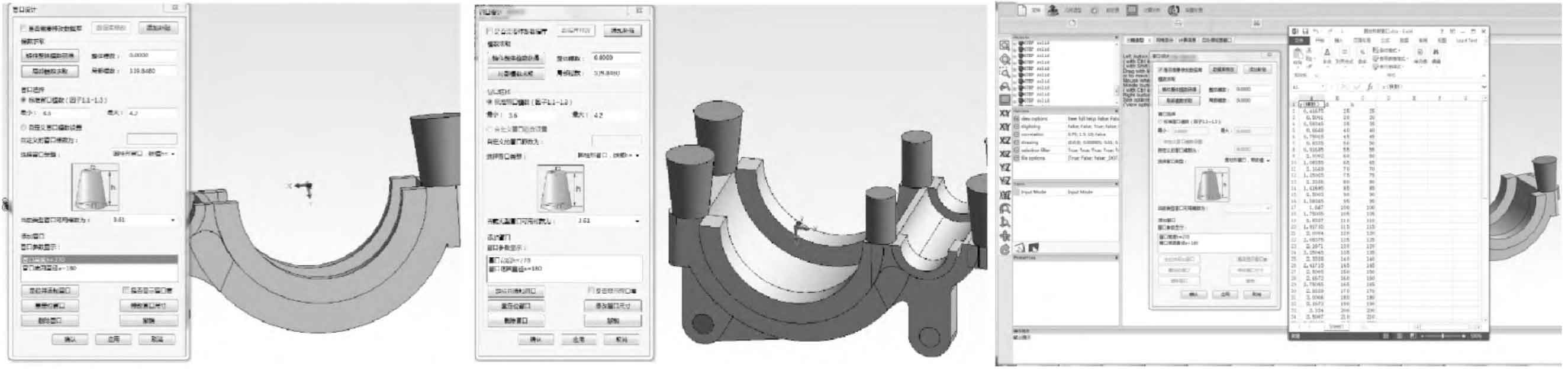
The module design of riser system for steel castings is divided into two parts, the first is the calculation of local modulus of steel castings, and the second is the design of riser system. When calculating the local modulus of steel castings, the process design only needs to select the most convenient interceptor tool according to the type of steel castings, set the size and position, then select the interceptor tool and steel castings, and click the “obtain interceptor of steel castings” button to obtain the local interceptor of steel castings. Figure 5 shows the setting tools for steel casting interceptors and casting local interceptors. According to the principle of modulus method, modulus is the ratio of volume to effective heat dissipation area. Therefore, before calculating the local modulus of steel castings, it is necessary to select the non heat dissipation surface on the steel castings’ intercepted body, and click the “invalid heat dissipation surface” button. The system can calculate the volume, invalid heat dissipation area and local modulus of the intercepted body according to the modulus method calculation formula.
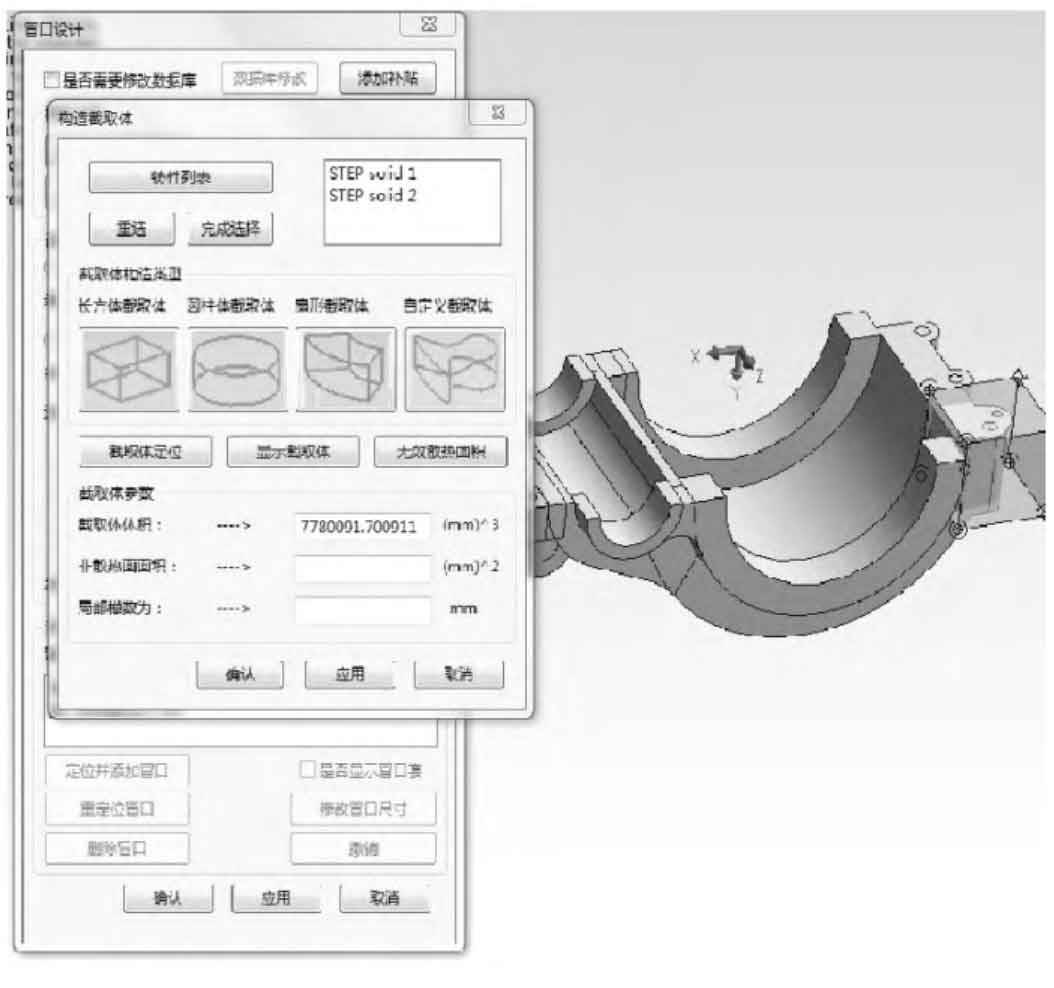
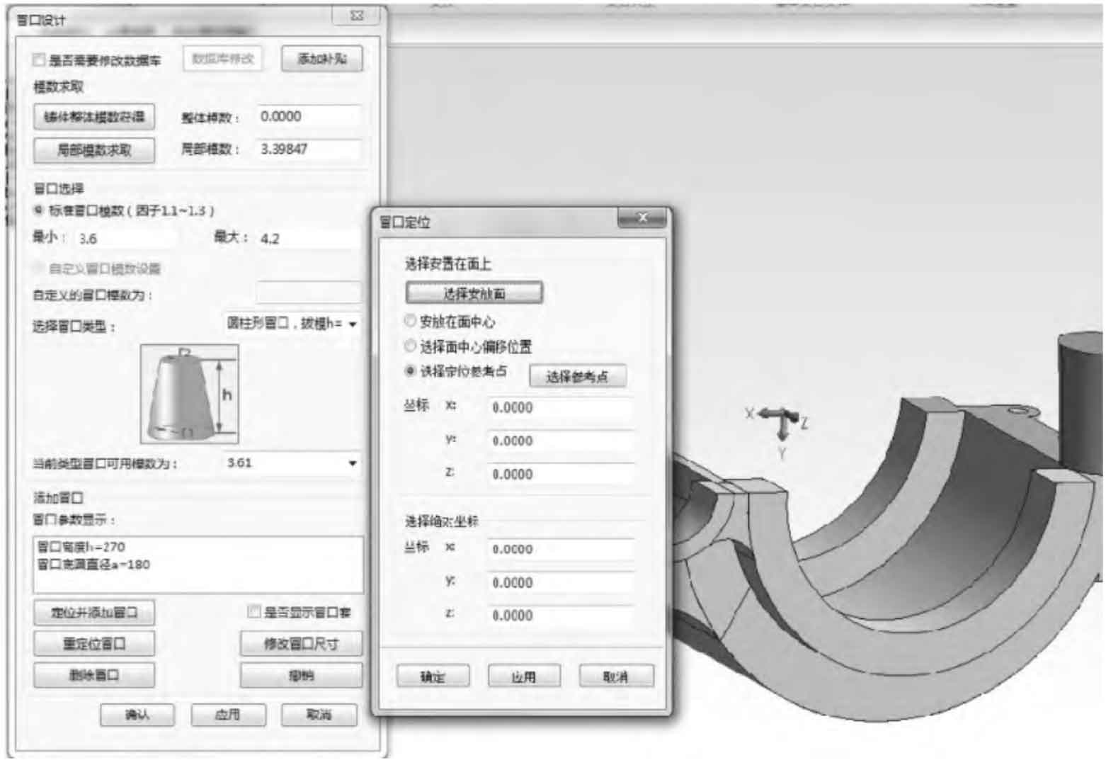
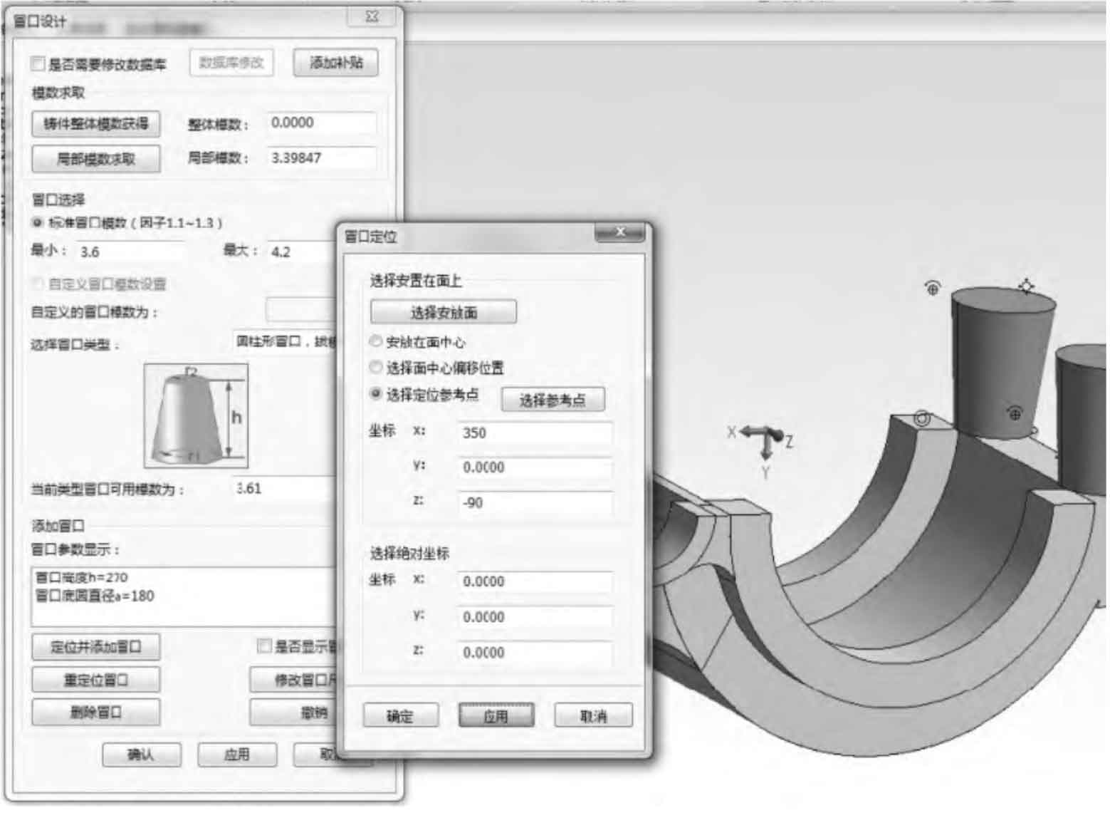
After the riser modulus range is obtained according to the local modulus of steel castings, the system matches the riser database according to the riser modulus range, and retrieves all riser types with riser modulus in the riser database; After the designer selects the riser type, the system will match it to the riser database of this type again according to the selected riser type, obtain the values of all riser modules within the riser module range, and then feed them back to the interface for the designer to select; After the riser module is determined, the system will feed back the riser size corresponding to the riser module to the operation interface for riser modeling and positioning. See Figure 6 for the riser design operation interface and its effect. If the process design thinks that it is necessary to modify the riser size parameters of the riser database before the riser system design, you can click “database modification” on the riser design interface to open the riser excel table of the riser database and modify the riser database data, as shown in Figure 6C. For the generated riser model, the positioning system can conveniently locate the riser, as shown in Figure 7.
The process design can locate the riser of steel castings according to the positioning habit. Select to place the riser on a specific surface. Just click the “select placement surface” button on the positioning interface, and click the plane to be placed. The selected plane will be highlighted, as shown in Figure 7a. As the placement plane is an irregular plane, if the riser is placed in the center of the plane, the riser position of the steel casting is far away from the hot spot, which may not be well fed. Therefore, the riser is placed at the hot spot when calculating the local modulus of the steel casting. Then take the center of the circle where the large circular arc is located as the reference point and select the reference distance to locate the riser, as shown in Figure 7b.