
In the early stage of new casting product development, the required number of samples is usually small. Traditional casting methods require the investment in permanent metal molds, which are expensive and have a lead time of 1.5 to 3 months. If the customer changes the drawing during the development phase, the casting process often needs to be modified, and sometimes the mold itself must be altered. When the mold modification is difficult or impossible to repair, the mold may be scrapped, causing significant economic loss. Moreover, developing a metal mold from process design to final machining is time‑consuming and cannot quickly respond to customer demands.
Traditional casting of geometrically complex parts often encounters the problem of pattern withdrawal. To overcome this, a large number of sand cores or loose pieces are required, needing several core boxes to produce and assemble cores. This makes the process complicated and results in lower dimensional accuracy. 3D sand printing technology can effectively solve these problems by enabling mold‑less casting and rapid sand mold production.
As an emerging technology, 3D sand printing has clear advantages. It is almost unrestricted by geometric complexity and can produce highly intricate components. In this project, I combined 3D sand printing with simulation technology to achieve the rapid development of a multi‑curved impeller body casting sample.
1. Casting Process Design
1.1 Casting Structure Analysis
The impeller body casting is required by the customer to be made of QT500‑7 ductile iron. The maximum overall dimensions are Φ660 mm × 202 mm, with a casting mass of 105 kg and a blade wall thickness of 21 mm. The casting has a large hot spot at the center. There are six twisted blades. Using a conventional core assembly process, each blade would require at least two sand cores, resulting in a minimum of 12 sand cores for the entire casting. After assembly and pouring, the gaps between cores would produce excessive flash, making grinding difficult. Over‑grinding could easily lead to non‑smooth transitions on the curved blade surfaces, affecting the performance of the impeller. Due to the large wall thickness differences, internal shrinkage defects are likely, so rapid pouring is necessary.
1.2 Gating and Riser Design
Considering the structural characteristics and material properties of the impeller body, rapid pouring and adequate feeding of the thick sections are essential. I adopted the following riser design and verified it by simulation:
- First, a central thick cylindrical structure with a thickness of 180 mm was considered. A single top riser design was simulated, but the riser became extremely large; the riser neck diameter had to be almost equal to the central cylinder diameter to draw shrinkage porosity into the riser. Such a massive riser placed directly on the large hot spot would create an even larger artificial hot spot, causing local overheating and coarse microstructure at the riser root, making subsequent riser removal difficult.
- Second, in order to meet the requirement of rapid pouring, if ingates were placed on each blade, they would create irregular blade shapes and severe turbulence in the mold cavity. Moreover, the subsequent cleaning would cause blade grinding problems.
- Based on these unfavorable factors, I designed two top risers for pouring and feeding, and placed a chill at the bottom of the central hot spot to achieve directional solidification. The pouring scheme is shown in the figure below. Two small risers are located at the top of the central cylinder, but not at the exact center. This arrangement helps to feed the hot spot while minimizing the artificial hot spot and easing riser removal. In addition, a chill is set at the bottom of the central cylinder to accelerate cooling and promote directional solidification. Foam ceramic filter blocks are placed on top of both small risers, serving as runners that filter the molten iron and also act as flow stabilizers. Because pouring through only one riser may damage the filter block, I placed filter blocks in both top risers and alternated the pouring stream between them during casting.
The solidification simulation result showed that shrinkage porosity and shrinkage cavities could be transferred into the risers. Although some minor shrinkage defects remained at the riser neck roots, based on experience, because the risers were directly used for pouring, they were hot enough to ensure the defects would be confined within the riser body and not affect the casting soundness.
| Parameter | Value / Observation |
|---|---|
| Shrinkage porosity in casting | None |
| Shrinkage porosity in riser neck | Small amount, can be removed |
| Hot spot location | Transferred to riser |
| Solidification time | Reduced by chill effect |
2. 3D Sand Printing Molds
2.1 Mold Design for 3D Sand Printing
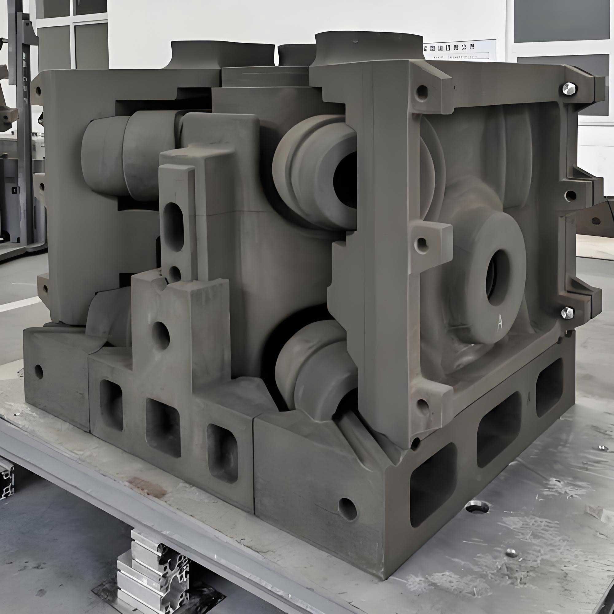
Based on the casting process plan, I designed the sand molds for 3D sand printing. The mold digital model is shown in the figure above. The parting line was placed at the middle of the blade height, with a sand thickness of 40–50 mm. Three sand cones were designed at the parting surface for self‑locating. To reduce printing volume and time, I minimized the sand mold wall thickness while maintaining sufficient strength. Handles and lifting recesses were reserved on the side surfaces of the mold for handling and closing. Exhaust holes were designed on the parting plane, not connected to the cavity, to allow gases generated during pouring to escape. The casting shrinkage rate for the impeller body was set to 0.8%, and an allowance of 0.2 mm was preset for the coating layer.
Using 3D sand printing, only two sand molds (upper and lower) were required to form the twisted blade shapes. In contrast, traditional casting would need numerous cores to create such undercut shapes. Fewer mold parts means higher accuracy, less flash, and cleaner external surfaces. This demonstrates that 3D sand printing enables mold‑less casting and flexible production, reduces sample manufacturing cost, and shortens the lead time to about 20 days.
| Aspect | Traditional Core Assembly | 3D Sand Printing |
|---|---|---|
| Number of cores | At least 12 | 0 (only upper and lower molds) |
| Dimensional accuracy | Lower, cumulative assembly error | CT7–CT8 per mold part |
| Flash | High, due to core gaps | Minimal |
| Lead time | 1.5–3 months (with metal molds) | ~20 days |
| Surface quality | May require excessive grinding | Excellent |
2.2 Rapid Mold Production
The impeller body casting was an experimental part for a customer’s product development, and three pieces were required. I used 3D sand printing to manufacture the sand molds. The sand core tolerance grade was executed to CT7–CT8, and the sand strength requirement was a room‑temperature tensile strength of at least 1.5 MPa. After the sand molds were delivered, I brushed an alcohol‑based coating on the mold cavity surfaces, controlling the coating thickness at 0.15–0.2 mm, and then ignited the alcohol for drying. The chill was made of 45 steel, and its working surface was also coated with the alcohol‑based coating and flame‑dried.
| Parameter | Value |
|---|---|
| Sand mold tolerance grade | CT7–CT8 |
| Sand tensile strength (RT) | ≥1.5 MPa |
| Coating type | Alcohol‑based |
| Coating thickness | 0.15–0.2 mm |
| Casting shrinkage | 0.8% |
| Coating allowance | 0.2 mm |
| Chill material | 45 steel |
The image below shows the 3D-printed sand mold, the brushed mold, and the ceramic filters/chills used in this work.
3. Pouring and Machining Verification
Because the mold with sand weighed up to 126 kg, I placed the closed mold in a flask and backed it with sand to prevent run‑out during pouring. After pouring and cooling, the casting was knocked out, risers were cut off, and the casting was fettled and shot blasted. The dimensional inspection passed, the surface was clean, and ultrasonic inspection detected no internal defects. The figure shows the casting after shakeout. Three poured pieces were sent to the customer for machining verification, and all were qualified. The finished sample is shown in the figure later.
| Inspection item | Result |
|---|---|
| Dimensional inspection | Conformed to drawing |
| Surface quality | Smooth, no visible flash |
| Ultrasonic testing | No internal defects |
| Machining verification | Passed |
| Customer feedback | Satisfied |
4. Conclusion
By applying 3D sand printing combined with simulation technology, I successfully developed the impeller body casting quickly. Three consecutive castings were produced with excellent surface quality and successful machining verification. The customer gave positive feedback.
3D sand printing has bright prospects for the rapid development of complex castings, especially for sample preparation. It enables low‑cost and high‑precision rapid manufacturing of complex products. The application of 3D sand printing will keep expanding in the foundry industry, accelerating innovation in new product development and offering a competitive advantage in the era of customized manufacturing.
To further illustrate the benefits of 3D sand printing in this impeller development, I summarize the cost and time savings in the table below. Although the numerical values may vary based on specific suppliers and regions, the qualitative benefits are consistent with this project’s experience.
| Item | Traditional metal mold | 3D sand printing |
|---|---|---|
| Initial tooling cost | High | Low (no hard tooling) |
| Lead time | 1.5 – 3 months | ~20 days |
| Design change accommodation | May need mold rework/scrap | Simple digital modification |
| Complex geometry capability | Limited by pattern draft | Nearly unlimited |
| Number of mold parts | Multiple core boxes | Often only two molds |
| Assembly error | Accumulative | Minimal |
| Surface finish | Good but flashes likely | Excellent, fewer flashes |
In this development, the casting process parameters were optimized with the help of numerical simulation. The feeding design relied on the modulus calculation. For the central heavy section, the modulus was calculated as:
$$ M = \frac{V}{A} $$
where V is the volume and A is the cooling surface area. The chill was designed to increase the local cooling rate, effectively reducing the local modulus. The riser size was calculated to ensure that the riser modulus is larger than the casting modulus in the region it feeds. In simple terms:
$$ M_{\text{riser}} = f M_{\text{casting}} $$
with f typically between 1.1 and 1.2 for ductile iron. For this impeller, f was chosen as 1.15, and the simulation verified that this was sufficient.
Another important formula used in the gating design was the flow rate through the ceramic filter. The pouring time was determined from the casting mass and the average filling rate. For ductile iron, a rapid pouring rate is essential. The relationship can be expressed as:
$$ t_p = \frac{C_{\text{rate}}}{\sqrt{m}} $$
where m is the total pouring mass and Crate is a constant based on the casting shape and wall thickness. The two risers with ceramic filters enabled a controlled filling rate of about 2.2 kg/s, which provided a smooth mold filling while satisfying the rapid pouring requirement.
The dimensional accuracy of the 3D sand printing process can be estimated by the following tolerance relation:
$$ T_{\text{CT}} = T_{\text{base}} \cdot D^{1/3} $$
where Tbase is the basic tolerance unit and D is the nominal dimension. Executing CT7–CT8 for the impeller body (diameter 660 mm) resulted in a tolerance range of about ±1.2 mm, which met the blueprint requirements for the sand mold. The final machined casting retained sufficient stock and alignment.
The sand strength requirement was specified as a minimum tensile strength of 1.5 MPa. This value ensures that the mold can withstand the static pressure of molten iron. The pressure at the bottom of the mold can be calculated by:
$$ P = \rho g h $$
where ρ is the density of liquid iron (about 6800 kg/m³), g is gravitational acceleration (9.81 m/s²), and h is the ferrostatic head. For a mold height of about 0.3 m, the maximum pressure is approximately 20 kPa, far below the tensile strength of the printed sand. Yet, the strength margin was necessary to resist thermal stresses and handling loads.
In addition to the mechanical strength, the gas permeability of the 3D printed sand mold plays a role in avoiding penetration defects. The designed venting holes were positioned on the parting plane to allow gas evacuation. The vent cross‑sectional area was roughly estimated to be 1/10 of the mold cavity surface area, which proved sufficient in practice.
The whole development process can be summarized in the following step‑by‑step workflow:
| Step | Action | Method / Tool |
|---|---|---|
| 1 | Analyze casting geometry and identify manufacturing difficulties | 3D model, wall thickness analysis |
| 2 | Design gating and feeding system | Riser modulus calculation, chill design, ceramic filters |
| 3 | Verify by solidification simulation | Simulation software |
| 4 | Design 3D sand mold digital model | CAD, add locating cones, vents, lifting recesses |
| 5 | Send to 3D sand printing service | Printing with CT7–CT8 tolerance |
| 6 | Brush coating and dry | Alcohol‑based coating, flame ignition |
| 7 | Assemble molds, place chills and filters, back up with sand | Manual, ensure seal |
| 8 | Pour ductile iron QT500-7 | Alternate pouring between two risers |
| 9 | Shakeout, fettling, shot blasting | Standard foundry operations |
| 10 | Inspection and machining verification | CMM, ultrasonic test, customer machining |
In this case, the use of 3D sand printing eliminated the need for any physical pattern or core box. This was particularly valuable because the impeller’s twisted blades would have made pattern withdrawal nearly impossible. With the traditional approach, a multi‑part pattern with loose pieces and a large number of cores would have been necessary. The tooling cost for such a complex pattern was estimated to be several times higher than the 3D sand printing cost for three sample castings. In addition, the time to produce the first sample was reduced by more than 60%. This is a typical example of how additive manufacturing can accelerate new product introduction in the foundry industry.
Furthermore, the digital nature of 3D sand printing allows for fast design iterations. If the customer changes the blade profile or the hub dimensions, the sand mold model can be updated in minutes and re‑printed, without any additional tooling. This agility is a game‑changer for prototype casting development. In this project, no design changes were required after the initial printing, but the capability was nevertheless helpful because the gating system was modified twice during the simulation phase. The design modifications were applied to the CAD model before any physical mold was made, which demonstrates the synergy between simulation and 3D sand printing.
Another important consideration was the surface finish of the printed mold. After coating, the surface roughness reached Ra 12.5 μm, which is sufficient for most iron castings. The coating prevented sand erosion and metal penetration. The alcohol‑based coating was chosen for its convenience: it can be applied by brushing, quickly dried with a flame, and provides a good surface after the alcohol burns off. The coating thickness of 0.15–0.2 mm was designed to compensate for the slight surface porosity of the 3D printed sand. Too thick a coating would have reduced the dimensional accuracy, while too thin a coating might have caused sand adhesion.
The thermal properties of the 3D printed sand mold are slightly different from conventional furan‑resin sand molds. The printing process uses a similar binder chemistry, but the distribution of the binder may vary. For ductile iron, a small amount of sulfur from the sand can affect the graphite nodule count at the surface. Therefore, the coating must act as a barrier. The 0.2 mm coating proved adequate to prevent surface sulfur contamination. The castings exhibited a fully ferritic/pearlitic structure in the thin sections and a good nodularity above 85%.
One of the technical challenges during pouring was the possibility of mold spalling due to the high velocity of molten iron. The ceramic foam filters placed in the riser tops significantly reduced the turbulent inlet velocity. The filters also trapped slag and dross, ensuring a clean casting. The two‑riser pouring strategy allowed the second riser to be used when the first filter became partially blocked. In practice, I poured about two‑thirds of the molten metal through the first riser and the remaining one‑third through the second. This prevented excessive flow through a single filter and minimized the risk of filter clogging.
From a quality point of view, the ultrasonic test was particularly important for this impeller because the central hub is subject to high stress during operation. Any internal shrinkage porosity would be unacceptable. The simulation predicted no shrinkage in the hub, and the ultrasonic results confirmed it. The chill at the bottom of the hub influenced the temperature gradient such that the last solidifying liquid was always located within the riser neck. The small amount of porosity at the riser neck root was totally removed when the risers were cut off, leaving a clean hub surface.
The machining verification performed by the customer gave valuable feedback. The six blades were machined to the final profile, and the geometry deviations were within ±0.3 mm, which is quite good for a sand casting. The customer was particularly impressed by the smooth transition on the blade surfaces. In traditional core assembly, misalignment between cores often creates steps or fins on the blade, which can disturb the fluid flow. With 3D sand printing, the entire blade shape is formed in a single mold cavity, so there are no parting lines crossing the blade airfoil (the parting plane lies at the middle of the blade height, but the blade surfaces are continuous across the mold cavity due to the geometry of the mold). Actually, the parting plane at the blade middle does create a thin flash around the blade edge, but because the two mold halves are precisely located by sand cones, the flash is minimal and easy to remove. The blade profile remains smooth after grinding.
In summary, the application of 3D sand printing in the development of this impeller body casting fully validated the following points:
- 3D sand printing can produce sand molds for complex castings without any mold tooling.
- Combining 3D sand printing with casting simulation reduces risk and improves first‑time success.
- Rapid prototype samples can be delivered in weeks rather than months.
- Surface quality and dimensional accuracy are comparable or better than traditional sand casting processes that use multiple cores.
- The cost effectiveness is excellent for low‑volume production and prototyping.
Finally, I recommend that foundries consider 3D sand printing as a standard tool for new product development, especially when the casting geometry is complex, the quantity is low, and the time‑to‑market is critical. Although 3D sand printing may not replace high‑volume casting production due to its lower productivity, it perfectly fills the gap for agile manufacturing of sample castings and single complex castings. My experience with this impeller body casting illustrates the bright future of 3D sand printing in the foundry industry.