
In recent years, as a professional involved in foundry processes, I have observed the rapid development of centrifugal ductile iron pipes. The production of ductile iron pipelines, especially large-diameter ones, has shown an increasing trend. However, traditional methods for manufacturing pipe fittings often involve numerous mold types, high manufacturing costs, which limit the utilization rate of pipelines and increase production difficulties. Conventional pipe structures tend to cause core floating issues, adding extra weight to castings and leading to waste products. If mechanical molding methods are employed, dimensional limitations arise, making it challenging to produce oversized fittings. Therefore, exploring innovative casting techniques like lost foam casting has become essential to enhance the efficiency and quality of pipe fittings. This article delves into the application of lost foam casting in ductile iron pipe fittings production, focusing on material selection, process advantages, specific procedures, and current challenges, aiming to provide a comprehensive technical perspective.
Lost foam casting, also known as evaporative pattern casting, is a precision casting process where a foam pattern is embedded in unbonded sand and vaporized upon contact with molten metal. This technique offers significant benefits for complex geometries, such as ductile iron pipe fittings, by eliminating the need for cores and reducing machining requirements. From my experience, the success of lost foam casting hinges on several critical factors: the choice of pattern materials, meticulous process control, and understanding the metallurgical aspects of ductile iron. In the following sections, I will elaborate on these aspects, incorporating tables and formulas to summarize key points, ensuring that the keyword “lost foam casting” is emphasized throughout to reinforce its relevance.
Selection and Fabrication of Pattern Materials in Lost Foam Casting
The foundation of lost foam casting lies in the pattern material, which directly influences casting quality. Currently, the primary raw materials used include expandable polystyrene (EPS), expandable polymethyl methacrylate (EPMMA), and styrene-methyl methacrylate copolymer (STMMA). Each material has distinct properties that cater to different casting needs, particularly for ductile iron pipe fittings where carbon pickup and surface defects are concerns.
Key Requirements for Pattern Materials
Based on industry standards and my practical observations, pattern materials for lost foam casting must meet several criteria to ensure optimal performance. These requirements can be summarized in the following table, which compares the essential properties:
| Property | Description | Typical Value Range |
|---|---|---|
| Gasification Temperature | Should be low to facilitate quick vaporization | 400-500°C for EPS |
| Gas Evolution | Low gas generation to minimize defects | EPS: ~1000 cm³/g; EPMMA: ~1500 cm³/g |
| Residue | Minimal leftover ash after vaporization | < 1% by weight |
| Monomer Content | To prevent toxicity and ensure stability | < 0.5% |
| Molecular Weight | Higher than packaging-grade beads for strength | 200,000-400,000 g/mol |
| Foaming Capacity | Adequate expansion for pattern density control | Foaming agent: 6-8%; Expansion ratio: 40-50x |
| Moisture Content | Low to avoid steam-related defects | < 1% |
| Particle Size | Uniform distribution for consistent patterns | 0.3-1.5 mm diameter |
| Density and Strength | Low density with high surface rigidity | 0.02-0.03 g/cm³ after expansion |
In lost foam casting, EPS patterns are commonly used but can lead to issues like carbon defects in iron castings due to their carbon-rich composition. The gas evolution during decomposition can be modeled using the Arrhenius equation for reaction rates:
$$ k = A e^{-E_a / (RT)} $$
where \( k \) is the rate constant, \( A \) is the pre-exponential factor, \( E_a \) is the activation energy for gasification, \( R \) is the gas constant, and \( T \) is the temperature. For EPS, \( E_a \) is relatively low, promoting rapid gasification but potentially increasing carbon pickup. Conversely, EPMMA patterns reduce carbon-related defects but have higher gas evolution, approximately 1.5 times that of EPS, as shown in the formula for gas volume \( V_g \):
$$ V_g = m \cdot C_g $$
where \( m \) is the mass of the pattern and \( C_g \) is the gas evolution coefficient (e.g., 1000 cm³/g for EPS, 1500 cm³/g for EPMMA). STMMA copolymers offer a balanced solution by adjusting the styrene-to-methyl methacrylate ratio, allowing customization for specific casting conditions. In my work with ductile iron pipe fittings, I often opt for STMMA to mitigate both carbon pickup and gas defects, ensuring dimensional accuracy and surface quality.
Pattern Fabrication Process
The fabrication process for patterns in lost foam casting is standardized across materials, involving several critical steps. Regardless of the bead type, the workflow remains consistent, as outlined below:
- Raw Bead Selection: Choose beads based on the desired properties, such as particle size and composition. For ductile iron fittings, STMMA beads with a density target of 0.02 g/cm³ are preferred to minimize weight and ensure easy vaporization.
- Pre-expansion: Beads are expanded using steam or hot air to achieve the required density. The expansion ratio \( \lambda \) is given by:
$$ \lambda = \frac{V_f}{V_i} $$
where \( V_f \) is the final volume and \( V_i \) is the initial volume. Typically, \( \lambda \) ranges from 40 to 50 for ductile iron applications.
- Drying and Aging: Expanded beads are dried to reduce moisture and aged to stabilize their cellular structure. This step prevents shrinkage and ensures consistent pattern dimensions.
- Molding: Beads are injected into a mold and fused using steam to form the final pattern. The molding pressure \( P_m \) and temperature \( T_m \) are controlled to avoid defects:
$$ P_m = f(T_m, t) $$
where \( t \) is the molding time. For pipe fittings, complex geometries require precise control to capture details like threads and flanges.
- Pattern Aging: After molding, patterns are cooled and aged to relieve internal stresses, enhancing their mechanical strength for handling.
- Pattern Assembly: Multiple patterns may be glued together to form complex pipe fitting assemblies, using adhesives compatible with the lost foam casting process to avoid gas generation.
This meticulous process ensures that patterns withstand handling and sand filling without distortion, which is crucial for maintaining the dimensional integrity of ductile iron pipe fittings. In my practice, I emphasize quality checks at each stage, as even minor deviations can lead to casting defects like veining or misruns.
Advantages of Lost Foam Casting Technology
The adoption of lost foam casting offers numerous benefits that align with modern manufacturing goals. From my perspective, these advantages make it a compelling choice for producing ductile iron pipe fittings, especially in terms of efficiency, cost, and environmental impact. Below, I summarize the key advantages in a tabular format for clarity:
| Advantage | Explanation | Impact on Ductile Iron Pipe Fittings |
|---|---|---|
| Clean Production | Minimizes waste and emissions due to dry sand use and no binders | Reduces environmental footprint and simplifies disposal |
| Cost Reduction | Eliminates cores and reduces machining, lowering labor and material costs | Makes fittings more economical, especially for complex shapes |
| Labor Structure Change | Automates many steps, reducing manual labor and skill requirements | Enables flexible production lines with fewer operators |
| Flexible Automation | Supports automated lines for high-volume production | Facilitates mass production of fittings with consistent quality |
| Reduced Machining | Near-net-shape casting minimizes post-casting processing | Enhances dimensional accuracy and surface finish of fittings |
| Improved Working Environment | Dry process reduces fumes and noise compared to green sand casting | Creates safer and healthier conditions for workers |
In mathematical terms, the cost savings from lost foam casting can be expressed as a function of reduced processing steps. Let \( C_{total} \) represent the total cost per fitting, which includes material cost \( C_m \), labor cost \( C_l \), and machining cost \( C_{mc} \). With lost foam casting, the machining cost is significantly reduced, so:
$$ C_{total} = C_m + C_l + \alpha C_{mc} $$
where \( \alpha \) is a reduction factor (typically \( \alpha < 0.5 \) for lost foam casting). Additionally, the process enables better resource utilization, as the sand can be recycled almost indefinitely, modeled by the recycling rate \( R_s \):
$$ R_s = \frac{S_{recycled}}{S_{total}} \times 100\% $$
where \( S_{recycled} \) is the amount of sand reused and \( S_{total} \) is the total sand used. In my experience, \( R_s \) often exceeds 95% in well-managed lost foam casting systems, contributing to sustainability goals.
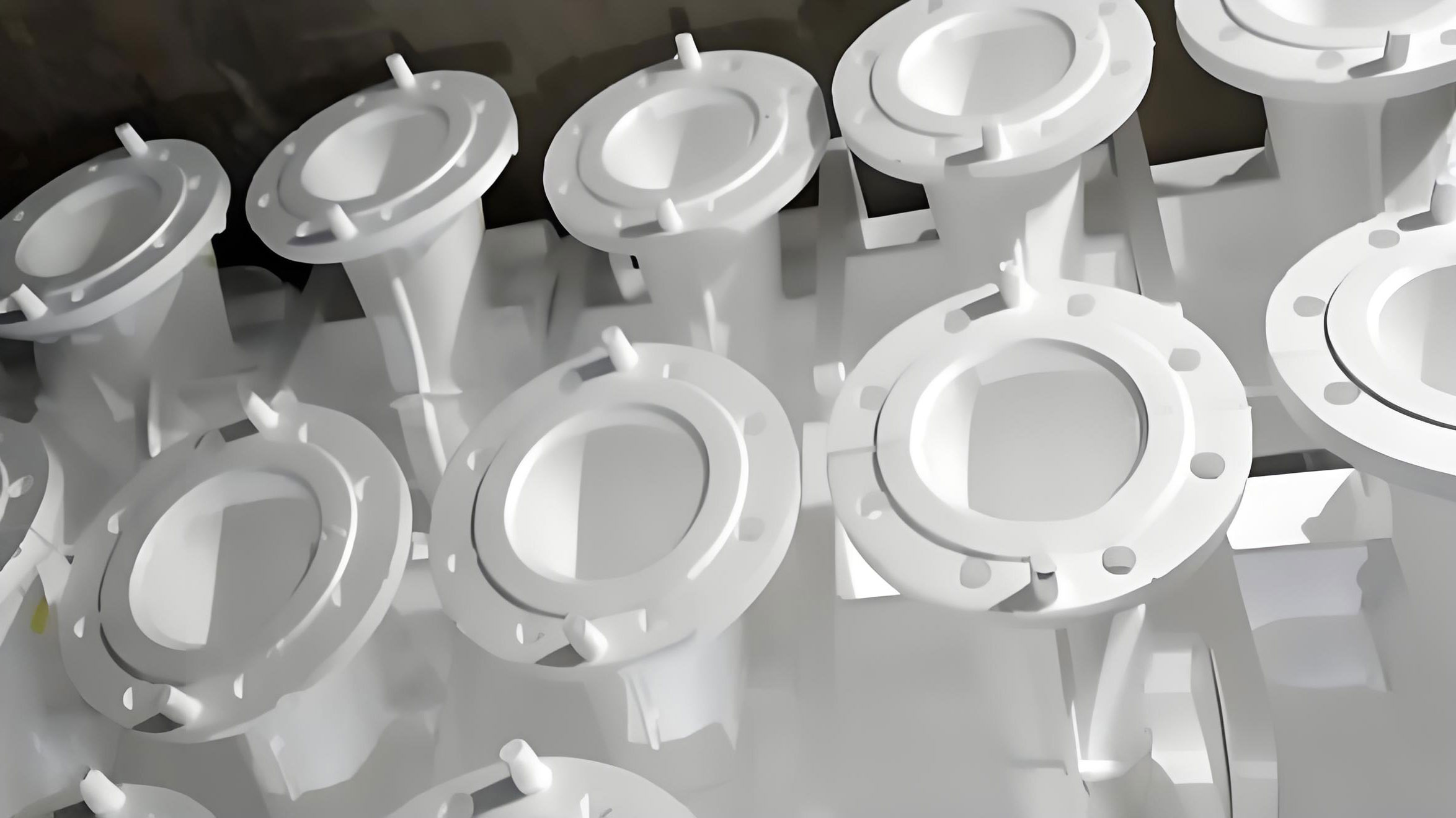
Overview of Preparation and Coating for Ductile Iron Pipe Fittings
Producing ductile iron pipe fittings via lost foam casting involves meticulous preparation of patterns and coatings to ensure defect-free castings. The process encompasses pattern coating, sand filling, and metallurgical control, each requiring precise execution based on the fitting’s geometry and material properties.
Coating Application and Composition
The coating applied to foam patterns in lost foam casting serves multiple purposes: it provides a barrier between the pattern and sand, enhances surface finish, and controls gas permeability. For ductile iron fittings, I typically use a water-based coating composed of ingredients like brown fused alumina, calcined bauxite, silica sol, surfactants, and defoamers. The coating formulation must balance viscosity and permeability, which can be quantified using the Darcy’s law for fluid flow:
$$ Q = \frac{k A \Delta P}{\mu L} $$
where \( Q \) is the flow rate, \( k \) is the permeability coefficient, \( A \) is the cross-sectional area, \( \Delta P \) is the pressure difference, \( \mu \) is the dynamic viscosity, and \( L \) is the coating thickness. The coating thickness \( L \) is critical and usually maintained around 1 mm after multiple layers. In practice, I apply at least three coats, with each layer dried at a controlled temperature (e.g., 50-80°C) to prevent moisture-related defects during pouring. The drying process removes water that could otherwise react with molten iron, causing gas porosity. The optimal thickness can be derived from empirical data, but a general rule is:
$$ L_{opt} = 0.5 + 0.1 \cdot d $$
where \( d \) is the fitting wall thickness in mm. For instance, a fitting with a 10 mm wall would require \( L_{opt} = 1.5 \) mm. The coating’s density \( \rho_c \) also affects performance; it should be around 1.8-2.0 g/cm³ to ensure adequate refractoriness without cracking.
Specific Molding of Pipe Fittings
Once coated, patterns are placed in flasks and surrounded by dry quartz sand. The sand filling and compaction process is vital to support the pattern and prevent mold collapse. For ductile iron pipe fittings, which often have intricate features like upper recesses and lower holes, vibration is used to achieve uniform sand density. The process involves:
- Placing a base layer of dry sand in the flask and vibrating for a set time (e.g., 30-60 seconds).
- Positioning the coated pattern and filling with more sand, followed by additional vibration to ensure tight packing.
- Applying a vacuum (negative pressure) during pouring and cooling to stabilize the mold and enhance metal flow.
The negative pressure \( P_v \) is typically maintained at 0.07 MPa for ductile iron, as it compensates for the expansion forces during solidification. Ductile iron exhibits a mushy solidification behavior due to graphite precipitation, which increases volume and can cause dimensional inaccuracies. The pressure required to counteract this expansion can be estimated using the Clausius-Clapeyron relation modified for casting:
$$ \Delta V = V_0 \beta \Delta T $$
where \( \Delta V \) is the volume change, \( V_0 \) is the initial volume, \( \beta \) is the volumetric expansion coefficient of ductile iron (approximately \( 1 \times 10^{-4} \, K^{-1} \)), and \( \Delta T \) is the temperature drop during solidification. The negative pressure helps contain this expansion, and the duration \( t_v \) of vacuum application depends on the fitting’s wall thickness. For medium-thickness fittings (e.g., 5-15 mm), I set \( t_v \) to about 4 minutes, calculated as:
$$ t_v = k_v \cdot w $$
where \( w \) is the wall thickness in mm and \( k_v \) is an empirical constant (around 0.3 min/mm). This prevents defects like swelling and ensures dimensional stability.
Melting and Metallurgy of Ductile Iron
The metallurgical preparation of ductile iron for lost foam casting is crucial to achieve the desired microstructure and mechanical properties. Based on composition requirements, I use a charge mix of pig iron, scrap steel, and returns, with pig iron dominating to ensure high carbon equivalent. The carbon equivalent \( CE \) for ductile iron is given by:
$$ CE = C + \frac{Si + P}{3} $$
where C, Si, and P are the percentages of carbon, silicon, and phosphorus, respectively. For pipe fittings, CE is typically maintained at 4.3-4.5 to promote graphite nodularization. The melting is conducted in induction furnaces, with tapping temperatures around 1500°C and pouring temperatures above 1400°C to ensure fluidity and proper mold filling.
Nodularization and inoculation are performed using the sandwich method, where 1% magnesium-based nodularizer and 1.5% ferrosilicon inoculant are added to the ladle. The reaction kinetics can be described by first-order kinetics for magnesium fade:
$$ [Mg]_t = [Mg]_0 e^{-kt} $$
where \( [Mg]_t \) is the magnesium content at time \( t \), \( [Mg]_0 \) is the initial content, and \( k \) is the decay rate constant. Rapid pouring after treatment is essential to retain magnesium effectiveness, preventing carburization issues in thin-walled sections. The resulting microstructure consists of ferrite and pearlite matrices with spheroidal graphite, meeting grade standards such as ISO 1083. Mechanical testing confirms tensile strengths exceeding 400 MPa and elongations over 12%, suitable for pressure pipe fittings.
To summarize the metallurgical parameters, I provide the following table for typical ductile iron compositions in lost foam casting:
| Element | Composition Range (wt.%) | Role in Ductile Iron |
|---|---|---|
| Carbon (C) | 3.6-3.9 | Promotes graphite formation and fluidity |
| Silicon (Si) | 2.0-2.5 | Enhances graphitization and strength |
| Manganese (Mn) | 0.1-0.3 | Controls pearlite formation |
| Magnesium (Mg) | 0.03-0.05 | Nodularizing agent for spheroidal graphite |
| Phosphorus (P) | < 0.05 | Minimized to avoid brittleness |
| Sulfur (S) | < 0.02 | Low to prevent interference with nodularization |
Application Status and Challenges of Lost Foam Casting in Domestic Production
In my assessment of the foundry industry, lost foam casting is primarily employed for complex-shaped components that are difficult to mold using traditional methods, such as ductile iron pipe fittings with intricate geometries. However, the adoption in domestic settings varies widely, with hundreds of facilities operating at different scales. These can be categorized into three types, as detailed below:
| Category | Description | Typical Capacity | Challenges |
|---|---|---|---|
| Domestic Closed-Loop Lines | Integrated systems with automated sand handling and recycling | Medium to high volume (100-1000 tons/year) | High initial investment and maintenance costs |
| 简易生产线 (Simple Lines) | Basic setups with manual operations and minimal automation | Low volume (<100 tons/year) | Inconsistent quality and low efficiency |
| Imported Advanced Lines | State-of-the-art equipment from international suppliers | High volume (>1000 tons/year) | High operational expertise required and dependency on foreign tech |
Despite the potential, many enterprises lack deep understanding of lost foam casting principles, leading to suboptimal implementation. The process has limitations, such as sensitivity to pattern quality and sand compaction, which not all castings are suitable for. The economic viability can be evaluated using a return on investment (ROI) formula:
$$ ROI = \frac{\text{Net Profit}}{\text{Investment Cost}} \times 100\% $$
where net profit accounts for reduced scrap rates and labor savings. For ductile iron pipe fittings, if scrap rates drop from 10% to 3% with lost foam casting, the ROI improves significantly. However, challenges persist, including the need for skilled technicians and R&D to optimize parameters like vacuum levels and coating formulations. From my experience, fostering technical talent and sharing best practices are urgent needs to accelerate the growth of lost foam casting in domestic markets. Continuous improvement in process control, perhaps using machine learning algorithms to predict defects, could revolutionize this field. The future looks promising if lessons from early adopters are heeded and innovation is pursued relentlessly.
In conclusion, lost foam casting presents a transformative approach for producing ductile iron pipe fittings, offering advantages in design flexibility, cost, and environmental impact. Through careful material selection, precise process control, and ongoing technical development, this technology can address the limitations of traditional methods. As I continue to explore its applications, I believe that with concerted efforts in research and training, lost foam casting will play a pivotal role in advancing the casting industry, particularly for complex components like pipe fittings. The integration of digital tools and sustainable practices will further enhance its viability, ensuring a bright future for this innovative casting method.