
In the manufacturing industry, the production of machine tool castings often involves large dimensions and high demands on surface quality and mechanical properties. Traditionally, furan resin sand casting has been widely adopted due to its maturity and stability. This process offers several advantages, such as high mold strength, excellent surface stability, and good thermal resistance, which minimize deformation during pouring. Additionally, the fluidity of the sand eliminates the need for vigorous compaction, reducing damage to patterns. However, furan resin sand casting has inherent drawbacks, including the emission of刺激性 odors, complex molding and assembly operations that require skilled labor, and difficulties in sand reclamation. These issues have driven the exploration of alternative methods, with lost foam casting emerging as a promising solution. The application of lost foam casting in machine tool components, particularly spindle boxes, has gained traction due to its environmental benefits, improved surface finish, dimensional accuracy, and reduced post-casting processing. This study delves into the practical implementation of lost foam casting for spindle box castings, focusing on process design, defect prevention, and overall efficiency.
The spindle box casting for a vertical machining center, with final machined dimensions of 910 mm × 650 mm × 520 mm and made of HT300 gray iron, represents a complex structure requiring high integrity. Key areas, such as the front bore for spindle installation and the top surface for motor mounting, must be free from defects and prohibit welding repairs. To adapt this component to lost foam casting, the initial step involved a thorough process analysis. Collaborating with designers, we modified the casting by adding six ϕ40 mm holes to facilitate sand flow and minimize the use of pre-filled resin sand, ensuring optimal vacuum distribution. The casting was oriented at a 30° angle with the spindle hole end facing upward and the slider mounting surface downward, with risers placed at the highest points to aid in feeding during pouring. This approach underscores the flexibility of lost foam casting in handling intricate geometries while maintaining quality.
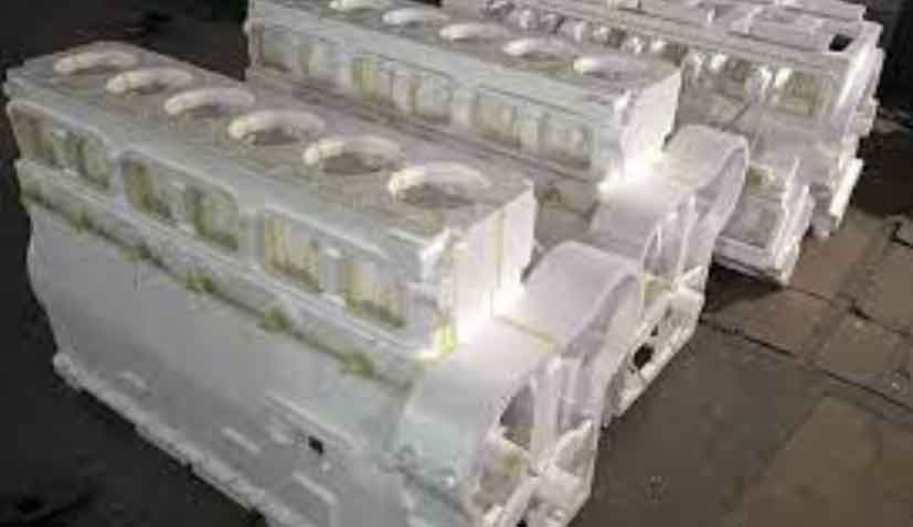
The lost foam casting process begins with pattern making, where expandable polystyrene (EPS) beads are used to create the foam pattern. After foaming, the pattern undergoes a controlled drying cycle to remove moisture and prevent defects. The drying process is critical and can be represented by a kinetic model for moisture evaporation: $$ \frac{dM}{dt} = -k (M – M_e) $$ where \( M \) is the moisture content, \( t \) is time, \( k \) is the drying rate constant, and \( M_e \) is the equilibrium moisture content. In our setup, the pattern is dried in stages: 25°C for 2 hours, 30°C for 2 hours, 35°C for 2 hours, and 40°C for 30 hours. This gradual increase ensures uniform drying without distortion. Once dried, the pattern, along with gating systems and risers, is assembled using adhesive, with seams sealed using masking tape to prevent coating infiltration. Reinforcement with fiber rods at critical points, such as the gating, enhances stability during subsequent steps.
Coating application is a vital phase in lost foam casting, as it provides a barrier between the foam pattern and the molding sand, ensuring surface quality. A specialized coating with a Baume degree of 70–75 is applied via dipping or spraying in three layers, each with a minimum thickness of 0.5 mm, resulting in a total coating thickness of at least 1.8 mm. The coating process involves multiple drying cycles to achieve proper adhesion and gas permeability. The drying kinetics can be described by an Arrhenius-type equation: $$ \tau = A e^{\frac{-E_a}{RT}} $$ where \( \tau \) is the drying time, \( A \) is a pre-exponential factor, \( E_a \) is the activation energy, \( R \) is the gas constant, and \( T \) is the temperature. Our drying regimen includes steps at 35°C for 2 hours, 40°C for 2 hours, 45°C for 2 hours, 50°C for 3 hours, and 55°C for 6 hours. This meticulous approach ensures that the coating is fully cured, reducing the risk of gas-related defects during pouring. The table below summarizes the coating parameters for clarity.
| Parameter | Value |
|---|---|
| Coating Baume Degree | 70–75 |
| Number of Layers | 3 |
| Minimum Layer Thickness | 0.5 mm |
| Total Coating Thickness | ≥1.8 mm |
| Drying Temperature Range | 35°C to 55°C |
| Total Drying Time | 15 hours |
Molding and sand filling in lost foam casting require precise control to ensure pattern integrity and proper compaction. The coated pattern is positioned in a flask, and sand is introduced while vibrating to achieve dense packing, especially in complex areas. The vacuum pressure, typically maintained at 0.06–0.07 MPa, plays a crucial role in stabilizing the mold during pouring. The sand filling efficiency can be modeled using a fluidization equation: $$ \frac{\partial \rho}{\partial t} + \nabla \cdot (\rho \mathbf{v}) = 0 $$ where \( \rho \) is the sand density and \( \mathbf{v} \) is the velocity vector. After sand filling, a plastic film covers the flask, and a pouring cup is installed. This setup ensures that the lost foam casting process proceeds smoothly, with the vacuum system extracting gases generated during foam decomposition.
Melting and pouring are critical stages that influence the final quality of lost foam castings. We employ a short-process method combining medium-frequency electric furnace melting with blast furnace iron, comprising 35% blast furnace iron, 45% scrap steel, and the remainder as returns of the same material. The chemical composition is tightly controlled, as shown in the table below, to meet HT300 specifications. Melting involves heating the iron to 1450°C for sampling, followed by升温 to 1520–1550°C for high-temperature holding for 8–10 minutes. This holding period refines the graphite structure, promotes deoxidation, and enhances inoculation effectiveness. The thermal dynamics during holding can be expressed as: $$ Q = m c_p \Delta T $$ where \( Q \) is the heat input, \( m \) is the mass of molten iron, \( c_p \) is the specific heat capacity, and \( \Delta T \) is the temperature change. After holding, the iron is tapped for temperature reduction, with inoculation using 0.4% silicon-barium-calcium inoculant in the ladle and 0.1% sulfur-oxygen inoculant during pouring. Pouring temperatures range from 1420°C to 1460°C, with vacuum maintained at 0.06–0.07 MPa and a holding time of 15 minutes to solidify the casting. This controlled approach in lost foam casting minimizes defects and ensures high yield.
| Element | Range |
|---|---|
| C | 3.1–3.2 |
| Si | 1.7–1.9 |
| Mn | 0.8–1.0 |
| S | 0.06–0.08 |
| P | ≤0.06 |
| Cr | ≤0.02 |
Defect prevention is paramount in lost foam casting to achieve high-quality castings. Common issues include collapse, burn-on/penetration, and gas holes/slag inclusions. Collapse often results from slow pouring rates or inadequate vacuum, leading to loss of mold integrity. To mitigate this, we ensure continuous pouring to keep the sprue sealed and design gating systems that promote uniform metal flow. The critical velocity for avoiding collapse can be estimated as: $$ v_c = \sqrt{\frac{2 g h}{\alpha}} $$ where \( v_c \) is the critical velocity, \( g \) is gravity, \( h \) is the metallostatic height, and \( \alpha \) is a flow factor. Burn-on and penetration occur due to thin coatings or high pouring temperatures; we address this by increasing coating thickness and using high-refractoriness coatings, with pre-filled resin sand in死角 areas. Gas holes and slag inclusions arise from foam decomposition products; optimizing pouring temperature and gating design helps evacuate gases and slag. The gas evolution rate during foam decomposition can be modeled as: $$ G = k_g e^{\frac{-E_g}{RT}} $$ where \( G \) is the gas generation rate, \( k_g \) is a constant, and \( E_g \) is the activation energy for decomposition. By implementing these measures, the defect rate in lost foam casting for spindle boxes is reduced to below 2%, achieving a qualification rate over 98%.
The successful application of lost foam casting in machine tool spindle boxes demonstrates its viability for complex, high-integrity castings. Compared to traditional methods, lost foam casting offers superior environmental conditions, reduced labor dependency, and lower post-casting workloads. Our experience shows that with proper process design, including pattern modification, controlled coating, and optimized pouring parameters, lost foam casting can produce castings free from defects in critical areas. The integration of mathematical models for drying, gas evolution, and fluid dynamics further enhances process control. As the industry moves towards greener manufacturing, lost foam casting is poised for continued growth, providing a sustainable solution for high-performance components. Future work could focus on automating pattern production and refining vacuum systems to push the boundaries of lost foam casting applications.