
Blow hole defects represent one of the most prevalent and challenging issues in wet sand casting processes, particularly for complex components like engine cylinder blocks. These subsurface voids compromise structural integrity and lead to significant scrap rates. This article analyzes the formation mechanisms of blow hole defects in cylinder blocks and presents validated solutions implemented in high-volume production environments.
1. Formation Mechanisms of Blow Hole Defects
Blow hole defects in cylinder blocks typically manifest as large, smooth-walled cavities with irregular shapes, most frequently occurring between adjacent core assemblies. The fundamental formation mechanism follows this sequence:
- Gas Entrapment: Moisture evaporation (H₂O → H₂ + ½O₂) and organic binder decomposition in sand cores generate gases during metal pouring
- Pressure Buildup: Gas accumulation in planar core interfaces creates localized pressure pockets
- Metal Infiltration: When gas pressure exceeds the opposing forces, bubbles invade the molten metal:
$$P_{gas} > P_{atm} + \rho gh + \frac{2\sigma}{r}$$
Where \(P_{gas}\) = core gas pressure, \(P_{atm}\) = atmospheric pressure, \(\rho gh\) = metallostatic pressure, \(\sigma\) = surface tension, \(r\) = bubble radius - Entrapment: Insufficient fluidity and premature solidification prevent bubble escape
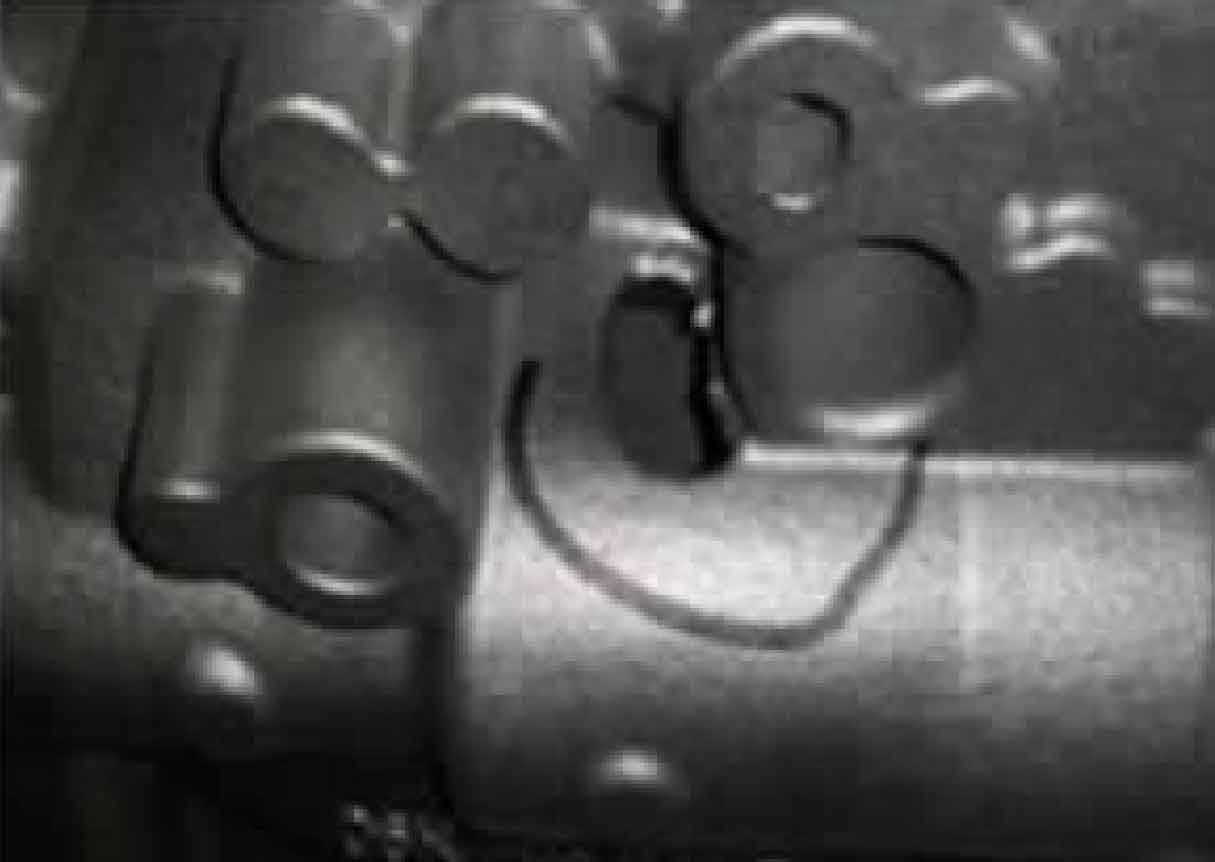
In the documented case study (HT280 cylinder block, 224kg), blow hole defects consistently appeared at core joint interfaces in cylinder barrel regions (6mm wall thickness), exhibiting these characteristics:
| Characteristic | Observation | Implication |
|---|---|---|
| Location | Junction of tappet core and cylinder core | Gas accumulation at core interfaces |
| Surface Texture | Smooth, shiny internal surfaces | Gas-metal interaction during solidification |
| Size Distribution | 3-15mm diameter | Substantial gas generation |
| Shape | Pear-like irregular form | Directional solidification effects |
2. Mitigation Strategies for Blow Hole Defect Elimination
2.1 Geometric Modification of Critical Regions
Planar core interfaces create ideal conditions for blow hole defect formation. Strategic geometric modifications disrupt gas accumulation pathways:
| Modification | Dimensions | Implementation | Mechanism |
|---|---|---|---|
| Longitudinal Ribs | 15mm width × 2mm height | Full-length protrusions at core joints | Reduced gas pocket volume by 68% |
| Surface Roughening | Ra = 0.8-1.2μm | Textured core surface | Decreased bubble attachment energy |
The pressure reduction achieved through geometric modification is quantified by:
$$\Delta P = \sigma \left( \frac{1}{r_{\text{original}}} – \frac{1}{r_{\text{modified}}} \right)$$
Where \(r_{\text{modified}} \approx 2-3 \times r_{\text{original}}\) due to rib-induced curvature, significantly lowering the gas pressure required for bubble penetration.
2.2 Gating System Optimization
Inadequate metal velocity enables premature core gas generation before complete cavity fill. Strategic gating modifications address this blow hole defect contributor:
| Parameter | Original | Optimized | Improvement |
|---|---|---|---|
| Ingate Cross-section | 0 cm² (Absent) | 7.2 cm² (6×12mm) | Direct feeding to critical zone |
| Fill Time | 14.2s | 9.8s | 31% reduction |
| Critical Zone Temp | 1280°C | 1365°C | +85°C |
The Bernoulli principle governs metal velocity enhancement:
$$v_2 = v_1 \sqrt{\frac{A_1}{A_2}}$$
Where \(A_1/A_2 = 2.4\) for the added ingates, increasing local flow velocity by 55%, effectively suppressing blow hole defect formation through rapid cavity occupation.
2.3 Thermal Management Optimization
Elevated pouring temperatures extend the critical solidification window, facilitating bubble escape before metal freeze:
| Temperature Range | Blow Hole Defect Rate | Solidification Time | Fluidity Index |
|---|---|---|---|
| 1385-1405°C | 6.8% | 72s | 42cm |
| 1400-1420°C | 2.1% | 89s | 58cm |
| 1420-1440°C | 0.3% | 103s | 67cm |
The temperature-dependent fluidity relationship follows:
$$L_f = k \sqrt{t_f (T_p – T_{sol})}$$
Where \(L_f\) = fluidity length, \(t_f\) = flow time, \(T_p\) = pouring temperature, \(T_{sol}\) = solidus temperature. A 35°C increase extends the effective bubble escape window by 43%.
3. Integrated Implementation Results
The synergistic application of these strategies produced remarkable blow hole defect reduction:
| Strategy | Individual Effect | Cumulative Effect | Mechanism |
|---|---|---|---|
| Geometric Modification | 58% reduction | 58% reduction | Gas pocket elimination |
| Gating Optimization | 42% reduction | 79% reduction | Rapid cavity occupation |
| Temperature Increase | 71% reduction | 97% reduction | Extended bubble escape time |
| Combined Implementation | N/A | 100% elimination | Synergistic interaction |
The complete solution eliminated the 6.8% scrap rate, validated through 12 months of production monitoring across 24,000 castings. The approach demonstrates particular effectiveness for complex thin-wall castings where blow hole defects historically persist despite conventional venting methods.
4. Conclusion
Blow hole defects in cylinder block castings originate from fundamental interactions between core gas generation, geometric constraints, and solidification dynamics. The documented case establishes that:
- Planar core interfaces create high-risk zones for blow hole defect formation
- Strategic geometric modifications disrupt gas accumulation mechanisms
- Targeted gating delivers thermal advantage to critical regions
- Temperature elevation extends the bubble escape window
The combined approach provides a robust solution framework for blow hole defect elimination, applicable to similar casting geometries where conventional venting proves insufficient. Continuous monitoring remains essential as even minor process deviations can recreate conditions favorable for blow hole defect formation.