
The lost foam casting process has established itself as a highly effective and versatile manufacturing technique for producing complex, near-net-shape castings from materials such as cast iron, aluminum, and copper alloys. While there have been successful reports of its application for steel grades like high-manganese steel and wear-resistant steel, its widespread adoption for general cast steel production, particularly low-carbon steels, has been relatively slower. A primary challenge limiting this expansion is the phenomenon of carbon pick-up or carburization. During the pouring and filling process, the advancing metal front interacts with the gaseous and liquid decomposition products of the vaporizing foam pattern. If these pyrolysis products are not efficiently evacuated from the mold cavity, they can lead to defects such as carburization, gas porosity, and hydrogen absorption, severely compromising the metallurgical quality and mechanical properties of the final casting.
This article delves into the intricate mechanisms behind carbon defect formation in lost foam cast steel and systematically outlines the fundamental principles and practical strategies for its prevention. A particular focus will be placed on advanced solutions like the use of ceramic gating systems, which represent a significant technological advancement in mitigating this persistent issue.
1. Fundamentals of Lost Foam Casting and Its Principles for Steel
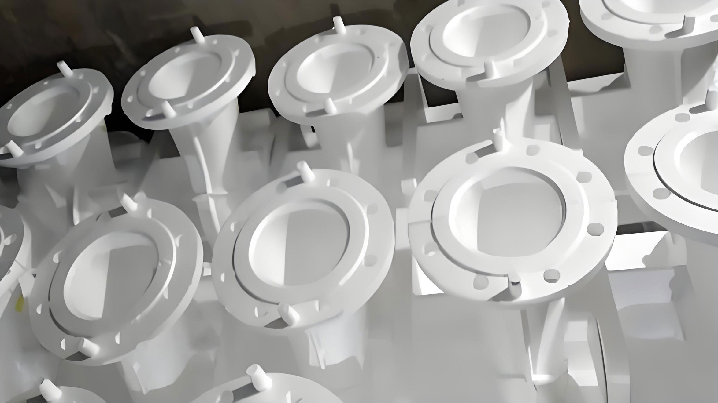
Lost foam casting, also known as evaporative pattern casting, involves creating a cluster of expandable polystyrene (EPS) or copolymer foam patterns that replicate the final part geometry. This cluster is coated with a refractory wash, dried, and then embedded in unbonded dry sand within a flask. The sand is compacted via vibration. Subsequently, molten metal is poured into the mold, causing the foam pattern to thermally degrade and vaporize, allowing the metal to occupy the pattern’s space and solidify into the casting.
For the successful production of sound steel castings using the lost foam process, three core principles must be rigorously adhered to:
- Creating High-Temperature, Oxygen-Deficient Conditions: The pattern must vanish primarily through gasification rather than combustion. Combustion in a localized oxygen-rich environment leads to soot (carbon) generation and its subsequent contact with the steel, causing severe localized carburization. A controlled, reducing atmosphere promotes cleaner pyrolysis.
- Balancing Metal Fill Velocity and Pattern Degradation Rate: The rate at which molten steel advances must be synchronized with the rate at which the foam pattern decomposes and its products are removed. Too slow a fill allows the metal front to cool excessively, while too fast a fill can trap liquid decomposition products. Elevated pouring temperature is often crucial to lower steel surface tension and viscosity, aiding in the displacement of residues and preventing defects like subsurface pinholes.
- Harnessing the Directed Nature of the Vacuum Field: The applied vacuum in the sand flask is not merely a uniform suction; it creates a directional flow field for the removal of pyrolysis gases. A complete loss of vacuum leads to mold collapse (run-out). A local loss can cause sand instability and inclusions. Understanding this directional aspect is vital for designing effective venting and gating to prevent defects such as sand penetration and non-fills.
2. Formation Mechanism of Carbon Defects in Lost Foam Cast Steel
Carbon pick-up in lost foam cast steel manifests as an increase in carbon content above the specified level for the alloy. This can occur as a surface carburized layer (0.1-3 mm deep with a carbon increase of 0.01-0.1 wt.%) or as a more uniform overall increase (0.01-0.05 wt.%). The susceptibility follows a clear trend: low-carbon steels (e.g., C < 0.25%) are most prone, medium-carbon steels (C 0.25-0.60%) less so, and high-carbon steels (C > 0.60%) show minimal issues. The uneven surface carburization leads to variable hardness and microstructures, degrading machinability, mechanical performance, and surface quality.
The root cause lies in the complex physicochemical reactions occurring at the metal-foam interface. The thermal decomposition of the foam pattern, typically EPS (polystyrene), is a multi-stage process. Upon heating, the long-chain polymer breaks down. A simplified representation of polystyrene decomposition is:
$$ (C_8H_8)_n \xrightarrow{\Delta} \text{Gases } (H_2, CH_4, C_2H_4, \text{ Styrene monomers}) + \text{Liquid intermediates (Tars)} + \text{Solid Carbon (Soot)} $$
At temperatures above approximately 800°C, further cracking of these primary products occurs, generating substantial amounts of hydrogen and fine carbon black (soot). The fate of this carbon determines the defect severity.
The pathways for carbon defect formation are two-fold:
- Direct Carbon Transfer: The carbon black (soot) generated from secondary cracking is a direct source of elemental carbon. Under the influence of the vacuum, a significant portion is drawn through the permeable coating into the sand. However, a fraction remains adsorbed on the inner coating surface or is suspended at the metal front.
- Reaction with Liquid Pyrolysates: The liquid tarry residues, which are rich in carbon, can be entrapped between the advancing metal and the coating. At the high temperatures of molten steel (>1550°C), these residues can decompose or directly diffuse carbon into the steel surface, especially where the metal flow is turbulent or stagnant.
The overall carbon mass transfer can be conceptually modeled by considering the concentration gradient and the contact time. The carbon flux \( J_C \) into the steel surface can be approximated by:
$$ J_C \propto D_C \cdot \frac{\partial C}{\partial x} \cdot t_c $$
where \( D_C \) is the carbon diffusion coefficient in the steel at the interface temperature, \( \frac{\partial C}{\partial x} \) is the carbon concentration gradient between the pyrolysis products and the steel, and \( t_c \) is the effective contact time. In lost foam casting, \( t_c \) is heavily influenced by the gas evacuation rate and metal flow dynamics.
3. Comprehensive Strategies for Preventing Carbon Pick-up
Preventing carburization in lost foam cast steel requires a holistic approach, addressing every stage of the process chain. No single parameter adjustment is sufficient; a synergistic combination of the following measures is essential.
3.1. Pattern Material Selection and Density Control
The choice of foam material is the first and most critical step in controlling the carbon source. The inherent carbon content and decomposition behavior vary significantly.
| Material | Chemical Formula | Key Characteristics | Effect on Carbon Defect |
|---|---|---|---|
| EPS (Expanded Polystyrene) | (C8H8)n | Low cost, high carbon/hydrogen ratio, produces significant liquid tar and soot. | High risk. Prone to severe carburization and carbon folds. |
| PMMA (Polymethyl Methacrylate) | (C5H8O2)n | Lower carbon content, gasifies more cleanly with less residue. | Lower carbon risk, but higher total gas volume can cause other defects. |
| STMMA (Styrene-Methyl Methacrylate Copolymer) | Copolymer | Balances properties: lower carbon than EPS, lower gas volume than PMMA. | Recommended. Optimal compromise, significantly reduces carbon pick-up. |
Furthermore, the pattern density must be minimized while maintaining adequate handling strength. A lower density directly reduces the mass of carbon introduced into the system. For critical steel castings, using STMMA or similar copolymers with a density controlled between 0.018-0.022 g/cm³ is a best practice.
3.2. Optimized Casting Process Design
The gating and feeding system design must prioritize the rapid and smooth removal of decomposition products. Key guidelines include:
- Gating Orientation: Prefer top gating or step gating for parts that are not excessively tall. This creates a thermal gradient that helps push pyrolysis products upward ahead of the rising metal.
- Gating Distribution: For large or tall castings, use multiple, well-distributed ingates to avoid localized over-concentration of pyrolysis products. The sprue system should be designed to ensure a non-turbulent, laminar fill as much as possible.
- Use of Blind Risers and Slag Traps: Employing blind risers (feeder heads) is common. Additionally, small slag collector risers or carbon traps can be placed at the highest points or in areas prone to defect accumulation. These act as reservoirs to collect the metal front laden with liquid pyrolysis residues and carbon.
3.3. Coating Formulation and Application
The refractory coating is the barrier and filter between the degrading foam and the sand. Its properties are paramount.
- High Permeability: The coating must have excellent gas permeability to allow the rapid egress of pyrolysis gases. This reduces the partial pressure and residence time of carbon-bearing species at the metal interface.
- Controlled Thickness: While providing necessary refractoriness, the coating should be as thin as practically possible. A thinner coating dramatically increases its overall permeability. A typical target is 0.3-0.8 mm after drying.
- Catalytic Additives: Research indicates that incorporating small amounts of additives like cryolite (Na3AlF6) can be beneficial. At high temperatures, cryolite decomposes and its products may catalyze the further breakdown of tarry residues and adsorb carbon species, helping to clean the metal front.
3.4. Process Parameter Control: Vacuum, Temperature, and Pouring Speed
These three interactive parameters form the core of the process window for lost foam casting of steel.
| Parameter | Recommended Range for Steel | Rationale and Effect |
|---|---|---|
| Vacuum Level | 0.03 – 0.05 MPa (230 – 380 mmHg) | Sufficient to stabilize the mold, evacuate gases rapidly, and reduce pyrolysis product concentration. Excessive vacuum can increase metal velocity and turbulence, entrapping liquids. |
| Pouring Temperature | ~40-80°C above conventional sand casting (e.g., >1420°C for low-carbon steel castings) | Higher superheat improves metal fluidity, aids in displacing residues, and promotes more complete pattern gasification. It lowers the metal’s surface tension, helping bubbles detach. |
| Pouring Speed / Time | Optimized for “balance”: Fast enough to prevent mistun, slow enough to prevent turbulence. | The speed must be synchronized with the pattern degradation rate. An optimal speed creates a stable, slight gap between the metal and the foam, allowing gases to escape. |
The relationship can be conceptualized by a process window equation aiming to minimize the contact time \( t_c \):
$$ t_c \approx \frac{L}{v_m} – \frac{\delta}{v_g} $$
where \( L \) is a characteristic length of the cavity, \( v_m \) is the metal front velocity, \( \delta \) is the gas film thickness, and \( v_g \) is the gas evacuation velocity (enhanced by vacuum and coating permeability). The goal is to maximize \( v_g \) and optimize \( v_m \) to make \( t_c \) as small as possible.
3.5. Structural Modifications and Machining Allowances
When possible, part design should be modified for the lost foam process. Thick sections can be cored out to create hollow structures, reducing the volume of foam to be decomposed locally and minimizing hot spots where carbon defects are likely. For unavoidable critical areas prone to slight carburization, increasing the machining allowance ensures the affected layer is completely removed during finishing.
4. The Revolutionary Role of Ceramic Gating Systems
One of the most effective technological innovations for combating carbon pick-up in lost foam cast steel is the replacement of foam gating channels with pre-formed refractory ceramic tubes and components. This approach directly attacks the problem at its source by eliminating a significant portion of the decomposable pattern material from the system.
4.1. Advantages of Ceramic Sprue Tubes and Runners
By using ceramic gating systems, the following benefits are realized:
- Dramatic Reduction in Carbon Source: The sprue, runners, and sometimes even the ingates are no longer made of foam. This removes a substantial mass of carbonaceous material that would otherwise need to be decomposed during pour. The carbon potential in the cavity is significantly lowered.
- Elimination of Gating-Related Carbon Defects: Carbon folds, slag, and soot originating from the burning of foam gating channels are virtually eliminated. The metal enters the mold cavity cleaner.
- Improved Thermal and Erosion Resistance: High-quality, thick-walled ceramic tubes possess high hot strength and low thermal expansivity. They resist metal erosion (washing) better than a sand coating over foam, preventing sand inclusions and improving gating dimensional stability, which leads to more predictable feeding.
- Process Simplification and Cost Reduction: There is no need to coat the ceramic gating system with refractory wash, saving labor and material. The need for flow-off bricks or special coatings in the sprue base is also reduced. The system provides a smooth, consistent flow channel.
4.2. Application and Integration
In practice, the ceramic sprue and runner tubes are assembled externally to the foam pattern cluster using high-temperature adhesives or locking mechanisms. This assembly is then coated along with the foam pattern sections. The ingates can be formed using foam (with careful design) or, more effectively, by using specially designed flat ceramic blades or blocks that define the gate geometry. These ceramic components ensure a clean, carbon-free transfer of metal from the pouring cup to the mold cavity.
This method synergizes perfectly with the use of advanced feeding systems. Exothermic insulating riser sleeves can be placed directly on the casting. Their function is dual: they provide excellent thermal insulation to maintain a long-lasting liquid feed reservoir for solidification shrinkage, and they also act as excellent sinks for any remaining floating oxides or carbonaceous materials that may have entered the cavity, further cleansing the casting.
4.3. Complementary Innovative Processes
For the most carbon-sensitive alloys, such as specific low-carbon and stainless steels, even more advanced hybrid techniques have been developed:
- Precision Composite Casting (Foam Pattern + Investment Shell): A high-density foam pattern is invested with a ceramic shell (like in investment casting). After the shell is hardened and dried, the foam is removed, and the empty ceramic shell is placed in a sand flask under vacuum for pouring. This completely decouples the metal from any foam decomposition products.
- “Burn-Out” or “Empty Mold” Casting: The foam pattern cluster is intentionally ignited and burned out in a controlled manner inside the mold before pouring, leaving an empty cavity. This eliminates all organic material but requires careful control of burnout and mold atmosphere to avoid other defects.
- High-Vacuum Top Gating with Large Risers: Some specialized approaches utilize very high vacuum levels combined with top gating through large risers that act as the primary fill path. This promotes rapid, oxygen-assisted combustion and evacuation of the pattern, minimizing residual carbon contact time.
5. Conclusion
The issue of carbon pick-up in lost foam cast steel is a multifaceted challenge rooted in the fundamental interaction between molten steel and the decomposing foam pattern. Success in producing high-integrity steel castings via the lost foam casting process hinges on a systems-engineering approach. It requires careful selection of low-carbon pattern materials like STMMA, precise control of process parameters (vacuum, temperature, pouring speed), the design of gating systems that promote clean filling, and the application of highly permeable coatings.
Among these strategies, the adoption of ceramic gating systems stands out as a particularly powerful and direct method for mitigating carburization. By removing the organic material from the gating channels, it significantly reduces the carbon load in the system, leading to cleaner metal entry and higher quality castings. As lost foam casting technology continues to evolve, the integration of such innovative solutions with robust process control will be key to unlocking its full potential for an ever-broader range of demanding steel casting applications, ensuring the benefits of design flexibility and cost-effectiveness are realized without compromise to metallurgical quality.