
As a practitioner deeply involved in the field of lost foam casting (LFC), I have observed firsthand the significant challenges posed by various casting defects in the production of complex thin-walled components. The transition of this technology from prototyping to high-volume manufacturing necessitates a rigorous, principle-driven approach to process control. Based on extensive experience, particularly with intricate parts like transmission housings, this article delves into a detailed first-person analysis of common casting defects, their root causes, and the systematic engineering solutions developed to mitigate them. The interplay of foam properties, coating technology, sand dynamics, and thermal management creates a complex system where a change in one parameter can influence multiple defect mechanisms. Understanding these relationships is key to achieving robust production.
The component in focus is a thin-walled transmission housing with a major wall thickness of 6 mm and overall dimensions of approximately 410 mm x 310 mm x 320 mm, cast in HT250 grey iron. Its structure is discontinuous with significant internal cavities, making it inherently prone to distortion and filling-related issues. Initial production attempts were plagued by high scrap rates, primarily due to a cluster of interrelated casting defects: distortion, slag inclusions (a unique LFC defect often called “carbonaceous defects” or “lustrous carbon films”), sand penetration/burning-on (referred to as “iron-wrapped sand”), and cold shuts. The following sections provide a comprehensive breakdown of each defect family.
1. Distortion Defect: Analysis and Containment
Distortion in the context of LFC refers to the dimensional deviation of the final metal casting that originates from the deformation of the expendable foam pattern before metal pour. This pattern distortion is a critical failure mode distinct from casting shrinkage or warpage.
1.1 Root Cause Analysis
The foam pattern, typically made of Expanded Polystyrene (EPS), has a low elastic modulus and yield strength. During two critical pre-pour operations—coating immersion and sand compaction via vibration—the pattern is subjected to asymmetrical forces. The liquid coating applies hydrostatic pressure and viscous drag forces, while the flowing and compacting sand grains apply point-specific frictional and normal stresses. For a thin-walled, open-box structure like a transmission housing, these forces can easily exceed the foam’s structural resistance, especially across unsupported spans. The resulting plastic deformation of the pattern is then replicated exactly in the final metal casting. The scrap rate from this defect alone initially exceeded 15%.
The mechanical principle can be simplified as a foam beam under a complex, non-uniform load. The deflection $ \delta $ can be conceptually related to the applied pressure (from coating and sand, $P$), the unsupported length $L$, and the foam’s flexural modulus $E_f$ and moment of inertia $I$ (which is a function of wall geometry). While not a perfect classical beam, the relationship highlights key factors:
$$ \delta \propto \frac{P \cdot L^n}{E_f \cdot I} $$
where $n$ is a factor accounting for the load distribution. This shows that reducing unsupported length ($L$) is the most direct lever to control deflection $ \delta $.
1.2 Mitigation Strategy: Strategic Support Ribs
The solution emerged from the principle of force balancing. The goal was to introduce internal reaction forces to counteract the external loads from coating and sand. This was achieved by gluing temporary foam support ribs across the major internal openings of the pattern. These ribs, which are removed from the pattern cluster after coating and before sand filling, act as internal struts. They dramatically increase the effective moment of inertia $I$ of the structure and reduce the unsupported span $L$ during the vulnerable process stages.
The design of these ribs is crucial. They must be:
- Sufficiently rigid to provide support.
- Easy to remove without damaging the coated pattern.
- Placed strategically to bisect the largest unsupported panels.
This intervention successfully balanced the asymmetric forces, reducing distortion-related scrap to negligible levels. It is a perfect example of addressing a casting defect by stabilizing its precursor (the pattern) in the process chain.
2. Slag Inclusions (Carbonaceous Defects): A Signature LFC Challenge
Slag inclusions here are not merely refractory slags from ladle linings. In LFC, they primarily originate from the pyrolysis products of the foam pattern itself. This category of casting defects was the most prevalent initially, accounting for up to 25% scrap.
2.1 Mechanism of Formation
When molten metal replaces the foam pattern, the EPS undergoes rapid thermal degradation. This complex process occurs in several stages, progressing through the foam thickness ahead of the advancing metal front:
- Glass Transition & Melting: EPS softens (Tg ~100°C) and melts.
- Depolymerization: Long-chain polymers crack into shorter chains and styrene monomers (starting around 300°C).
- Vaporization & Further Cracking: Liquids vaporize, and hydrocarbons crack into smaller gaseous molecules (H2, CH4, C2H4, etc.) and a tarry liquid residue.
- Carbon Formation: In oxygen-deficient conditions (behind the coating), the tarry residue further cracks into solid pyrolytic carbon (lustrous carbon) and more gases.
The two primary sources of defect formation are:
- Internal Entrapment: If the gaseous and liquid pyrolysis products cannot escape quickly enough through the coating and sand, they may be trapped by the advancing metal front. The liquid tar and solid carbon can then be incorporated into the metal as black, shiny, often flake-like inclusions.
- Coating Erosion & Entrainment: High-velocity metal flow can mechanically erode the coating, especially at sharp corners or rough surfaces. The dislodged coating fragments become exogenous inclusions.
The defect appears as black, irregular patches on the casting surface or within the wall upon machining.
2.2 Mitigation Through Integrated Process Control
Combating this defect requires a multi-pronged strategy that balances the rate of gas generation with the rate of gas removal, while minimizing coating erosion.
| Control Parameter | Target/Strategy | Effect on Pyrolysis Products | Effect on Removal Rate | Risk of Inducing Other Defects |
|---|---|---|---|---|
| Foam Density | Optimized (23-25 g/L) | Reduces mass of carbon-forming material per volume. | Minimal direct effect. | Too low: poor surface finish, coating penetration. Too high: excessive gas. |
| Gating System Design | Hollow, cylindrical, molded sprue | Minimizes foam volume in gating. | Promotes rapid, tranquil fill; reduces coating erosion. | Poor design can cause turbulence, increasing slag and cold shuts. |
| Coating Permeability | High enough for venting | No direct effect. | Increases gas evacuation rate. | Excessive permeability promotes metal penetration (burn-on). |
| Sand Permeability & Vacuum | Adequate compaction & vacuum level | No direct effect. | Vacuum enhances gas extraction through coating/sand. | Excessive vacuum can cause mold collapse or penetration. |
| Pouring Temperature | Sufficiently high (≥1480°C) | Increases cracking to gaseous products vs. tars. | Higher metal fluidity may aid floating of inclusions. | Can exacerbate penetration and shrinkage porosity. |
2.2.1 Optimized Foam Density: A critical trade-off exists. While lower foam density reduces the mass of carbonaceous residue, it compromises surface quality and makes the foam more susceptible to coating liquid penetration, which can create a different type of inclusion. Through systematic trials, a pre-expanded bead density range of 23-25 g/L was identified as optimal for this 6mm wall casting, balancing low gas generation with good pattern surface integrity.
2.2.2 Redesigned Gating System: The original gating, hand-cut from low-density foam board, was a significant contributor. Its rough surface and sharp corners promoted coating erosion and turbulence. It was also solid, representing excess foam to decompose.
The redesign focused on three principles:
- Molded for Smoothness: Using a mold ensured a smooth, sealed surface, minimizing coating penetration points.
- Cylindrical Shape: A ∅36 mm cylinder presents the smallest surface area for a given cross-section, reducing friction and erosion.
- Hollow Core: A central ∅20 mm void drastically reduces the total foam mass in the sprue, lowering the gas load. It also allows metal to initially flow through a pre-existing channel, reducing temperature loss and initial back-pressure.
The improvement was substantial: reduced turbulence, higher effective pouring temperature, less gas generation, and a significant drop in slag-related casting defects.
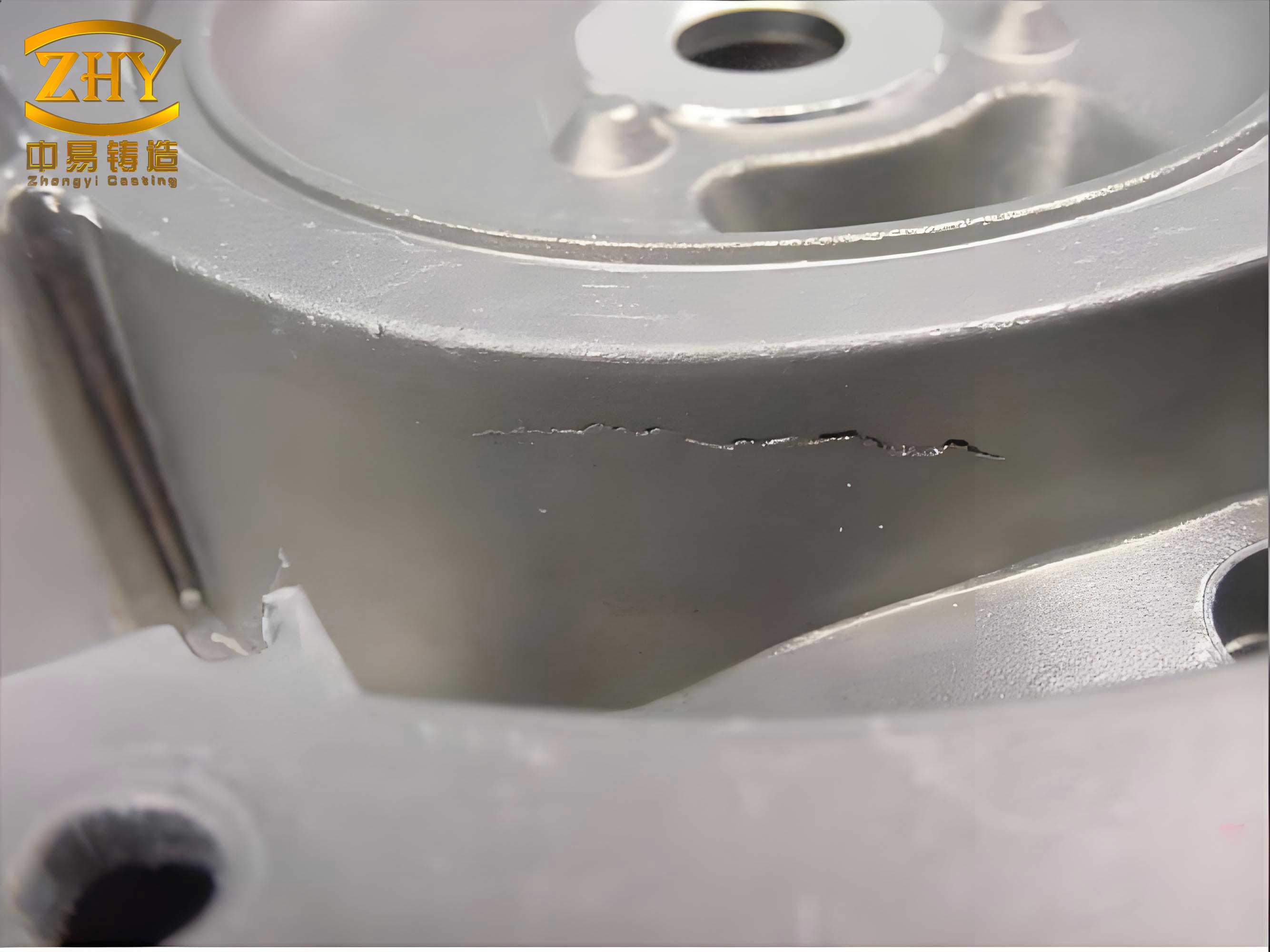
The image above illustrates the complex morphology of various internal and surface casting defects, akin to the challenges faced in LFC, highlighting the importance of defect analysis.
3. Sand Penetration / Burning-On (“Iron-Wrapped Sand”)
This defect manifests as a rough metal surface with fused sand grains that are mechanically inseparable. It is fundamentally a failure of the refractory coating under the combined thermo-mechanical assault of the molten metal.
3.1 Root Cause: Sand Bed Stability in Complex Geometries
In areas with deep pockets, overhangs, or acute internal angles—common in a transmission housing—achieving uniform and high sand compaction is challenging. During vibration, sand may “bridge” across an opening, leaving a void or a low-density zone beneath it. When the coating layer is not uniformly supported by dense sand, the dynamic pressure of the molten metal ($P_{metal}$) during pouring can exceed the coating’s hot strength, causing it to fracture or rupture.
The metal pressure at a given depth $h$ is given by: $$ P_{metal} = \rho_{metal} \cdot g \cdot h $$ where $\rho_{metal}$ is the metal density and $g$ is gravity. If the local sand compaction is low, its resisting force $F_{sand}$ is reduced. Failure occurs when:
$$ P_{metal} > \frac{(S_{coating} + F_{sand})}{A} $$
where $S_{coating}$ is the coating’s strength and $A$ is the area. The unsupported coating is the weak link.
3.2 Mitigation: Enhanced Sand Compaction Strategy
The solution involved a two-stage sand filling and vibration protocol tailored to complex geometries:
- Base Sand & Initial Vibration: A layer of base sand is laid and compacted to create a firm foundation.
- Pattern Placement & Stage 1 Fill: The pattern is placed, and sand is filled manually with active assistance (using tools to guide sand) into all recesses and cavities until level with the pattern’s top. This step, before major vibration, ensures sand physically occupies difficult areas.
- Stage 1 Vibration: The flask is vibrated with parameters optimized to densify this sand without causing segregation or re-fluidization. Parameters were fine-tuned to an acceleration of $1.0g-1.5g$ ($9.8-14.7 m/s^2$) and a frequency of 45-50 Hz for a duration of ~20 seconds. This compacts the sand in the critical cavities.
- Stage 2 Fill & Vibration: The flask is topped up with cover sand and given a final, shorter vibration to compact the upper layers, ensuring overall mold rigidity and adequate sand pressure on upper surfaces of the pattern.
This method ensures high and uniform sand density $(\rho_{sand})$ throughout, maximizing $F_{sand}$ and providing uniform support to the coating, thereby eliminating the casting defect of sand penetration.
4. Cold Shut Defect
Cold shuts appear as a line or seam on the casting where two streams of metal met but failed to fuse completely, often due to insufficient thermal energy.
4.1 Analysis: Thermal Deficit in Thin Sections
For thin-walled castings, the high surface-area-to-volume ratio leads to rapid heat loss. As the metal front advances through the narrow, foam-filled cavity, it loses heat to:
- Heating and decomposing the foam (endothermic reaction).
- Heating the coating and the sand mold.
- Radiation and convection from the metal surface itself.
If the temperature at the flow front drops below the liquidus temperature or if the oxide film on the front becomes too stable, fusion will not occur when two fronts meet, resulting in a cold shut. This is governed by the heat balance at the flow front. The temperature drop $\Delta T$ over a flow distance $x$ can be approximated by considering the heat sink of the foam:
$$ \Delta T \approx \frac{ \dot{q}_{foam} \cdot x }{ v \cdot \rho_{metal} \cdot C_p } $$
where $\dot{q}_{foam}$ is the heat flux into the foam per unit length (a function of foam density and decomposition enthalpy), $v$ is the flow velocity, and $C_p$ is the metal’s specific heat. Low $v$ and high $\dot{q}_{foam}$ lead to large $\Delta T$.
4.2 Mitigation: Boosting Thermal Head
The primary countermeasure is to increase the initial thermal head to compensate for the inevitable losses.
- Increased Pouring Temperature: The furnace tap temperature was raised to 1560°C, with a strict minimum pour temperature of 1480°C. This provides a larger “thermal budget” for the metal to survive the endothermic foam decomposition and mold heating without dropping below the critical fusion temperature.
- Enhanced Flow Velocity: The redesigned gating system (hollow sprue) also contributes indirectly by reducing flow resistance and potentially increasing $v$, thereby reducing the time for heat loss over a given distance.
This direct thermal management approach proved highly effective in eliminating cold shuts, another critical class of filling-related casting defects.
5. Synthesis and Process Interrelationships
The successful mitigation of these casting defects was not achieved by treating them in isolation. The lost foam process is a tightly coupled system. For instance, increasing pouring temperature helps with cold shuts and slag inclusion reduction but aggravates the risk of sand penetration. Increasing vacuum improves slag removal but can lead to mold collapse. Therefore, the final process is a finely tuned equilibrium.
| Defect | Primary Control Knob | Optimal Setting for Transmission Housing | Positive Side Effect on Other Defects | Negative Side Effect (to be managed) |
|---|---|---|---|---|
| Distortion | Mechanical Support (Ribs) | Temporary foam support ribs | None direct | Added pattern assembly step. |
| Slag Inclusions | Foam Density & Gating | Density: 23-25 g/L; Hollow cylindrical sprue | Smoother fill aids cold shut prevention. | Must ensure coating adhesion on smooth sprue. |
| Sand Penetration | Sand Compaction Strategy | 2-stage manual assist + vibration (45-50 Hz, ~20s) | Uniform mold strength supports high pour temp. | Over-vibration can cause pattern deformation (mitigated by ribs). |
| Cold Shut | Thermal Head (Pour Temp) | Pour Temp ≥ 1480°C | Improves fluidity, helps flush inclusions. | Increases thermal load on coating/sand. |
| Overall Enabler | Robust, high-permeability coating that can withstand high temperature while allowing rapid gas evacuation. This is the critical interface that makes the other optimizations possible. | |||
The conclusions drawn from this extensive problem-solving journey are fundamental to controlling casting defects in lost foam production of complex thin-wall castings:
- Pattern Integrity is Paramount: Mechanical stabilization of the foam pattern using temporary support ribs is a cost-effective and essential step to prevent distortion, a precursor defect.
- Foam Quality and Gating are Key to Gas Management: An optimized, molded foam density (~23-25 g/L) coupled with a streamlined, hollow gating system minimizes the generation and entrapment of pyrolysis products, directly attacking the core mechanism of LFC-specific slag inclusions.
- Sand Dynamics Must be Actively Managed: Uniform and high sand compaction, achieved through a geometry-aware, multi-stage filling and vibration process, is non-negotiable for preventing sand penetration/burning-on defects, especially in complex cores and cavities.
- Thermal Energy is the Currency of Filling: Maintaining a sufficiently high pouring temperature (>1480°C) is the primary defense against cold shuts in thin sections, compensating for the significant endothermic heat sink of the decomposing foam.
The systematic application of these principles, with an understanding of their interactions, transformed the production of the transmission housing from a high-scrap endeavor to a reliable, controlled process. This framework for analyzing and mitigating casting defects—addressing the pattern, the gas, the mold, and the heat in an integrated manner—provides a robust template for tackling challenges in lost foam casting across a wide range of components.
Future work continues to focus on predictive modeling of foam degradation, advanced coatings with graded permeability, and real-time process control to further minimize the occurrence of these casting defects, pushing the quality and capability of lost foam casting to new frontiers.