
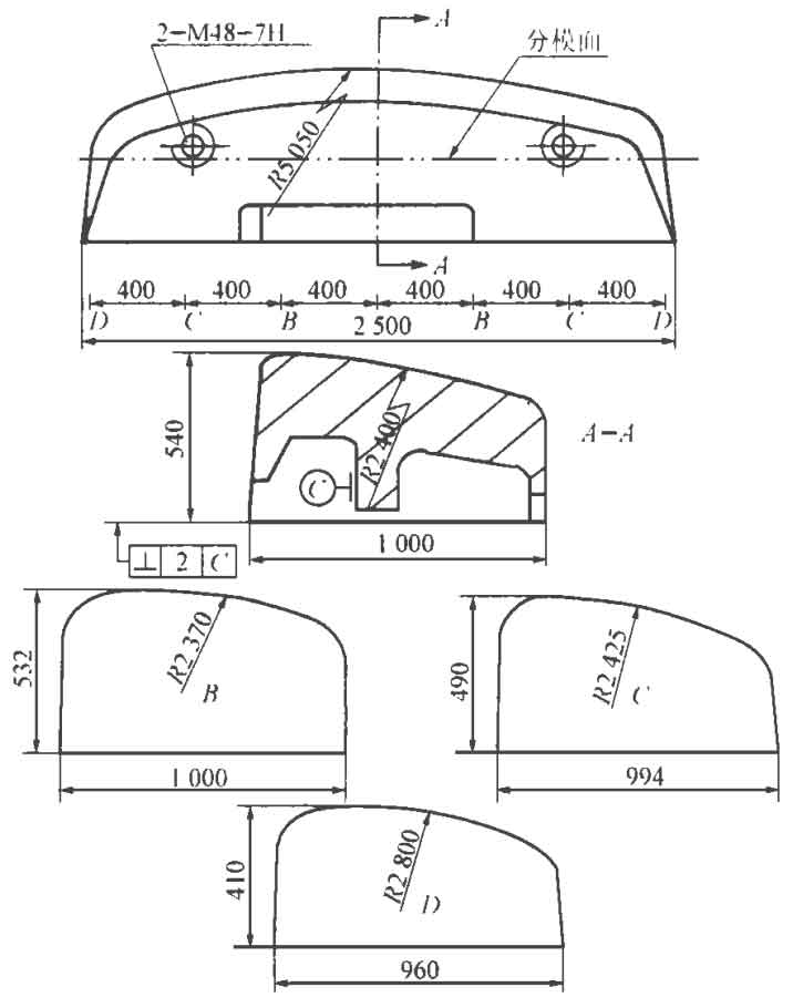
The counterweight iron material is HT100, and the structure is shown in Figure 1. It is a “bread” shape, on which is a combined curved surface composed of many circular arcs The C surface of the bottom surface and inner cavity is the installation surface, and the physical position tolerance is required, and the other surfaces are the appearance surface. The part has the following characteristics: ① the overall dimension of the part is large and the mass is 6T. ② The wall thickness of the casting varies greatly, 455mm at the thickest part and 30mm at the thinnest part. ③ The machining surface of the parts is less, the casting requirements are high, especially the appearance quality requirements are higher, and several embedded screw holes have high position accuracy. ④ The shape of the parts is complex, but the casting process is good. It can directly start the mold without core box, etc.
1. Casting model
As the casting has good processability, it is proposed to use the upper and lower sand boxes to directly lift the mold. As a counterweight iron, its appearance quality is an important technical requirement. Therefore, the arc surface of the part is downward, and the whole part is cast in the bottom box. In this way, the arc surface is poured first, and there will be no dislocation of parting surface on the part. Due to the high parts and the lack of a suitable position to hit the model, it is difficult to lift the mold, so the whole model is divided into two types. The double dotted line in Figure 1 is used as the parting surface, and the upper and lower molds are positioned by positioning pins and connected with bolts, which can be opened and closed.
2. Casting molding
The modeling process is as follows:
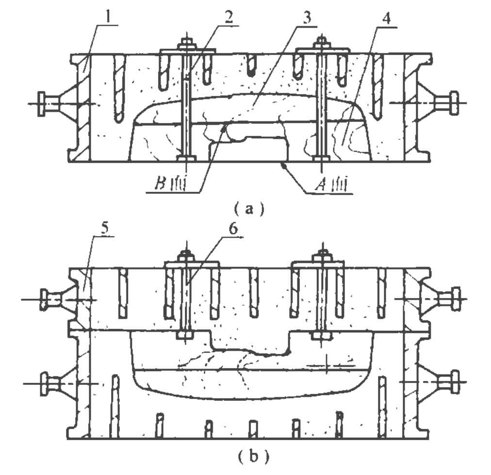
(1) As shown in Fig. 2 (a), the a of the lower mold 4 is placed horizontally downward, the lower sand box 1 is buckled on the model, the upper and lower models share the screw 2 to be hung on the lower box belt, and then sand is filled and tamped from the bottom of the lower box.
(2) After tamping, turn the lower box over 180 °, loosen bolt 2, and hit the surface a of the lower mold to properly separate the mold from the sand mold.
(3) As shown in Fig. 2 (b), put on the upper box 5, connect the lower mold 4 with the upper box 5 with screw 6, and then fill sand for tamping.
(4) After tamping, lift the upper box slowly, and at the same time, lift the lower formwork 4 together with the upper box.
(5) Turn over the upper box 180 °, loosen the bolt 6, lean against the parting surface B, and then lift the lower mold 4 to separate from the upper box.
(6) Knock down the surface 3b of the upper die in the box and pull out the upper die.
(7) Trim the cavity. Carefully flatten the possible unevenness of the mold surface on the parting surface of the lower box. At the same time, in order to improve the surface quality of the casting, the mold cavity is coated with graphite powder instead of graphite powder. The clay dry sand mold is adopted, and the hardness of the sand mold reaches 90. Therefore, the upper and lower sand molds shall be closed after drying.
3. Casting, feeding and others
Since the weight of parts exceeds the tonnage of the existing cupola and the capacity of molten iron ladle, two 3 ∙ 5T molten iron ladle are used for pouring from both ends. After the cupola melts the first ladle of molten iron, it shall be subject to thermal insulation treatment. After the second ladle of molten iron is melted, it shall be poured from J1 and J2 gates at the same time. The two-layer ladder gating system is adopted, and the upper layer is located on the parting surface. Each layer is provided with two inner gates with a section of 25mm × 50mm, slow cooling and slow pouring shall be adopted during pouring, and the temperature of molten iron shall be appropriately reduced to give full play to the expansion and shrinkage of graphite.
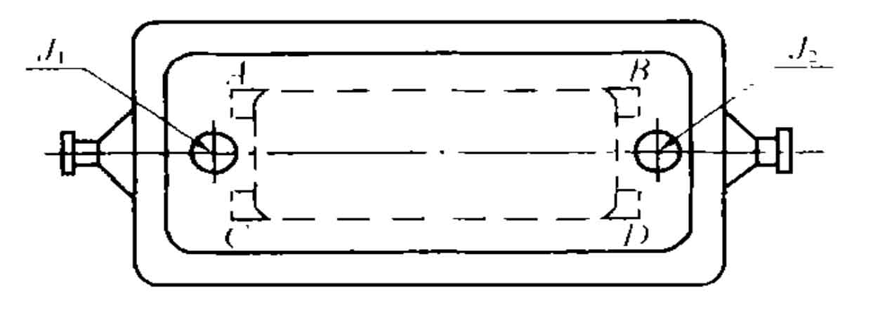
According to the wall thickness, weight and overall dimension of the counterweight iron, 6 feeding risers are determined to be used, of which 4 are blank holder feeding risers, which are respectively located at points a, B, C and D in Figure 3 and connected with the inner sprue. The blank holder section is 20mm × 300mm, so as to keep the riser at a higher temperature during pouring, so as to facilitate feeding.
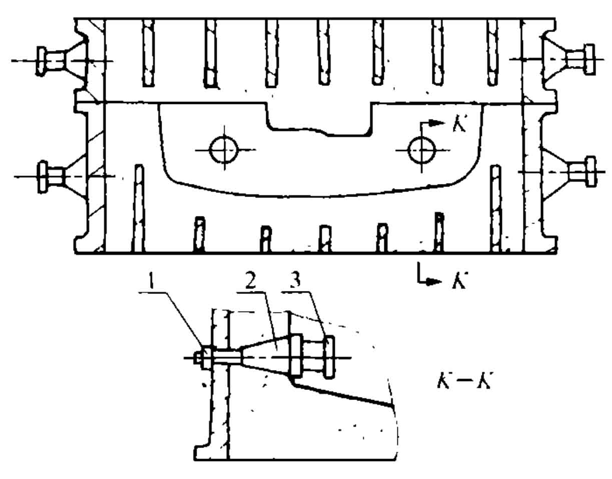
The embedded iron at the screw hole shall be installed in the shape of movable block, that is, the positioning hole shall be made with movable block on the sand mold of the coaxial line of the embedded iron. As shown in Figure 4, the embedded iron 3 is connected with the positioning shaft 2 through threads Insert the positioning shaft into the sand mold positioning hole and fasten it on the lower sand box with nut 1 After casting, unscrew the positioning shaft from the casting for reuse next time.
After the above process method is implemented, the casting of counterweight iron can be realized smoothly, but the following points should be paid attention to: ① sand mold tamping must reach the specified hardness and tamping should be uniform. ② High temperature resistant surface sand and coating shall be used to prevent surface sintering. ③ Low temperature slow baking shall be adopted for sand mold drying to prevent sand mold peeling and cracking. ④ As the counterweight iron is made of low grade gray cast iron, attention should be paid to the expansion stress caused by graphite precipitation during casting solidification. ⑤ The casting shall be thick after pouring for 24h, so as to prevent the casting from cracking.